PRE-RELEASE
DTC P1706 AT VEHICLE SPEED SENSOR CIRCUIT MALFUNCTION (REAR WHEEL)
| DTC P1706 AT VEHICLE SPEED SENSOR CIRCUIT MALFUNCTION (REAR WHEEL) |
DIAGNOSIS:
The input signal circuit of TCM is open or shorted.
TROUBLE SYMPTOM:
No lock-up or excessive tight corner “braking”.
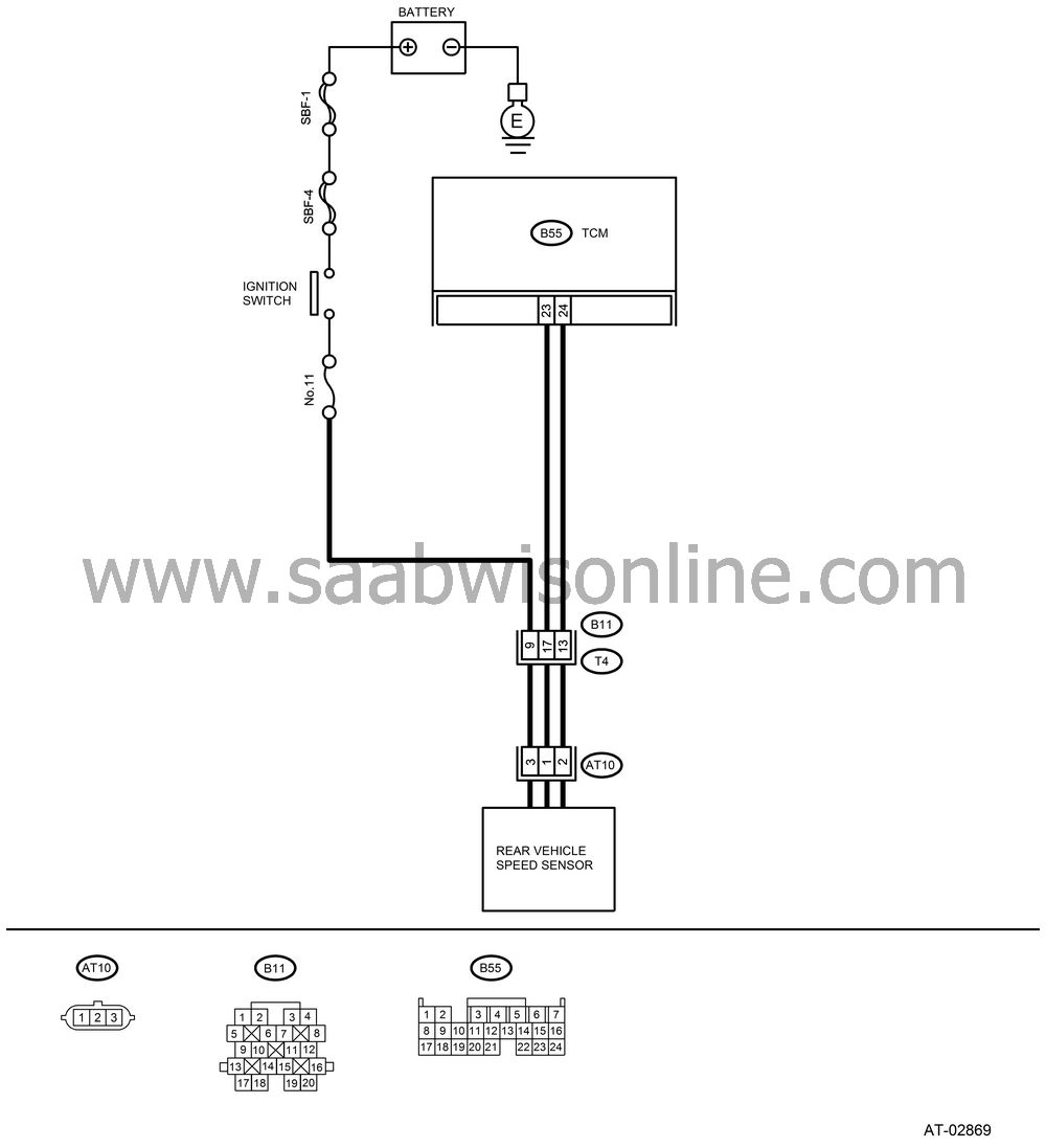
WIRING DIAGRAM:

CHECK IGNITION POWER SUPPLY CIRCUIT.
Turn the ignition switch to OFF.Disconnect the connector from rear vehicle speed sensor.
Turn the ignition switch to ON.
Measure the ignition power supply between rear vehicle speed sensor connector and transmission ground.
Connector & terminal
(AT10) No. 3 (+) — Transmission ground (−):
Is the voltage more than 10 V?
| Yes |
| No |
Check harness between rear vehicle speed sensor and battery for open circuit, short or poor contact. Repair the harness if required.
CHECK HARNESS CONNECTOR BETWEEN TCM AND TRANSMISSION.
Turn the ignition switch to OFF.Measure the resistance of harness between TCM and transmission connector.
Connector & terminal
(B55) No. 23 — (AT10) No. 1:
Is the resistance less than 1 Ω?
| Yes |
| No |
Repair the open circuit or poor contact of connector in harness between TCM and rear vehicle speed sensor connector.
CHECK HARNESS CONNECTOR BETWEEN TCM AND TRANSMISSION.
Measure the resistance of harness between TCM and transmission connector.Connector & terminal
(B54) No. 24 — (AT10) No. 2:
Is the resistance less than 1 Ω?
| Yes |
| No |
Repair the open circuit or poor contact of connector in harness between TCM and rear vehicle speed sensor connector.
CHECK HARNESS CONNECTOR BETWEEN TCM AND TRANSMISSION.
Measure the resistance of harness between TCM and chassis ground.Connector & terminal
(B55) No. 23 — Chassis ground:
Is the resistance more than 1 MΩ?
| Yes |
| No |
Repair the short circuit in harness between TCM and rear vehicle speed sensor connector.
CHECK HARNESS CONNECTOR BETWEEN TCM AND TRANSMISSION.
Measure the resistance of harness between TCM and chassis ground.Connector & terminal
(B55) No. 24 — Chassis ground:
Is the resistance more than 1 MΩ?
| Yes |
| No |
Repair the short circuit in harness between TCM and rear vehicle speed sensor connector.
PREPARE OSCILLOSCOPE.
Do you have an oscilloscope?
| Yes |
| No |
CHECK INPUT SIGNAL FOR TCM.
Connect the connectors to TCM and transmission.Lift-up the vehicle and place rigid racks.
| Note | ||
|
Raise all wheels off ground. |
Start the engine and set vehicle in 20 km/h (12 MPH) condition.
Measure the AC voltage between TCM connector terminals.
Connector & terminal
(B55) No. 24 (+) — No. 23 (−):
Is the voltage more than 2 V?
| Yes |
| No |
Replace the rear vehicle speed sensor.
CHECK INPUT SIGNAL FOR TCM USING OSCILLOSCOPE.
Connect the connectors to TCM and transmission.Lift-up the vehicle and place rigid racks.
| Note | ||
|
Raise all wheels off ground. |
Set the oscilloscope to TCM connector terminals.
Connector & terminal
Positive probe; (B55) No. 24:
Earth lead; (B55) No. 23:
Start the engine and set vehicle in 20 km/h (12 MPH) condition.
Measure the signal voltage indicated on oscilloscope.
Is the pulse voltage approx. 5 V?
| Yes |
| No |
Replace the rear vehicle speed sensor.
CHECK POOR CONTACT.
Is there poor contact in rear vehicle speed sensor circuit?
| Yes |
Repair the poor contact.
| No |


