PRE-RELEASE
OPERATION
| OPERATION |
| READ DIAGNOSTIC TROUBLE CODE (DTC) |
Prepare the Vehicle Diagnostic Interface kit.

Connect the diagnosis cable to Vehicle Diagnostic Interface.
Connect the Vehicle Diagnostic Interface to data link connector.
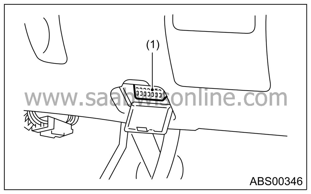
Data link connector located in the lower portion of instrument panel (on the driver’s side).

|
(1)
|
Data link
connector
|
Connect the diagnosis cable to data link connector.
| Important | ||
|
Do not connect the scan tools except for Vehicle Diagnostic Interface and OBD-II general scan tool. |
||
Turn the ignition switch to ON (engine OFF), and start the Vehicle Diagnostic Interface.
On the «Main Menu» display screen, select the {Each System Check}.
On the «System Selection Menu» display screen, select the {Brake Control System}.
Select the {OK} after the information of engine type is displayed.
On the «ABS Diagnosis» display screen, select the {DTC Display}.
On the «DTC Display» display screen, select the {Current DTC} or {History DTC}.
| Display | Contents to be monitored |
|
Current
|
Indicate
the latest DTC on the Vehicle Diagnostic
Interface display.
|
|
Old
|
Indicate
the latest DTC in previous trouble on the Vehicle
Diagnostic Interface display.
|
|
Older
|
Indicate
the latest DTC in second previous trouble on the Vehicle
Diagnostic Interface display.
|
|
Before
3
|
Indicate
the latest DTC in third previous trouble on the Vehicle
Diagnostic Interface display.
|
| READ CURRENT DATA |
On the «Main Menu» display screen, select the {Each System Check}.
On the «System Selection Menu» display screen, select the {Brake Control System}.
Select the {OK} after the information of ABS type is displayed.
On the «Brake Control Diagnosis» display screen, select the {Current Data Display & Save}.
On the «Data Display Menu» display screen, select the {Data Display}.
Using the scroll key, move the display screen up or down until desired data is shown.
| • |
A list
of the support data is shown in the following table.
|
|
| Display screen | Contents to be monitored | Unit of measure |
|
FR Wheel
Speed
|
Wheel
speed detected by Front ABS wheel speed sensor RH is displayed
|
km/h
or MPH
|
|
FL Wheel
Speed
|
Wheel
speed detected by Front ABS wheel speed sensor LH is displayed
|
km/h
or MPH
|
|
RR Wheel
Speed
|
Wheel
speed detected by Rear ABS wheel speed sensor RH is displayed
|
km/h
or MPH
|
|
RL Wheel
Speed
|
Wheel
speed detected by Rear ABS wheel speed sensor LH is displayed
|
km/h
or MPH
|
|
Stop
Light Switch
|
Stop
light switch signal
|
ON
or OFF
|
|
G Sensor
Output Signal
|
Voltage
equivalent to vehicle acceleration detected by analog G sensor is
displayed.
|
m/s
(m/s
2
)
|
|
Valve
Relay Signal
|
Valve
Relay Signal
|
ON
or OFF
|
|
ABS
Warning Lamp
|
ON operation
of ABS warning light is displayed.
|
ON
or OFF
|
|
EBD
Warning Light
|
ON operation
of EBD warning light is displayed.
|
ON
or OFF
|
|
Motor
Relay Monitor
|
Motor
relay monitor voltage is displayed.
|
V
|
|
IG power
supply voltage
|
Voltage
supplied to ABSCM&H/U is displayed.
|
V
|
|
ABS
Control Flag
|
ABS
control condition is displayed.
|
ON
or OFF
|
|
ABS
OK B Signal
|
ABS
system normal/abnormal is displayed.
|
OK
or NG
|
| Note | ||
|
For detailed operation procedure, refer to the “Vehicle Diagnostic Interface OPERATION MANUAL”. |
| CLEAR MEMORY MODE |
On the «Main Menu» display screen, select the {2. Each System Check}.
On the «System Select Menu» display screen, select the {Brake System}.
Select the {OK} after the information of engine type is displayed.
On the «Brake Control Diagnosis» display screen, select the {Clear Memory}.
| Display screen | Contents to be monitored |
|
Clear
memory?
|
Function
of clearing DTC.
|
When the “Done” is shown on display screen, turn the Vehicle Diagnostic Interface and ignition switch to OFF.
| Note | ||
|
For detailed operation procedure, refer to the “Vehicle Diagnostic Interface OPERATION MANUAL”. |
| ABS SEQUENCE CONTROL |
| Display screen | Contents to be monitored | Index No. |
|
ABS sequence control
|
Perform
ABS sequence control by operating valve and pump motor sequentially.
|

|


