PRE-RELEASE
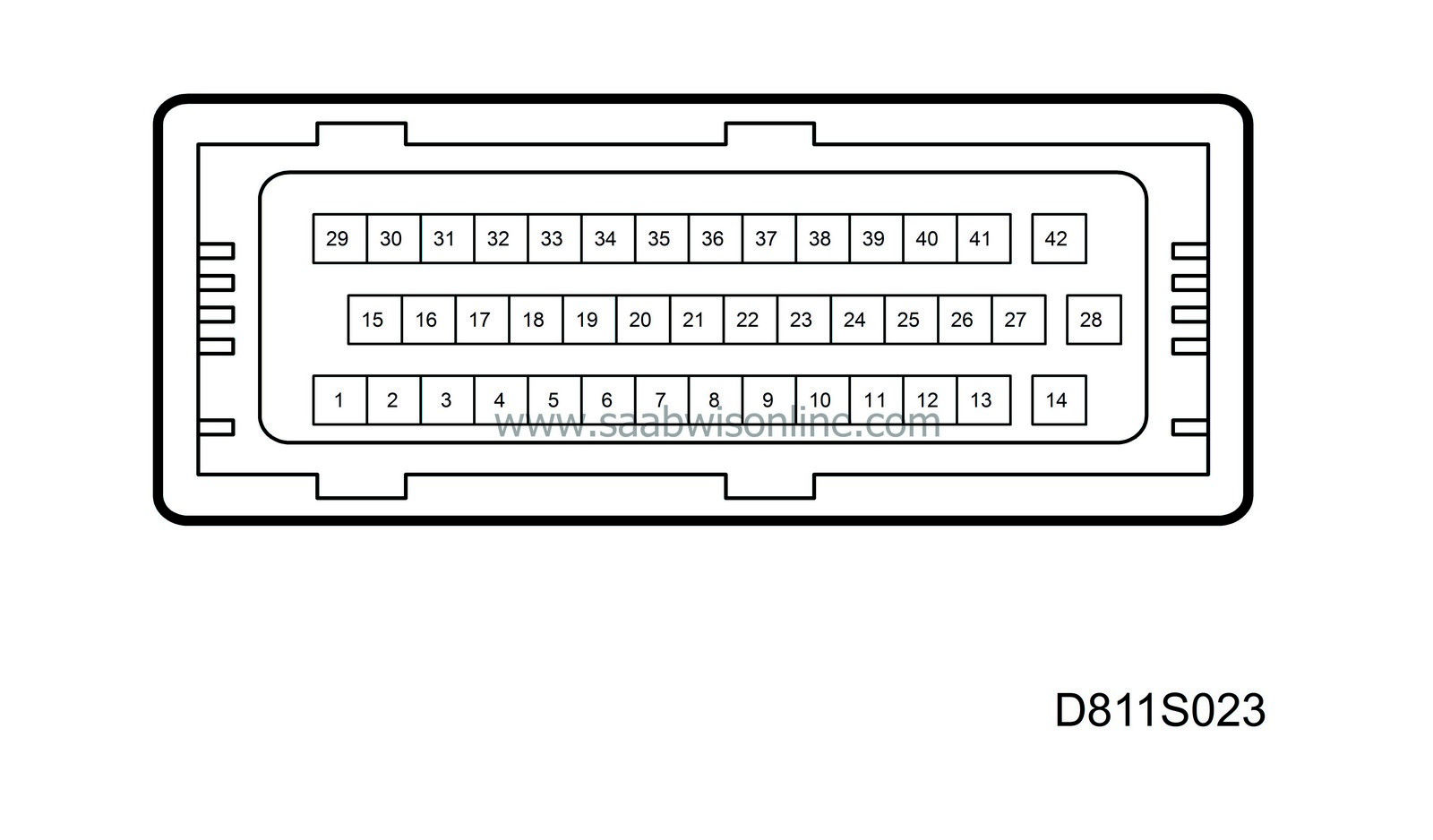
Test readings, control module connections
| Test readings, control module connections |
| Keep in mind |
| • |
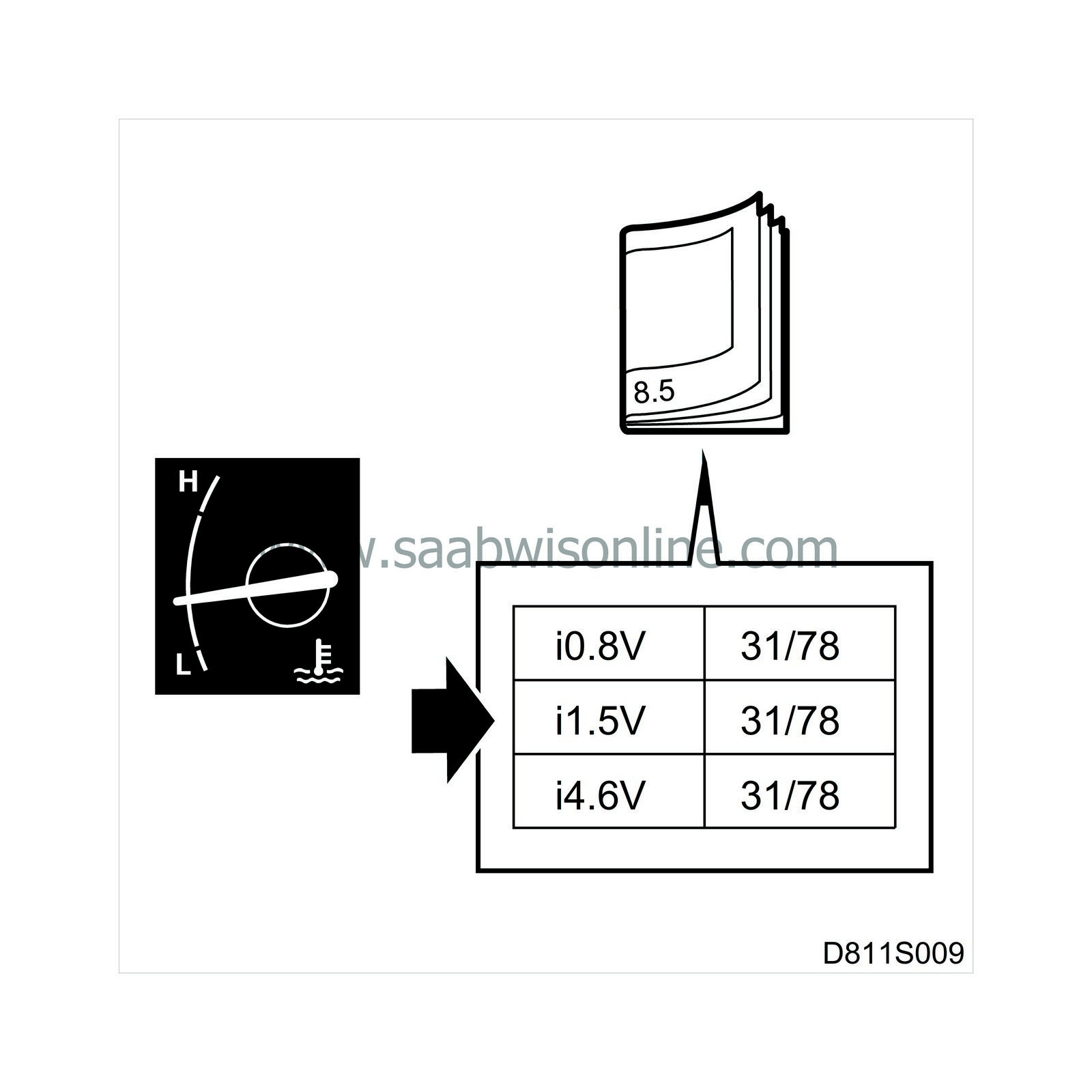
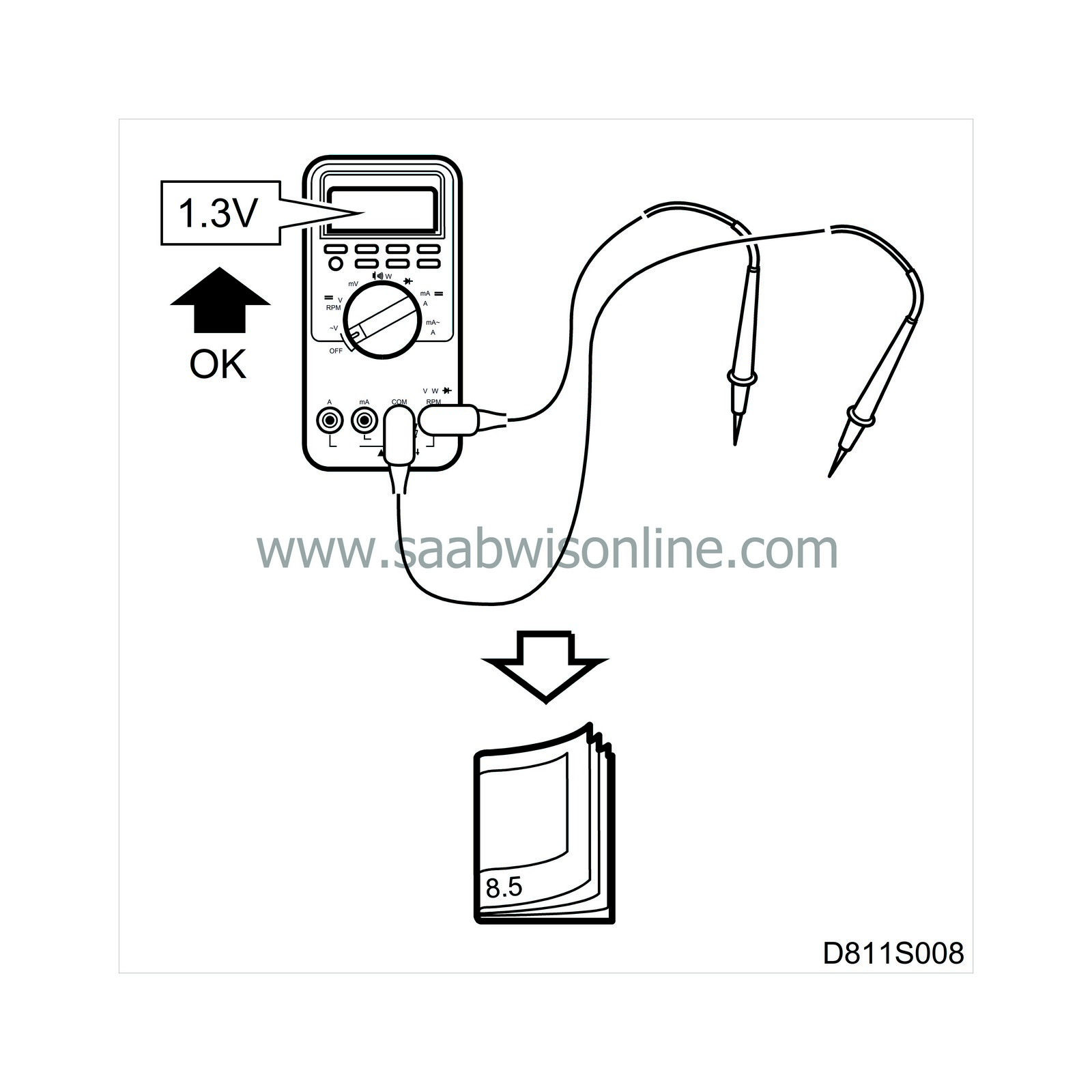
Note the test conditions, and use common sense when assessing the test results.
|
|
| • |
The specified readings are with the ignition in position ON unless otherwise stated.
|
|
| • |
First, check that the control module is supplied with current and is grounded.
|
|
| • |
Then check all sensor inputs and signals from other systems.
|
|
| • |
Finally, check the control module outputs. Remember that the test readings do not indicate whether the actuator is working.
|
|
| • |
If any reading is not correct, consult the wiring diagram to trace the leads, connectors or components that should be checked more thoroughly.

|
|
| • |
The test readings given apply to a calibrated Fluke 88/97.
|
|
| • |
The test readings show the signal's pulse ratio and pulse width. A test instrument with pulse ratio and pulse width measurement must be used. The (+) sign indicates a positive trigger pulse, TRIG+.
|
|

> = greater than; < = less than; ~ = alternating current (LP: LOGIC PROBE P = select pulse; p = visible pulse)
| Pin | Cable colour | Component/function | In/Out | Test conditions | Across | Test reading | |
|
1
|
BN/GY
|
Power supply +54
|
In
|
|
1-29
|
B+
|
|
|
2
|
OG
|
Switch master cylinder upper position
|
In
|
Soft top completely raised
Soft top not completely raised |
2-29
2-29 |
0V
B+ |
|
|
3
|
BU
|
Switch fifth bow cylinder bottom position
|
In
|
Fifth bow in bottom
position Fifth bow not in bottom position |
3-29 3-29 |
0V B+ |
|
|
4
|
BU/WH
|
Microswitch fifth bow intermediate position
|
In
|
Fifth bow in intermediate position
Fifth bow not in intermediate position |
4-29 4-29 |
0V B+ |
|
|
5
|
GY
|
Microswitch, soft top cover latch, LH
|
In
|
Soft top cover locked
Soft top cover unlocked |
5-29
5-29 |
0V
B+ |
|
|
6
|
YE
|
Switch ROOF up position
|
In
|
ROOF button pressed forwards
ROOF button not pressed |
6-29 6-29 |
B+ 0V |
|
|
7
|
YE/BU
|
Switch ALL WINDOWS down
|
In
|
Window switch pressed at rear edge
Window switch not pressed |
7-29 7-29 |
B+ 0V |
|
|
8
|
BU/YE
|
Switch, front right window up
|
In
|
Window switch pressed at front edge
Window switch not pressed |
8-29 8-29 |
B+ 0V |
|
|
9
|
GN/BK
|
Switch, rear left window down
|
In
|
Window switch pressed at rear edge
Window switch not pressed |
9-29 9-29 |
B+ 0V |
|
|
10
|
GN/GY
|
Switch, rear right window down
|
In
|
Window switch pressed at rear edge
Window switch not pressed |
10-29 10-29 |
B+ 0V |
|
|
11
|
|
No connection
|
|
|
|
|
|
|
12
|
|
No connection
|
|
|
|
|
|
|
13
|
GN
|
I-bus+
|
In/Out
|
|
13-29
|
2-3V
|
|
|
14
|
GN/WH
|
VR-bus
|
In/Out
|
|
14-29
|
4.5V
|
|
|
15
|
RD
|
Power supply +30
|
In
|
|
15-29
B+-15 |
B+
0V |
|
|
16
|
GY
|
Switch main cylinder bottom position
|
In
|
Soft top completely lowered
Soft top not completely lowered |
16-29
16-29 |
<0.5V
B+ |
|
|
17
|
GN/BU
|
Microswitch, fifth bow latch, LH
|
In
|
Fifth bow locked
Fifth bow unlocked |
17-29
17-29 |
0V
B+ |
|
|
18
|
VT/WH
|
Switch soft top cover cylinder upper position
|
In
|
Soft top cover completely raised
Soft top cover not completely raised |
18-29 18-29 |
0V B+ |
|
|
19
|
VT/RD
|
Switch windscreen frame latch, RH
|
In
|
Soft top locked to window frame
Soft top not locked to window frame |
19-29 19-29 |
0V B+ |
|
|
20
|
YE/BK
|
ROOF switch down position
|
In
|
ROOF switch pressed backwards
ROOF button not pressed |
20-29 20-29 |
B+ 0V |
|
|
21
|
BK/YE
|
Switch, front left window up
|
In
|
Window switch pressed at front edge
Window switch not pressed |
21-29 21-29 |
B+ 0V |
|
|
22
|
GN/GY
|
Switch, front right window down
|
In
|
Window switch pressed at rear edge
Window switch not pressed |
22-29 22-29 |
B+ 0V |
|
|
23
|
BU/GN
|
Switch, rear right window up
|
In
|
Window switch pressed at front edge
Window switch not pressed |
23-29 23-29 |
B+ 0V |
|
|
24
|
|
No connection
|
|
|
|
|
|
|
25
|
|
No connection
|
|
|
|
|
|
|
26
|
|
No connection
|
|
|
|
|
|
|
27
|
GY/BU
|
Relay, pump motor push
|
Out
|
Activate function with ROOF-switch
Inactive |
27-29 27-29 |
B+ 0V |
|
|
28
|
|
No connection
|
|
|
|
|
|
|
29
|
BK
|
Ground
|
In
|
Control module active |
B+-29
29-B- |
B+
0V |
|
|
30
|
BU/GY
|
Microswitch soft top storage, right and left side connected in series
|
In
|
Soft top storage completely lowered
Soft top storage not completely lowered |
30-29 30-29 |
0V B+ |
|
|
31
|
OG/GN
|
Switch fifth bow cylinder upper position
|
In
|
Fifth bow completely raised
Fifth bow not completely raised |
31-29 31-29 |
0V B+ |
|
|
32
|
BN
|
Microswitch on fifth bow latch, RH
|
In
|
Fifth bow locked
Fifth bow unlocked |
32-29
32-29 |
0V
B+ |
|
|
33
|
BU/YE
|
Microswitch, soft top cover latch, RH
|
In
|
Soft top cover locked
Soft top cover unlocked |
33-29
33-29 |
0V
B+ |
|
|
34
|
VT
|
Switch windscreen frame latch, LH
|
In
|
Soft top locked to window frame
Soft top not locked to window frame |
34-29 34-29 |
0V B+ |
|
|
35
|
YE/RD
|
Switch, ALL WINDOWS up
|
In
|
Window switch pressed at front edge
Window switch not pressed |
35-29 35-29 |
B+ 0V |
|
|
36
|
GY/BU
|
Switch, front left window down
|
In
|
Window switch pressed at rear edge
Window switch not pressed |
36-29 36-29 |
B+ 0V |
|
|
37
|
GN/RD
|
Switch, rear left window up
|
In
|
Window switch pressed at front edge
Window switch not pressed |
37-29 37-29 |
B+ 0V |
|
|
38
|
|
No connection
|
|
|
|
|
|
|
39
|
|
No connection
|
|
|
|
|
|
|
40
|
BN/RD
|
Power supply to switch panel in centre console
|
Out
|
|
40-29
|
B+
|
|
|
41
|
WH
|
I-bus
|
In/Out
|
|
41-29
|
2-3V
|
|
|
42
|
OG/GY
|
Relay, pump motor pull
|
Out
|
Activate function with ROOF-switch
Inactive |
42-29 42-29 |
B+ 0V |
|


