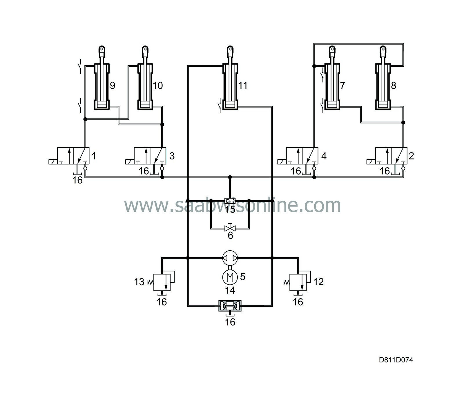
Hydraulic unit, component description
|
|
Hydraulic unit, component description
|
|
1.
|
Hydraulic valve 1 (Fifth bow DOWN)
|
|
2.
|
Hydraulic valve 2 (Main hydraulic cylinder UP)
|
|
3.
|
Hydraulic valve 3 (Fifth bow UP)
|
|
4.
|
Hydraulic valve 4 (Main hydraulic cylinder DOWN)
|
|
6.
|
Emergency operation valve
|
|
7.
|
Main hydraulic cylinder, LH
|
|
8.
|
Main hydraulic cylinder, RH
|
|
9.
|
Fifth bow hydraulic cylinder, LH
|
|
10.
|
Fifth bow hydraulic cylinder, RH
|
|
11.
|
Soft top cover cylinder
|
|
12.
|
Pressure reduction valve (push)
|
|
13.
|
Pressure reduction valve (pull)
|
The pump block forms part of the hydraulic unit and has an integrated fluid reservoir, pump unit with two pressure reduction valves (push/pull), an inlet valve and an electric motor, which drives the pump.
The oil reservoir is bolted to the pump block and only oil part No. (16) 30 32 356 may be used.
The pump unit consists of a 4-cylinder piston pump driven by an electric motor. The motor rotational direction is reversed by the two relays controlled by the STC control module reverse the poles of the power supply. Depending on the rotational direction, the pump can pull and push in both directions and when the soft top cover is to be opened, pressure is created on one side of the hydraulic cylinder that acts on the piston in the pull direction. When the soft top cover is to be closed. the rotational direction of the pump is reversed and pressure is created on the push side of the hydraulic cylinder piston.
The soft top and fifth bow hydraulic cylinder are each controlled by a valve independent of the rotational direction of the pump.
The pressure is reduced to 120+10/-0 bar by the two pressure reduction valves (push and pull) connected after each pressure side, with excess oil being returned to the oil reservoir. The inlet valve opens and delivers oil to the suction side of the pump and closes the connection between the pressure side and the oil reservoir at the same time.
The valve block is connected to the pump block and contains four electromagnetic hydraulic valves, a shuttle valve as well as an emergency operating valve.
The main function of the four valves is to direct the oil flow to the hydraulic cylinders for the main movement as well as the fifth bow hydraulic cylinders. The valve has three connections, oil pressure from the pump, oil pressure to the hydraulic cylinders and return oil to the reservoir. The valve has two positions, “active” and “resting”. When the valve is active, pressure from the pump is connected to pressure to the cylinder and, when the cylinder is resting pressure to the cylinder is connected to return oil to the reservoir. The STC control module controls respective valve by sending messages on the VR-bus. The shuttle valve closes the return oil flow so that pressure can build up at the cylinders for the main movement and fifth bow regardless of the pump rotational direction.
The emergency operating valve is positioned parallel with the shuttle valve. When the emergency operating valve opens, a connection between push and pull sides in the soft top cover hydraulic cylinder is opened. All hydraulic cylinders are double-acting with a connection at each end. The hydraulic cylinders that are positioned on the left side only have one end position switch in the open position, that is, completely contracted piston rod.


