PRE-RELEASE
Dashboard
| Dashboard |
| To remove |
|
|||||||
| 1. |
Disconnect the negative terminal on the battery.

|
|
| 2. |
Pull out the steering column adjustment as far as possible.
|
|
| 3. |
Remove the airbag module by undoing the retaining screws on the back of the steering wheel and unplugging the connector.
|
|
| 4. |
Unplug the horn connector.
|
|
| 5. |
Turn the steering wheel so that the wheels are directed straight forward. Undo the steering shaft nut, but not completely.
|
|
| 6. |
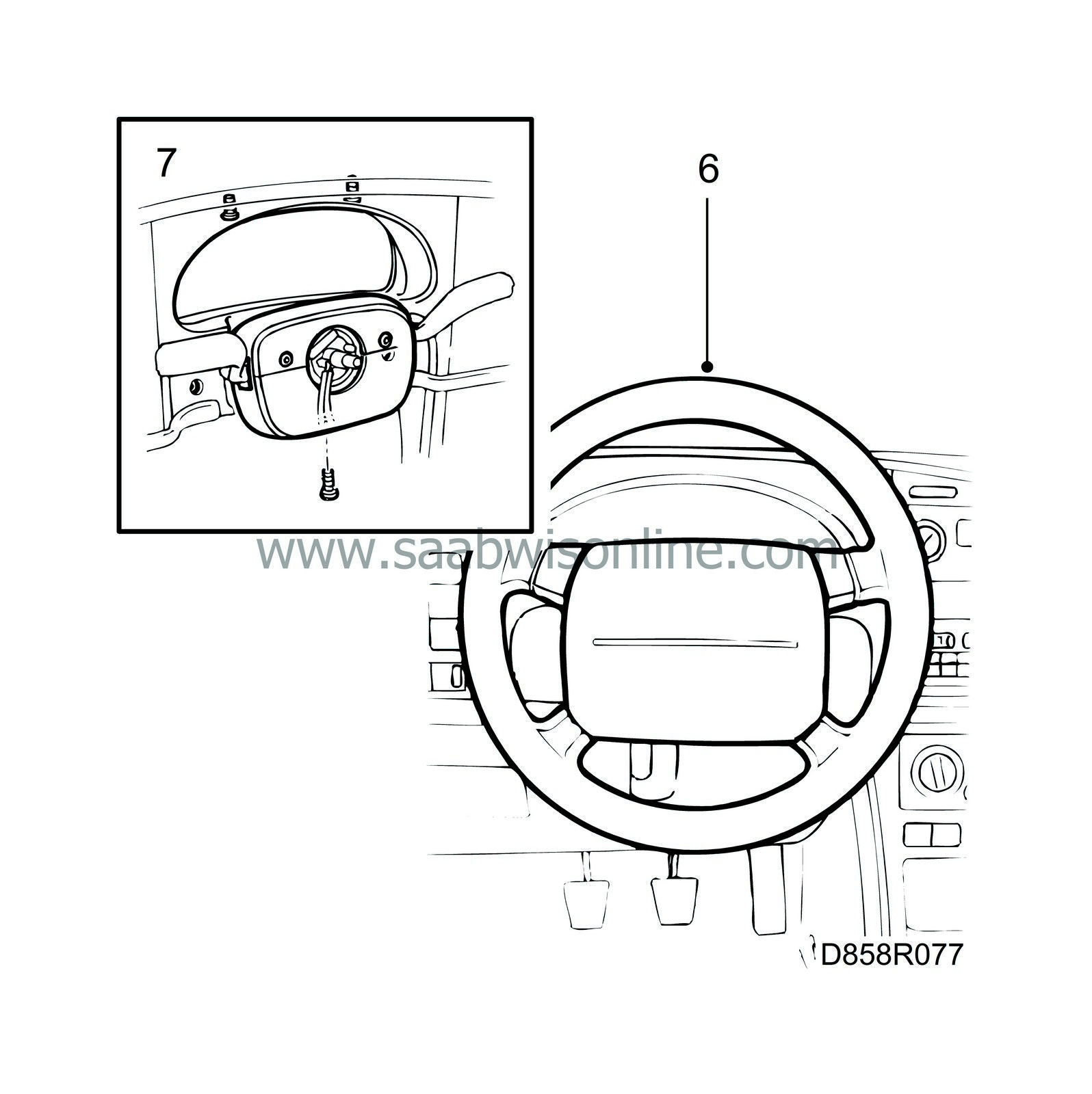
Loosen the steering wheel by rocking it from side to side, remove the connectors and unscrew the steering shaft nut.
|
|
| 7. |
Remove the top and bottom cover of the steering column joint by unscrewing the retaining screws.
|
|
| 8. |
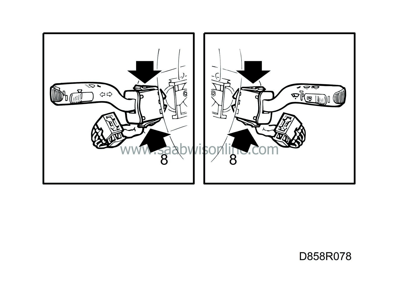
Remove the steering column controls by pressing in the two clips on each mounting and pulling straight out. Unplug the connectors.
|
|
| 9. |
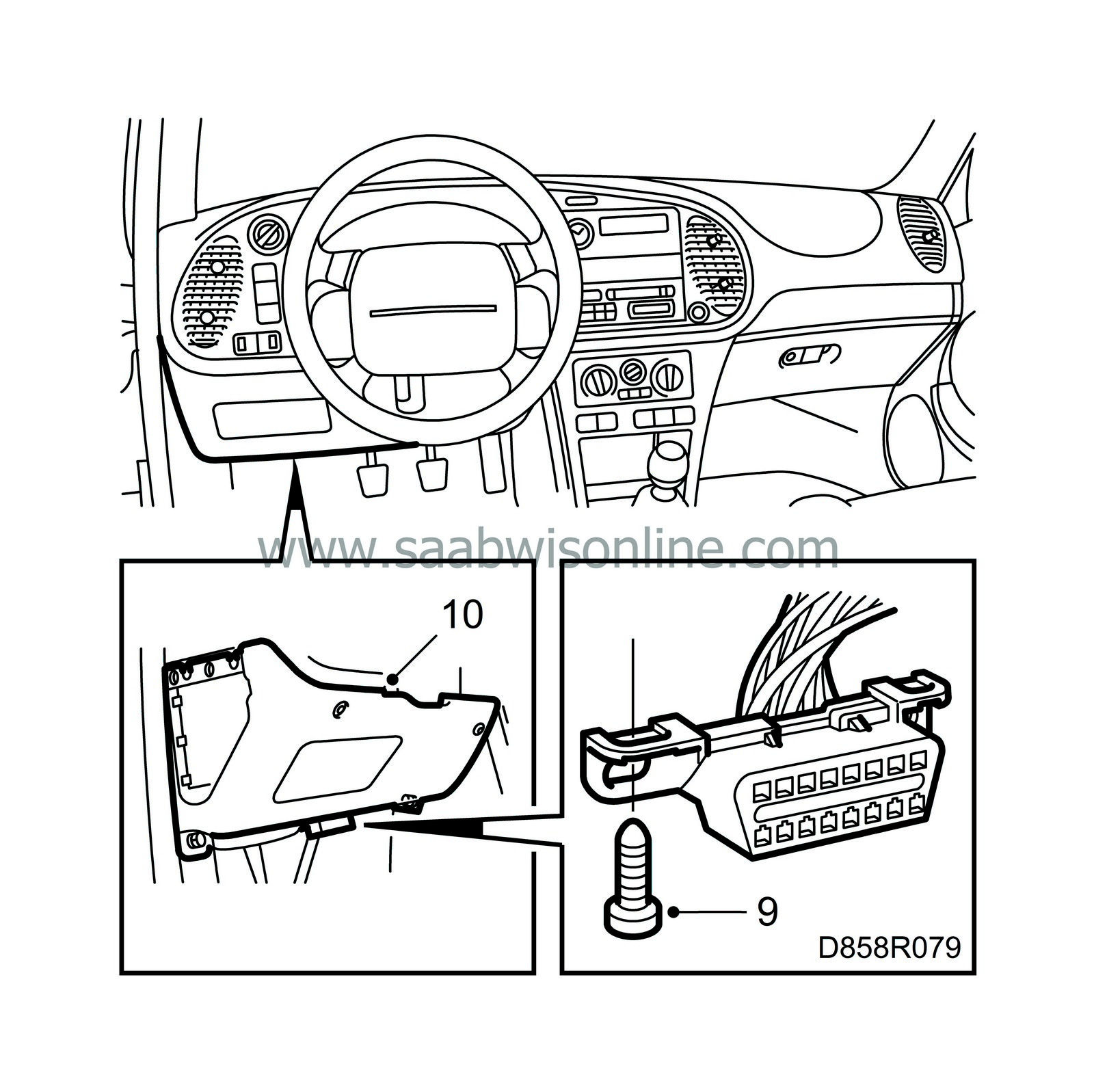
Remove the data link connector. It is located in the lower dashboard panel on the driver's side.
|
|
| 10. |
Undo the lower panel retaining screws and the expansion rivets at the front. The expansion rivets are removed by first pushing the centre further into the rivet.
|
|
| 11. |
Remove the radio unit by inserting the "forks" and pulling it out. Unplug the antenna and the connectors.

|
|
| 12. |
Undo the storage compartment if fitted.
|
|
| 13. |
Detach the radio insert cartridge with a screwdriver.
|
|
| 14. |
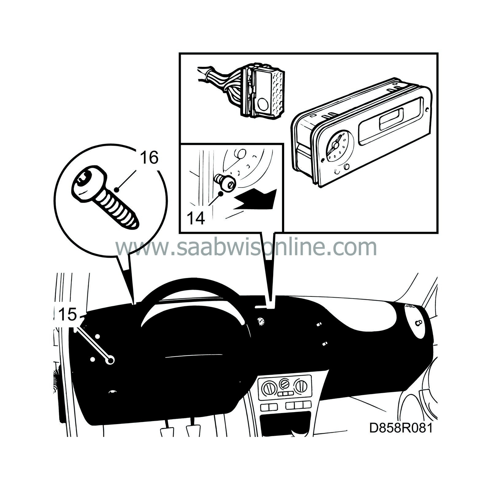
Remove the SID unit using draw-in bolts (M3) and unplug the connector.
|
|
| 15. |
Remove the light switch and the switch for the headlamp beam adjustment by pressing them out from the rear.
|
|
| 16. |
Unscrew the instrument plate retaining screws.
|
|
| 17. |
Detach the top of the instrument plate. Make sure the snap fasteners on the sides are free. Lift out the plate.
|
|
| 18. |
Unplug all the connectors on the instrument plate.
|
|
| 19. |
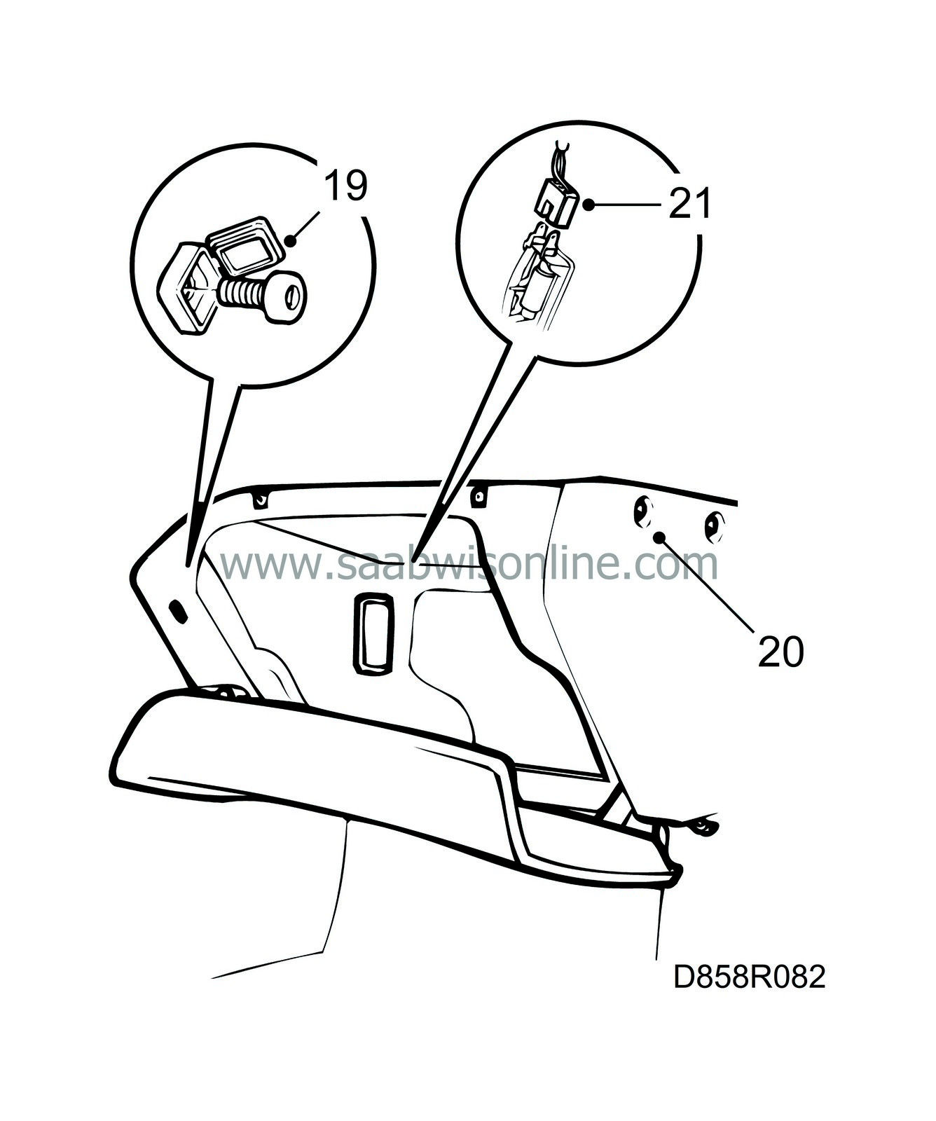
Open the glove box. Open the cover and unscrew the retaining screws.
|
|
| 20. |
Remove the remaining retaining screws and mounting bolts as well as the expansion rivet at the front and release the snap fasteners from the bulkhead bracket.
|
|
| 21. |
Pull out the glove box and unplug the connector for the glove box illumination.
|
|
| 22. |
Lift out the glove box.
|
|
| 23. |
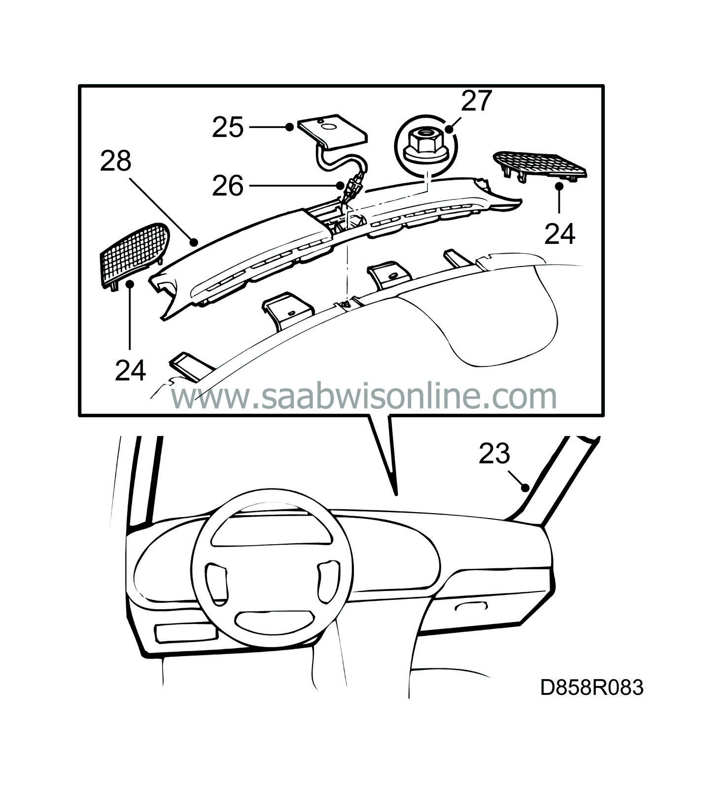
Pull of the rubber strips from the A-pillars and remove the pillar trim (fastened with clips).
|
|
| 24. |
Undo the left and right-hand loudspeaker grilles with a screwdriver.
|
|
| 25. |
Remove the cover on the solar sensor by pulling it slightly backwards and lifting it.
|
|
| 26. |
Cars with ACC and/or alarm:
Unplug the connector for the solar sensor and/or alarm.
|
|
| 27. |
Remove the retaining nuts on the defroster cover and dashboard.
|
|
| 28. |
Remove the defroster cover by lifting it straight up at the rear (fastened with clips). Move it sideways to clear the tabs on the dashboard and lift it off.
|
|
| 29. |
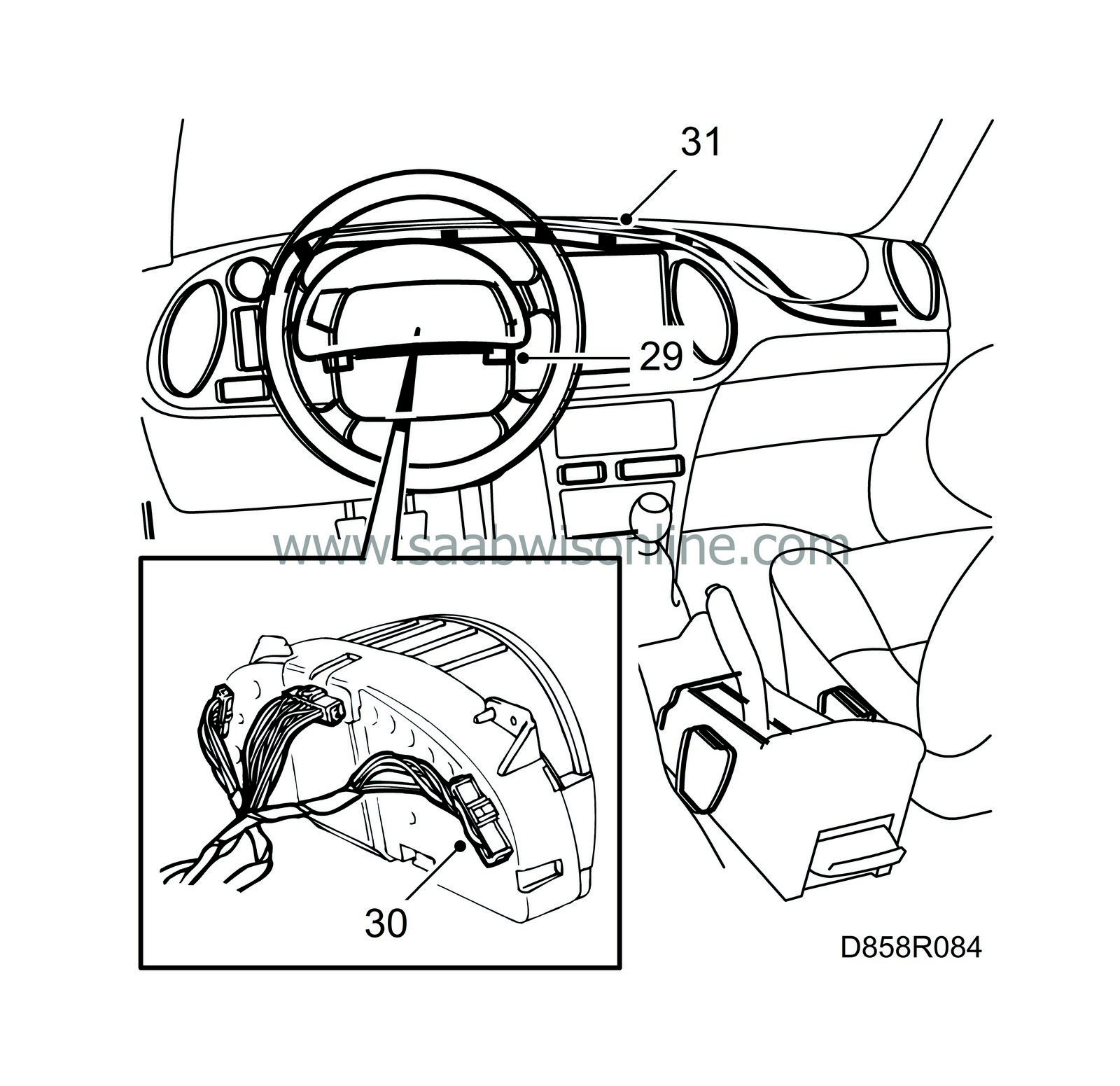
Undo the main instrument unit retaining screws and pull the instrument straight out.
|
|
| 30. |
Unplug the connector.
|
|
| 31. |
Release the wiring loom under the dashboard by cutting the cable tie.
The tie on the passenger side can be opened.
|
|
| 32. |
Remove the floor air duct on the driver's side.

|
|
| 33. |
Undo the fuse board by undoing the two retaining screws and let it hang.
|
|
| 34. |
Undo the dashboard retaining bolts on the A-pillars.
|
|
| 35. |
Press out the heat control panel and undo the expansion rivets securing the dashboard to the centre console (press in the centre pin about 3 mm and pull out the rivet).
|
|
| 36. |
Cars with airbag on the passenger side:
Unplug the connector and remove the nut securing the brace.

|
|
| 37. |
Undo the air ducts to the right-hand and centre air vents.
|
|
| 38. |
Undo the cable ties securing the loudspeaker connection on the right-hand side and unplug the loudspeaker connector.
|
|
| 39. |
Undo the retaining bolts situated on each side of the loudspeakers.
|
|
| 40. |
Lift off the dashboard carefully.
|
|
| To fit |
| 1. |
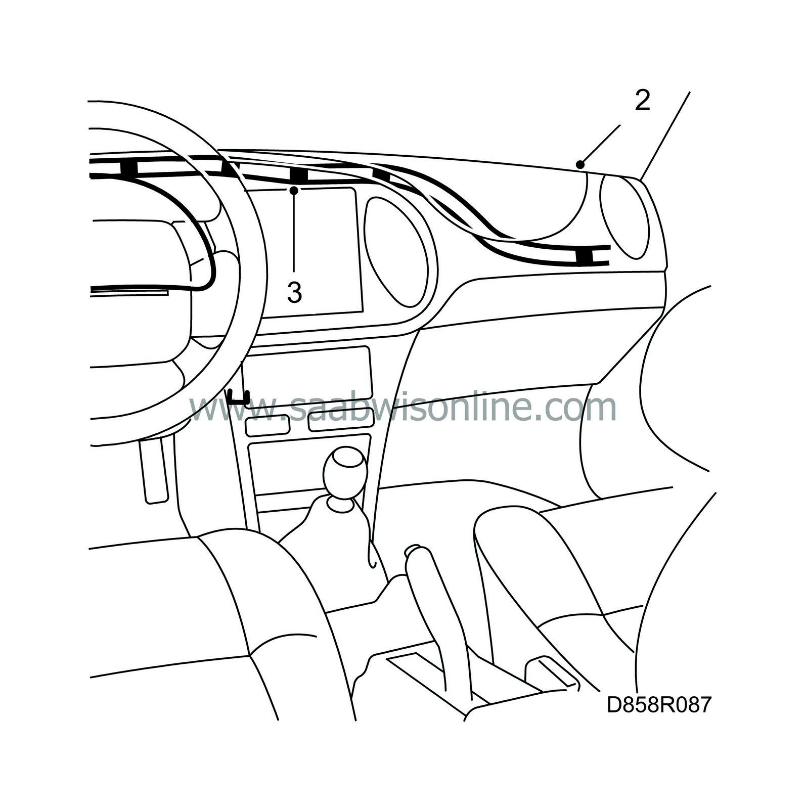
Replace damaged cable ties.
|
|
| 2. |
Lift the entire dashboard roughly into position. It must still be accessible to carry out work underneath it. Lay all the connectors in their respective locations.
|
|
| 3. |
Fit the wiring loom under the dashboard.
|
|
| 4. |
Connect the air duct for the centre air vent to the heating and ventilation unit.
|
|
| 5. |
Plug in the connectors for the left and right-hand loudspeakers.
|
|
| 6. |
Position the dashboard correctly. Be careful not to pinch the wiring.
Cars with airbag on the passenger side:
Make sure the bolt securing the brace is correctly positioned.
|
|
| 7. |
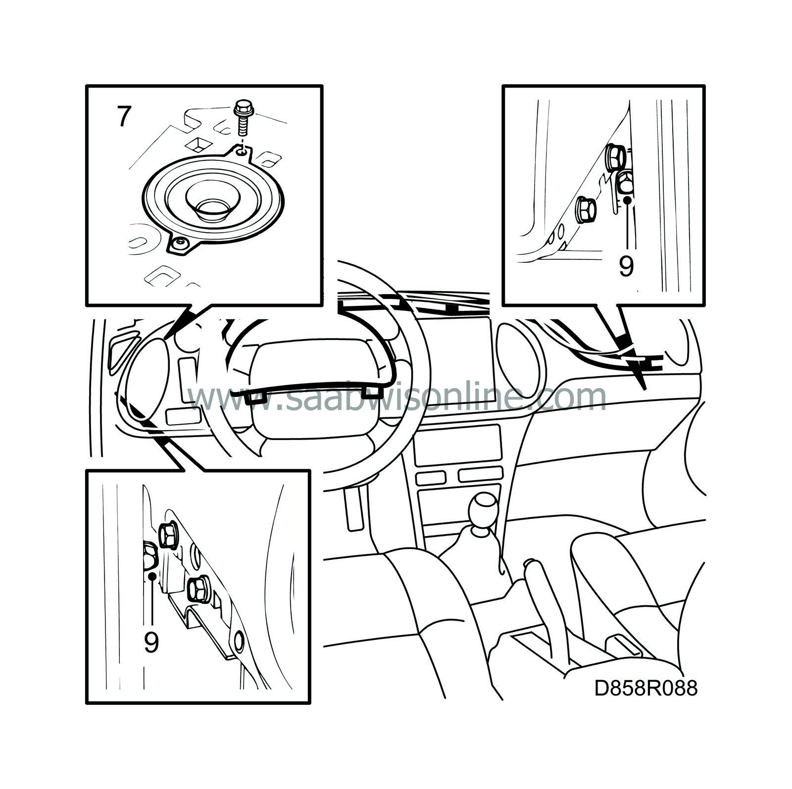
Fit the dashboard bolts at the side of each loudspeaker.
|
|
| 8. |
Connect the right-hand air vent duct.
|
|
| 9. |
Fit the dashboard retaining bolts to their respective A-pillar.
|
|
| 10. |
Cars with airbag on the passenger side:
Fit the nut securing the airbag brace and plug in the connector.

Tightening torque: 20 Nm (15 lbf ft) |
|
| 11. |
Fasten the dashboard to the centre console with the expansion rivets.
|
|
| 12. |
Fit the heater control panel and associated components.
|
|
| 13. |
Fit the fuse board.
|
|
| 14. |
Plug in the main instrument unit connector and fit the instrument.
|
|
| 15. |
Place the defroster cover so that it is possible to move it to one side and hook onto the tabs on the dashboard. Press on the cover (clips).

|
|
| 16. |
Screw on the retaining nut securing both the cover and the dashboard in the space for the solar sensor.
|
|
| 17. |
Cars with ACC and/or alarm:
Plug in the connectors for the solar sensor and/or the alarm and put the solar sensor in place.
|
|
| 18. |
Fit the cover on the solar sensor.
|
|
| 19. |
Press on the left and right-hand loudspeaker grilles. The grilles are fastened with clips.
|
|
| 20. |
Fit the left and right-hand A-pillar trims (clips). Press on the rubber A-pillar strips. Make sure they are overlapping the pillar trim.
|
|
| 21. |
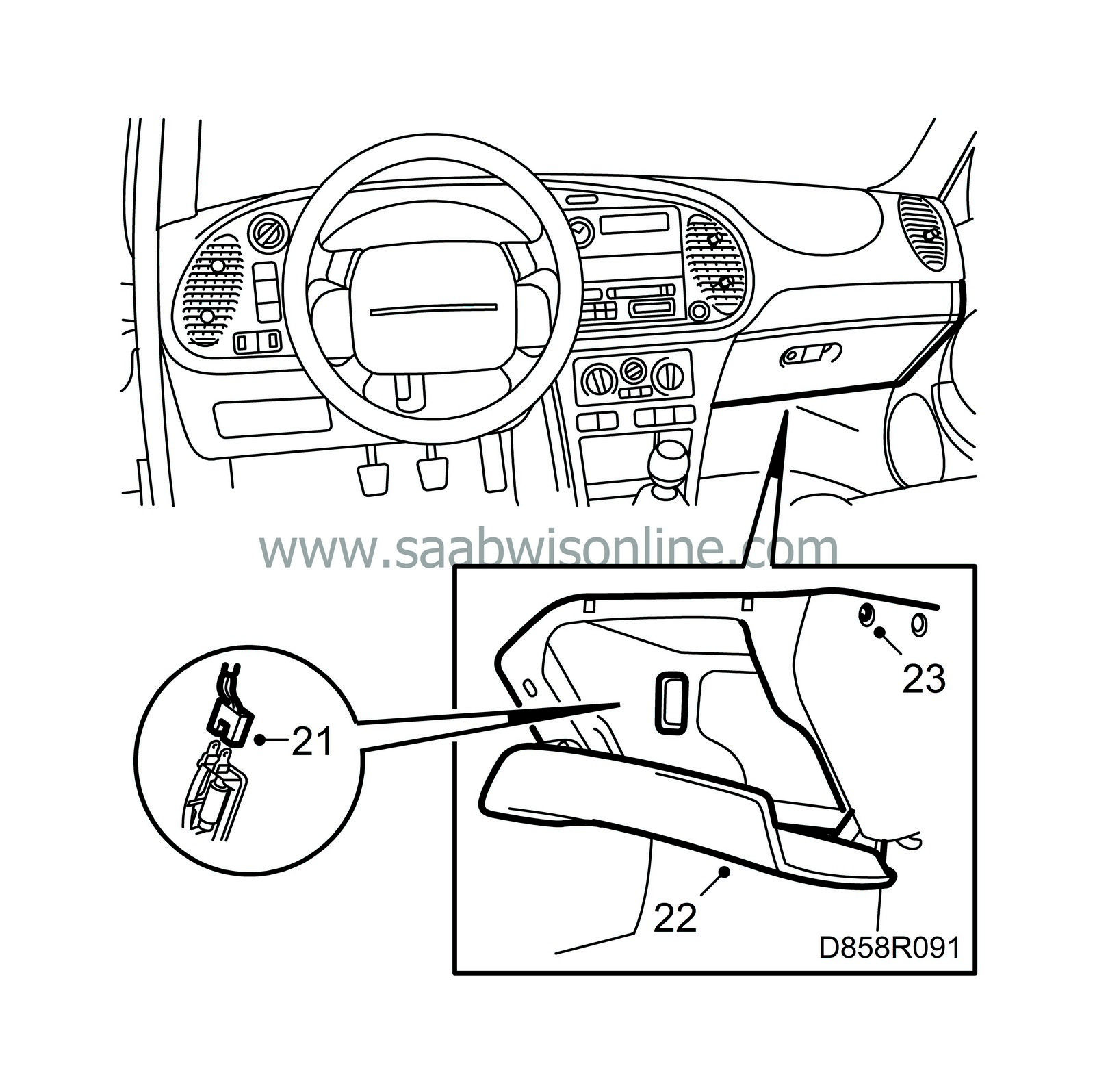
Plug in the connector for the glove box illumination.
|
|
| 22. |
Put the glove box in place.
|
|
| 23. |
Fit the glove box retaining screws and the expansion rivet.
|
|
| 24. |
Put the instrument plate roughly in place.

|
|
| 25. |
Plug in the following connectors: Left of steering wheel (top to bottom) Rear fog lights, black connector Front fog lights, green connector Dummy button Headlamp beam adjuster, orange connector Instrument lighting, white connector, and right of steering wheel: Hazard flashers and Seat-belt lamp
|
|||||||
| 26. |
Fit the instrument plate by first inserting the bottom edge and then pressing on the top edge.
|
|
| 27. |
Fit the instrument plate retaining screws.
|
|
| 28. |
Press in all the switches on the left-hand side of the steering wheel.
|
|
| 29. |
Fit the SID unit.
|
|
| 30. |
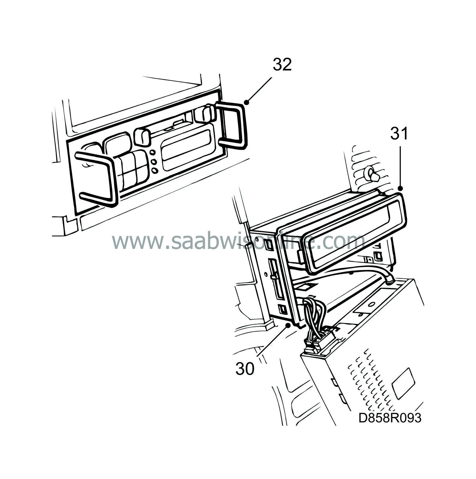
Fit the radio insert cartridge.
|
|
| 31. |
Fit the storage compartment where applicable.
|
|
| 32. |
Plug in the radio connectors and the antenna. Fit the radio into the insert cartridge.
|
|
| 33. |
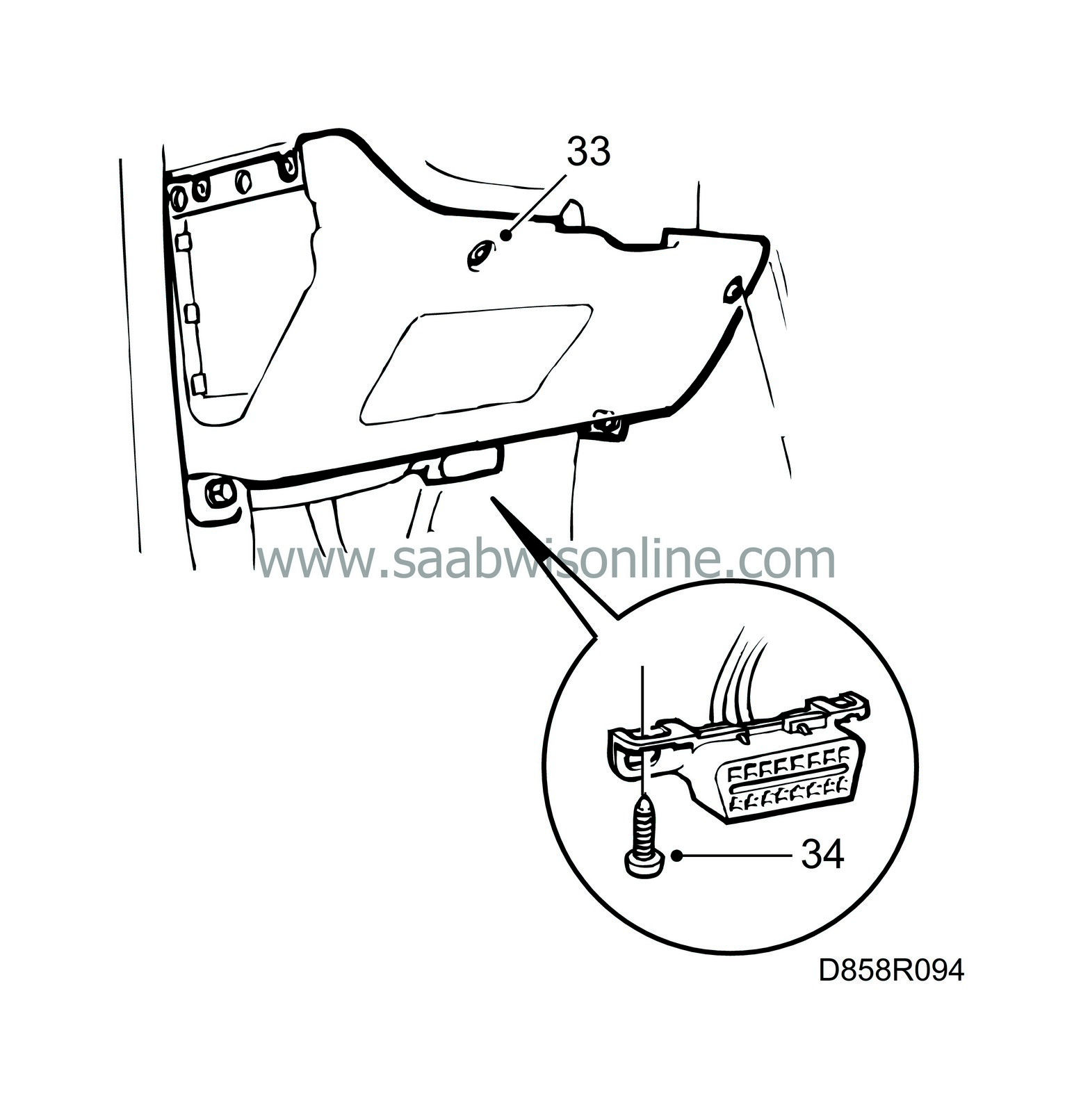
Fit the lower panel on the driver's side.
|
|
| 34. |
Fit the data link connector.
|
|
| 35. |
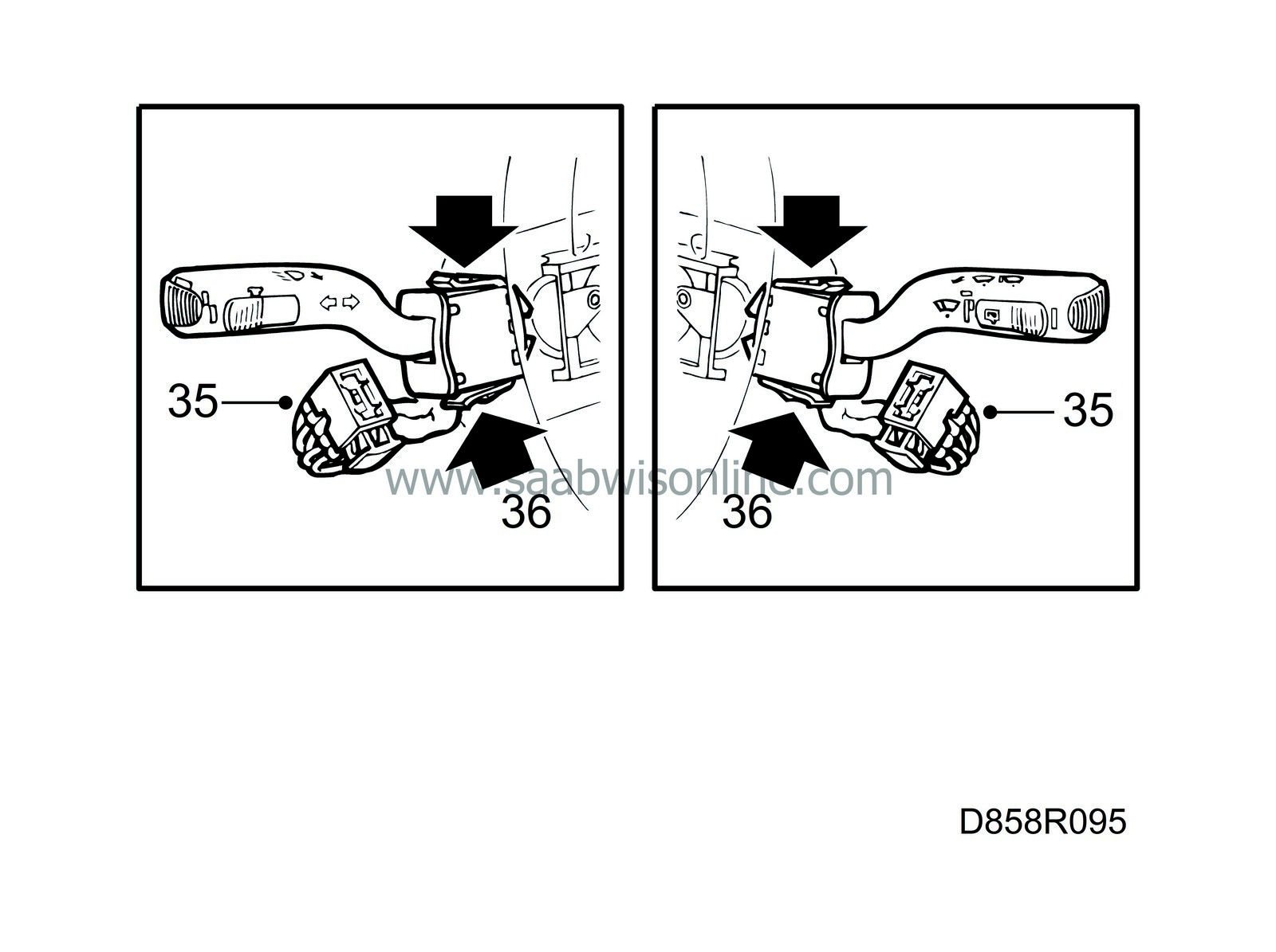
Plug in the connectors to the steering column controls. The wiper control (black mounting) to the right. Direction indicators (white mounting) to the left.
|
|
| 36. |
Fit the steering column controls.
|
|||||||||
| 37. |
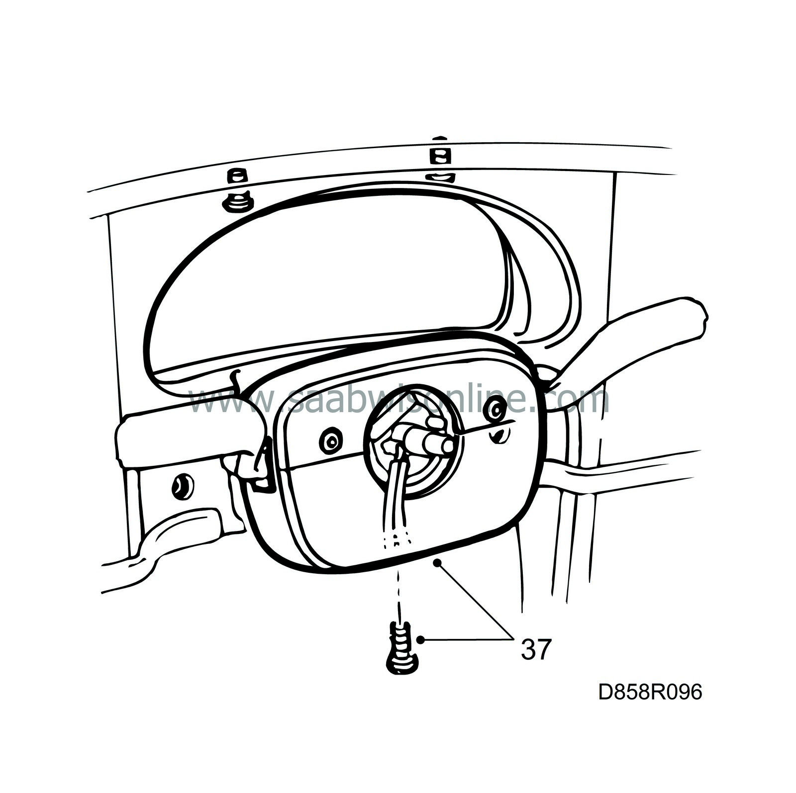
Fit the top and bottom cover of the steering column joint.
|
|
| 38. |
Turn the contact roller anti-clockwise to its end position and then back 2 turns.
|
|
| 39. |
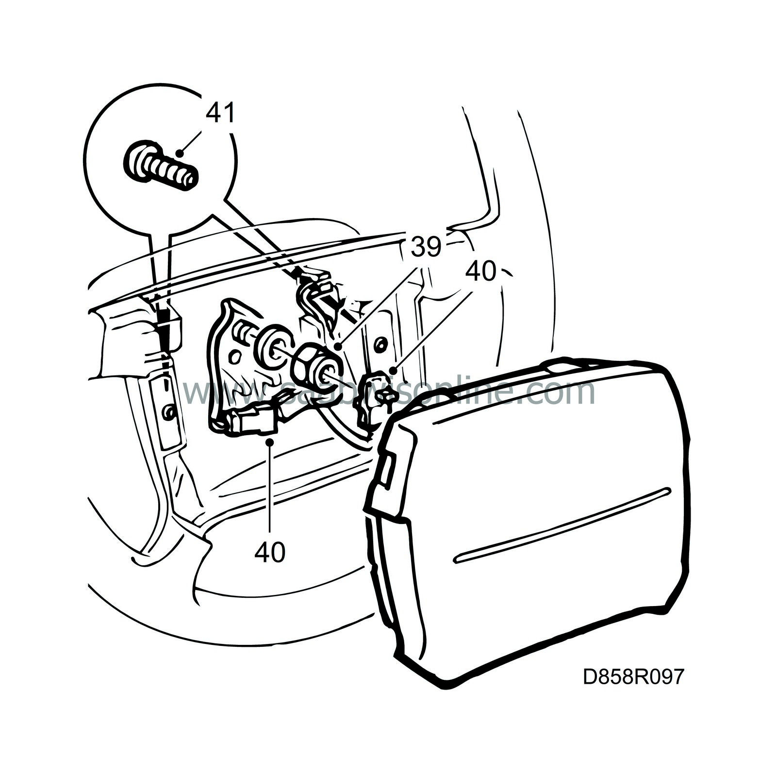
Insert the connectors for the airbag module and the horn through the steering wheel and fit the steering wheel.
|
|
| 40. |
Plug in the connectors for the horn and the airbag module.
|
|
| 41. |
Tighten the airbag module retaining screws.
|
|
| 42. |
Connect the negative battery terminal.
|
|
| 43. |
Connect the diagnostics tool and erase any diagnostic trouble code.
|
|

 Warning

