(854-2383) Difficult to operate temperature and air distribution control knobs
|
SERVICE INFORMATION
|
|
Bulletin Nbr:
|
854-2383
|
|
Date:
...........
|
November 2002
|
|
Market:
|
all
|
|
|
Difficult to operate temperature and air distribution control knobs
|
This SI replaces SI 854-2205 and SI 870-2270
For cars with MCC only
For cars with MCC only 9-3 M98-M00 up to and incl. VIN Y2016481 and Y7005479.
The heat and air distribution control knobs can be difficult to move. The reason for this is twofold: grease missing from certain locations in the heating and ventilation unit and the drum which is pressed against the unit.
Perform the following procedures after customer complaint
Symptom description
Difficult to operate temperature and air distribution control knobs. Difficult to control air flow and adjust temperature.
87 81 718 (CA: 30576981) Silicone grease (enough for approx. 2 cars)
79 76 897 (CA: 30509261) Screw, 2 per car
If necessary :
51 74 669 (CA: 30585921) Cable
53 35 906 (CA: 30591714) Shaft kit, air distribution
53 30 923 (CA: 30587279) Shaft kit, temperature control knob
53 31 665 (CA: 30586362) Control knob
43 64 279 (CA: 30550626) Telescoping control shaft between control panel and heating and ventilation unit
92 88 127 (CA: 30522088) Butyl tape (enough for approx. 20 cars)
|
1.
|
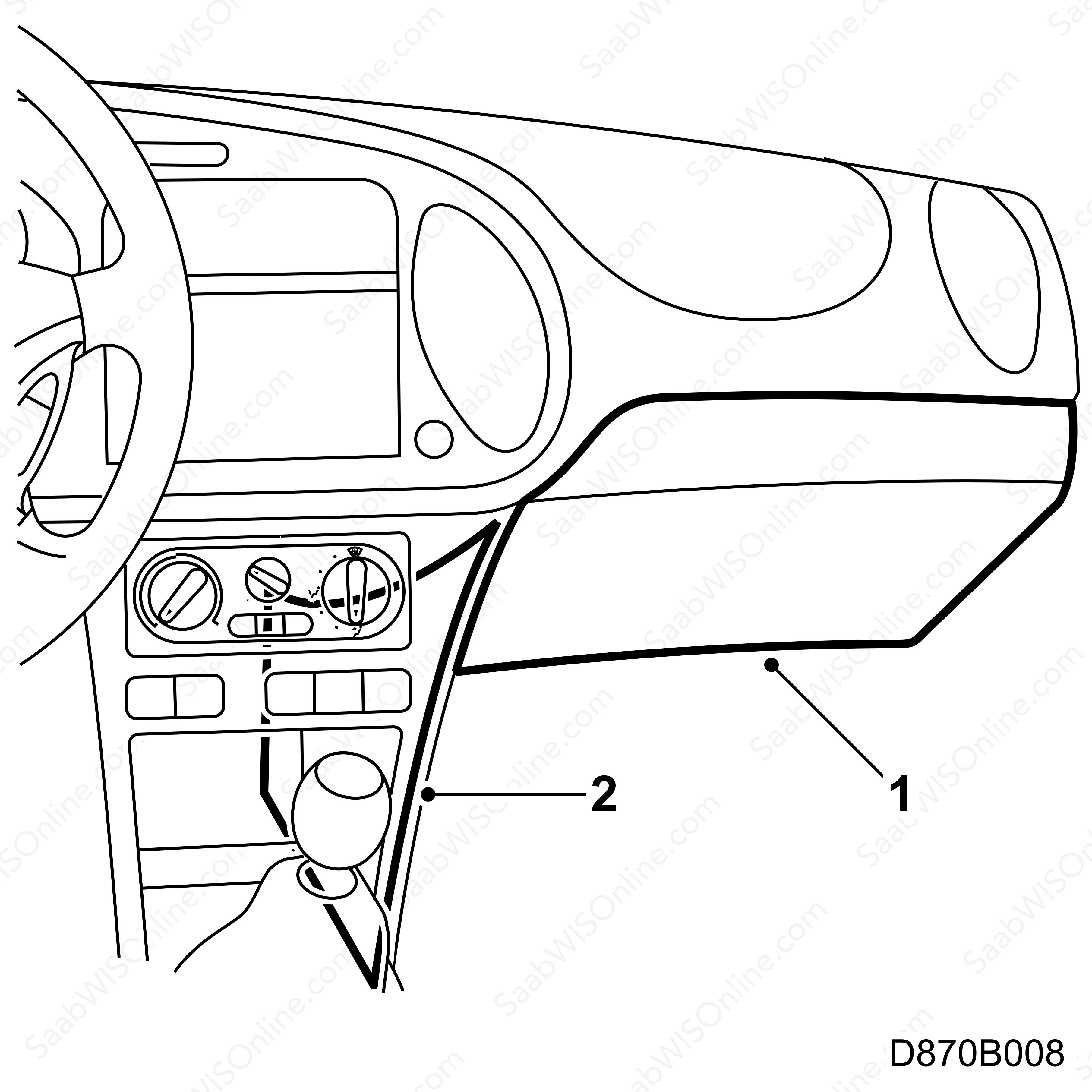
Remove the glove box.
|
|
2.
|
Remove the centre console side panel.
|
|
3.
|
If necessary, remove the knee shield stay.
|
|
4.
|
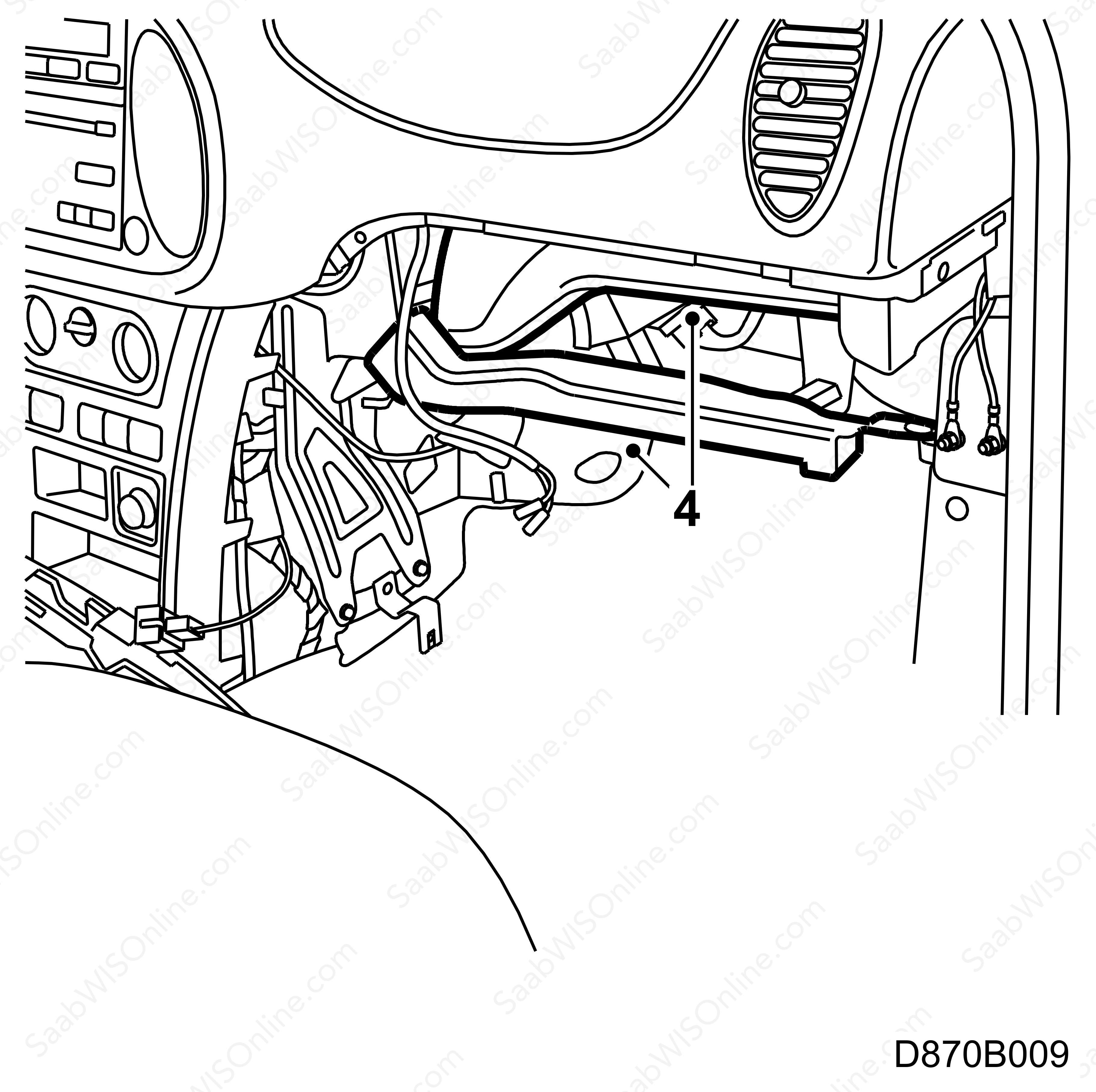
Remove the air ducts.
|
|
5.
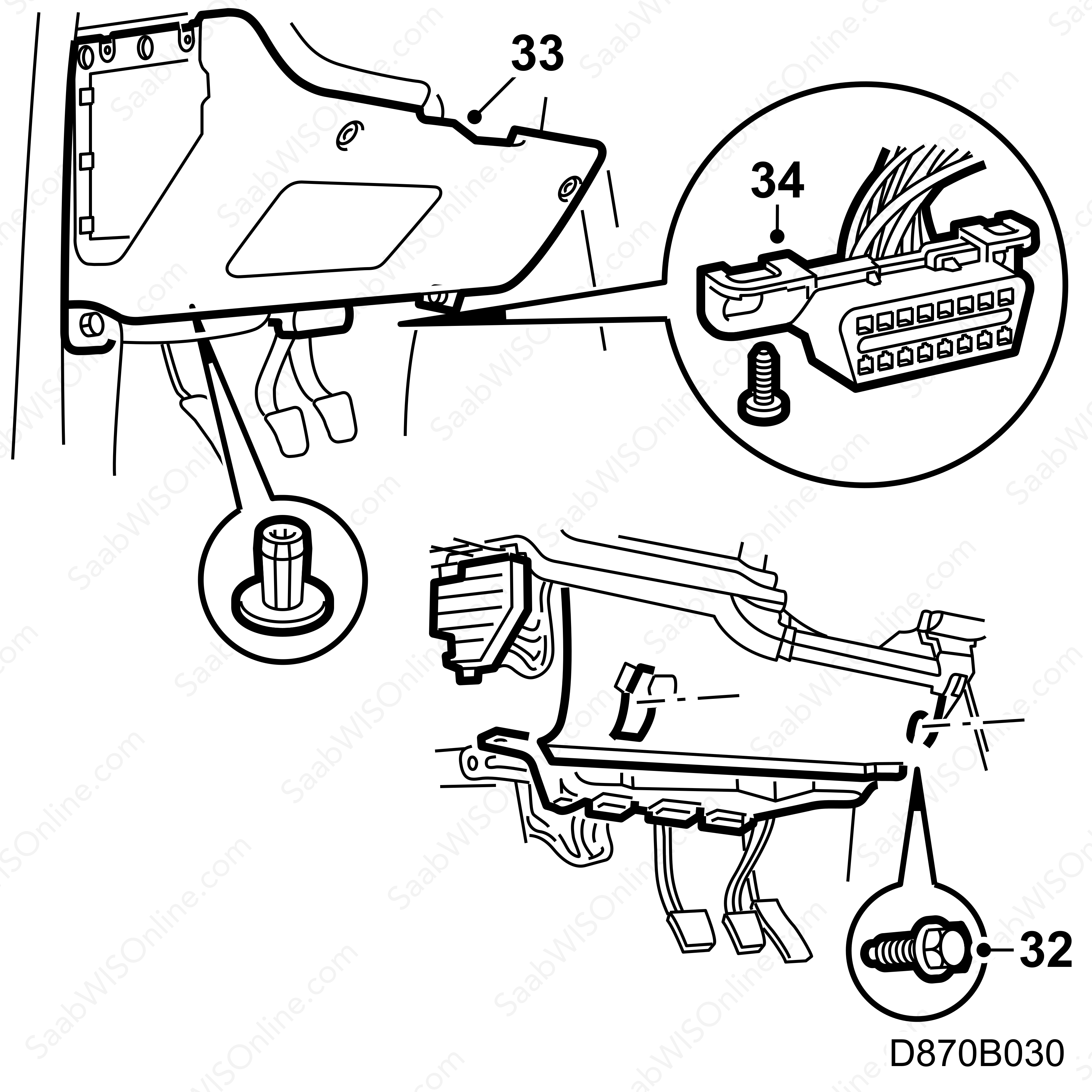
|
Remove the data link connector and the lower dashboard section on the driver's side.

|
|
6.
|
Remove the knee shield on the driver's side.
|
|
7.
|
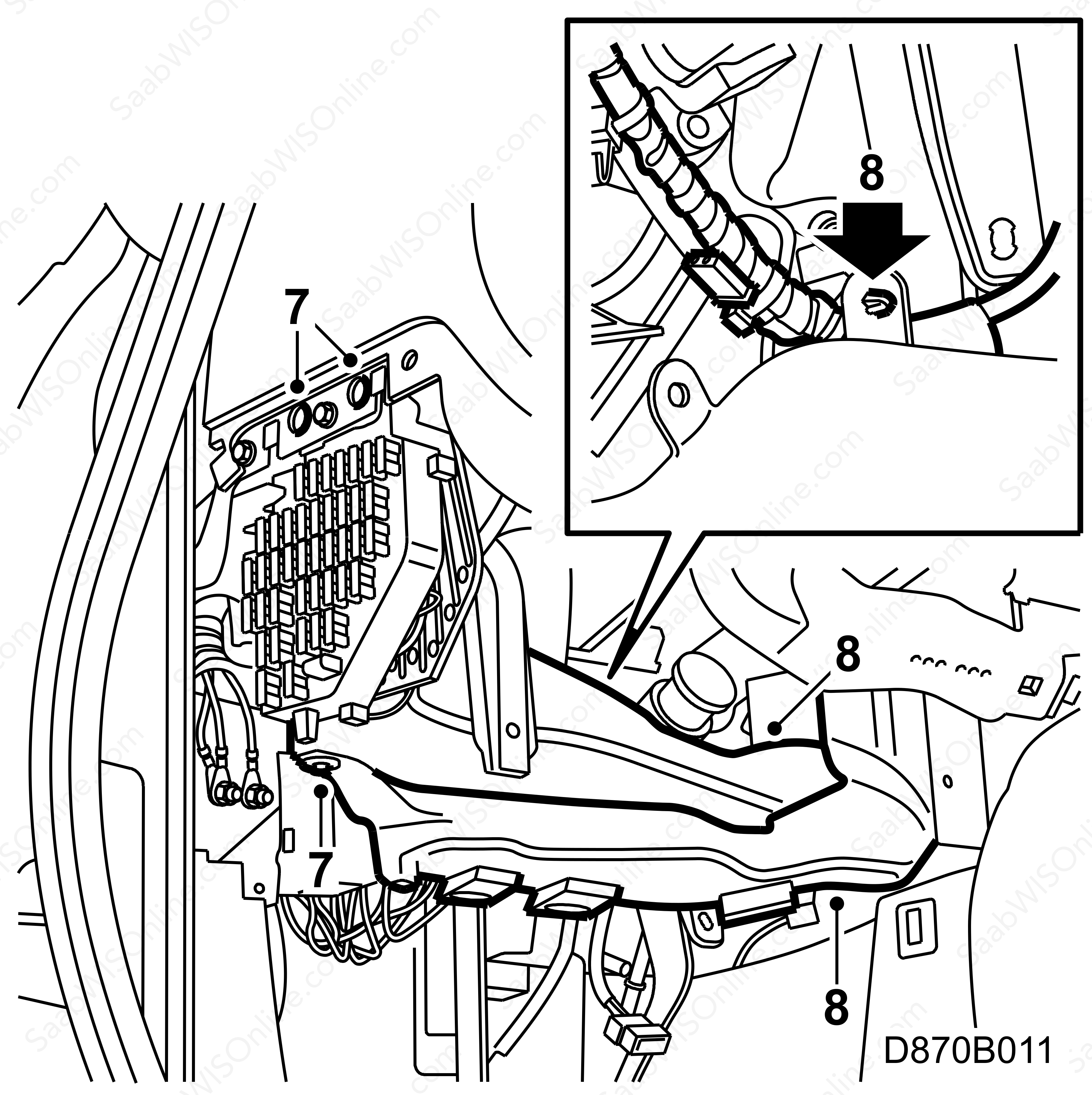
Loosen the screws and move the fuse board aside.
|
|
|
9.a.
|
that the temperature control knob is not damaged or difficult to move and that the temperature control cable is not difficult to move. Replace the temperature control knob if necessary, see the following method description for "Replacing temperature control knob and shaft". Check the temperature control cable by disconnecting the cable from the lever and turning the temperature controls. If the knob is difficult to manoeuvre, replace if necessary, see WIS - 9-3 - Body - MCC - Adjustment/Replacement - Control cable. Fit the cable to the lever.
|
|
|
9.b.
|
that the air distribution control knob functions satisfactorily. Replace if necessary, see the following method description "Replacing the air distribution control knob shaft".
|
|
|
9.c.
|
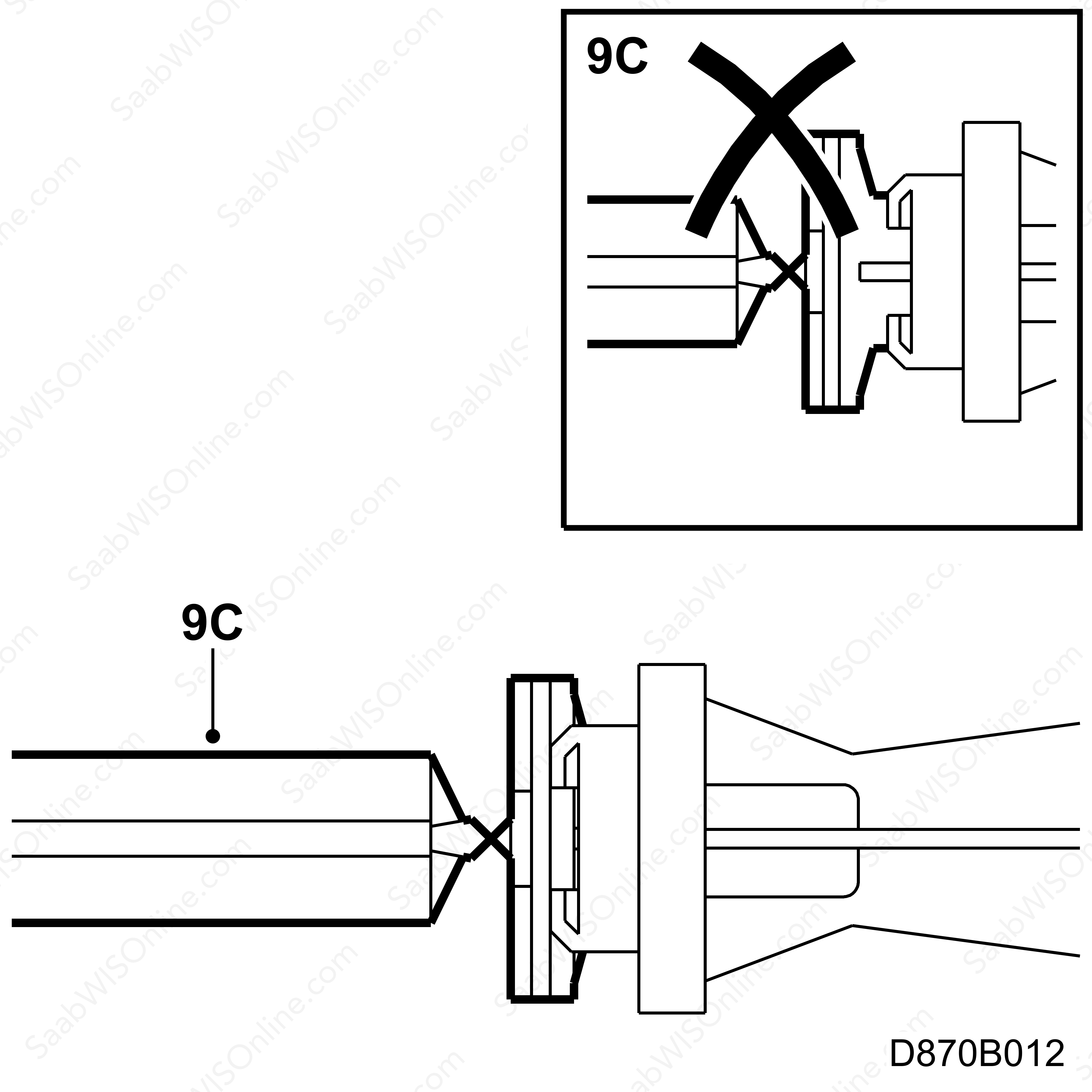
that there is no play with regards to the telescoping air distribution control shaft in relation to the knob and that it is properly pressed into the heating and ventilation unit. Replace if necessary, see WIS - 9-3 - Body - MCC - Adjustment/Replacement - Control shaft.
|
|
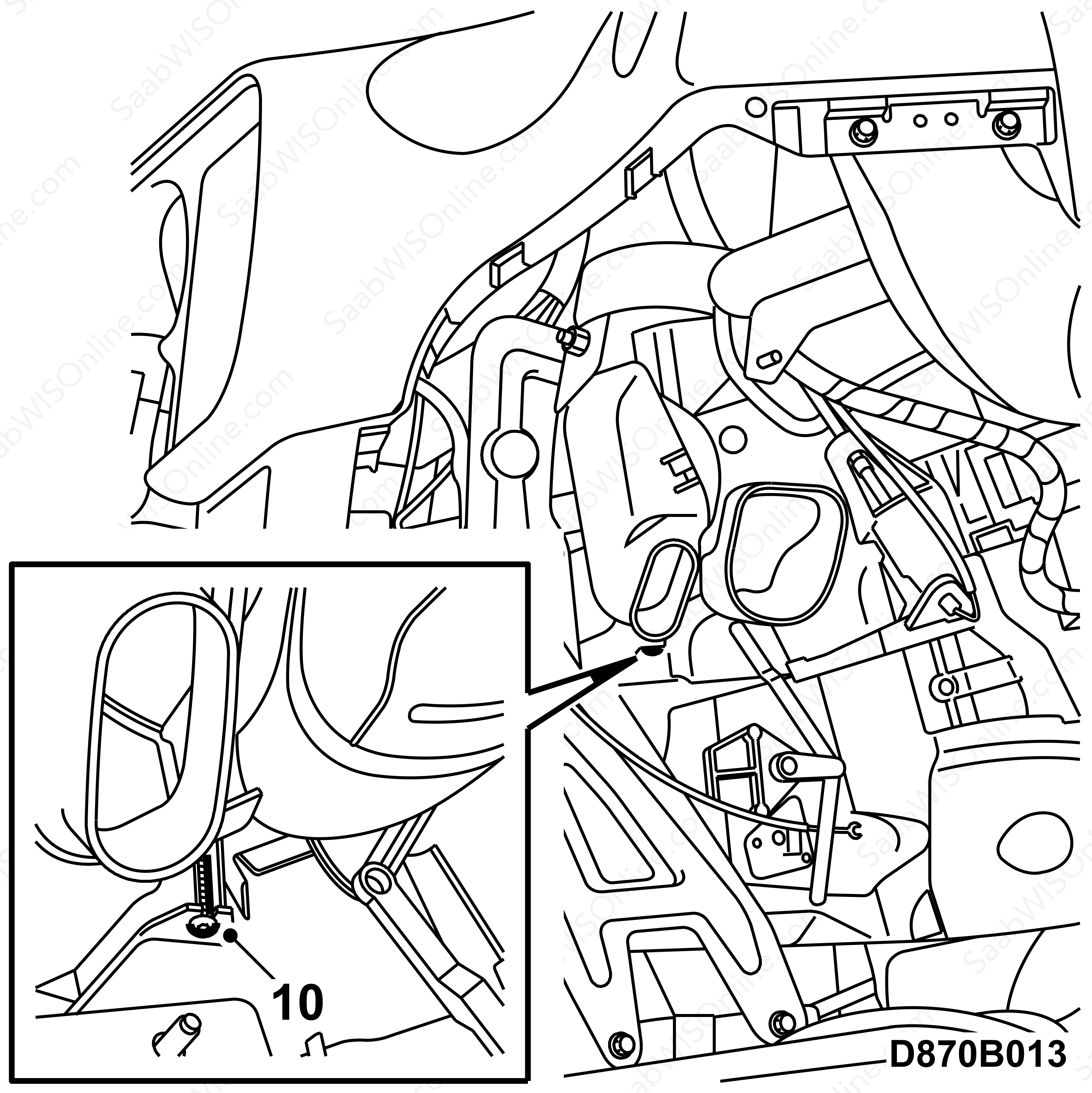
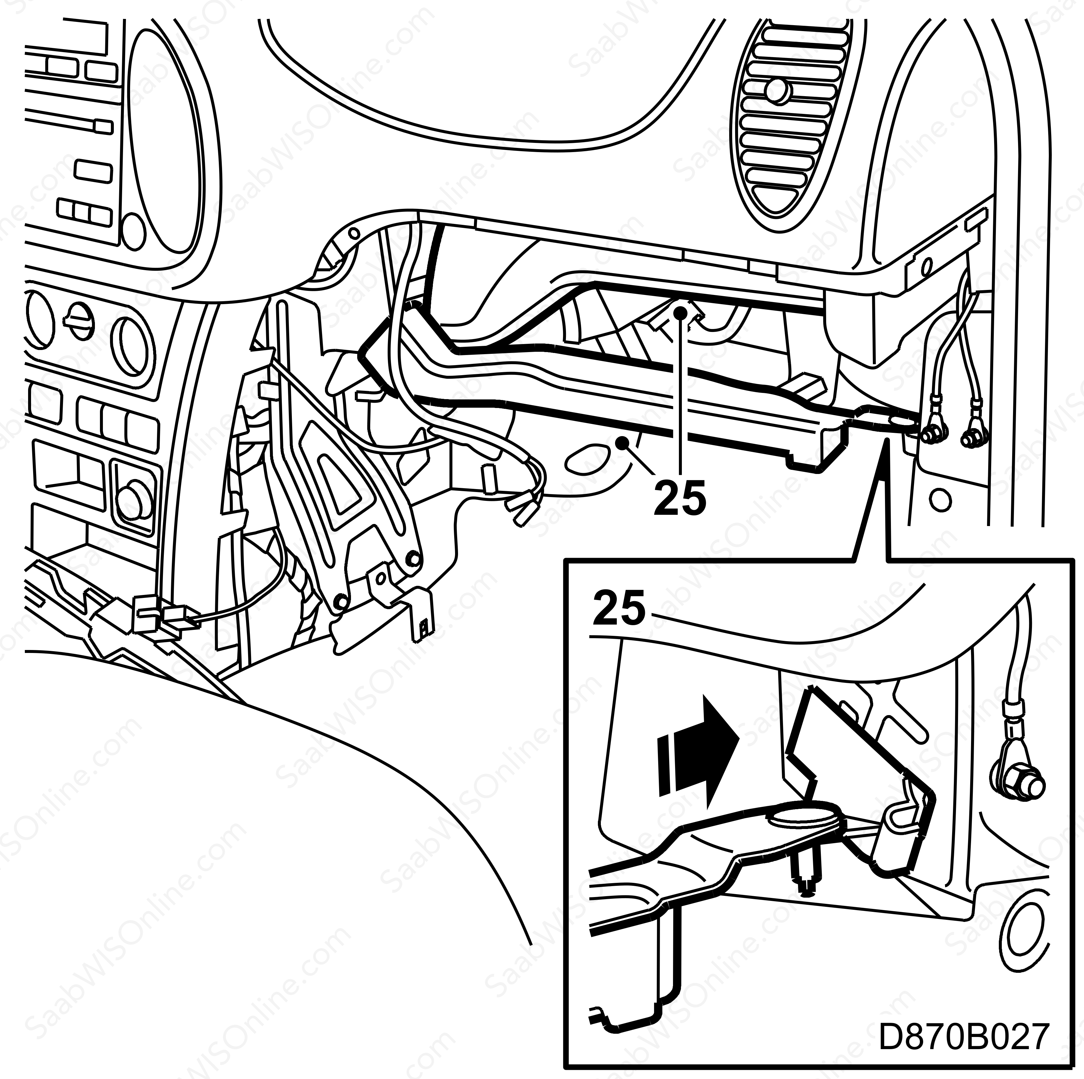
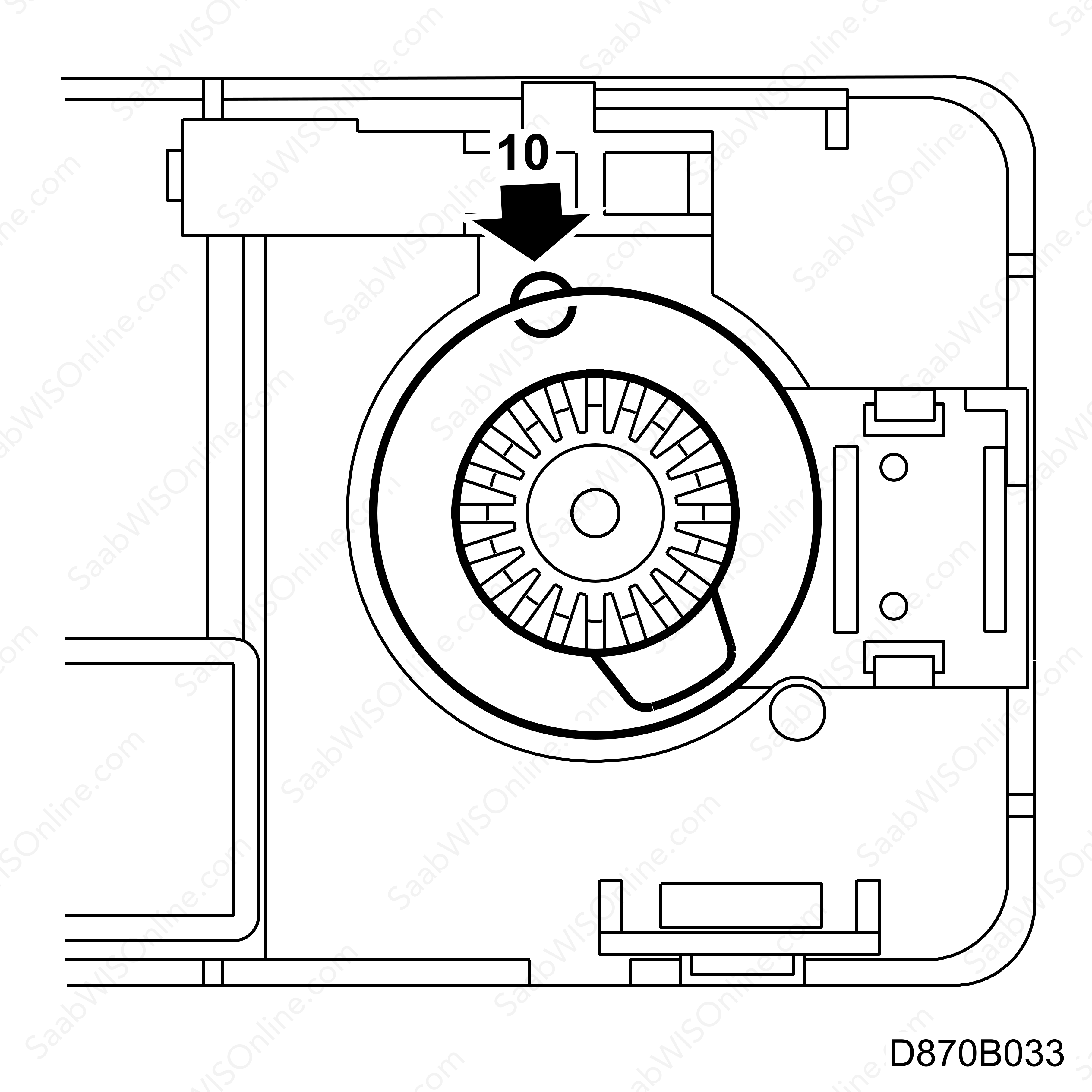
10.
|
Remove the screw on the right-hand side.
|
|
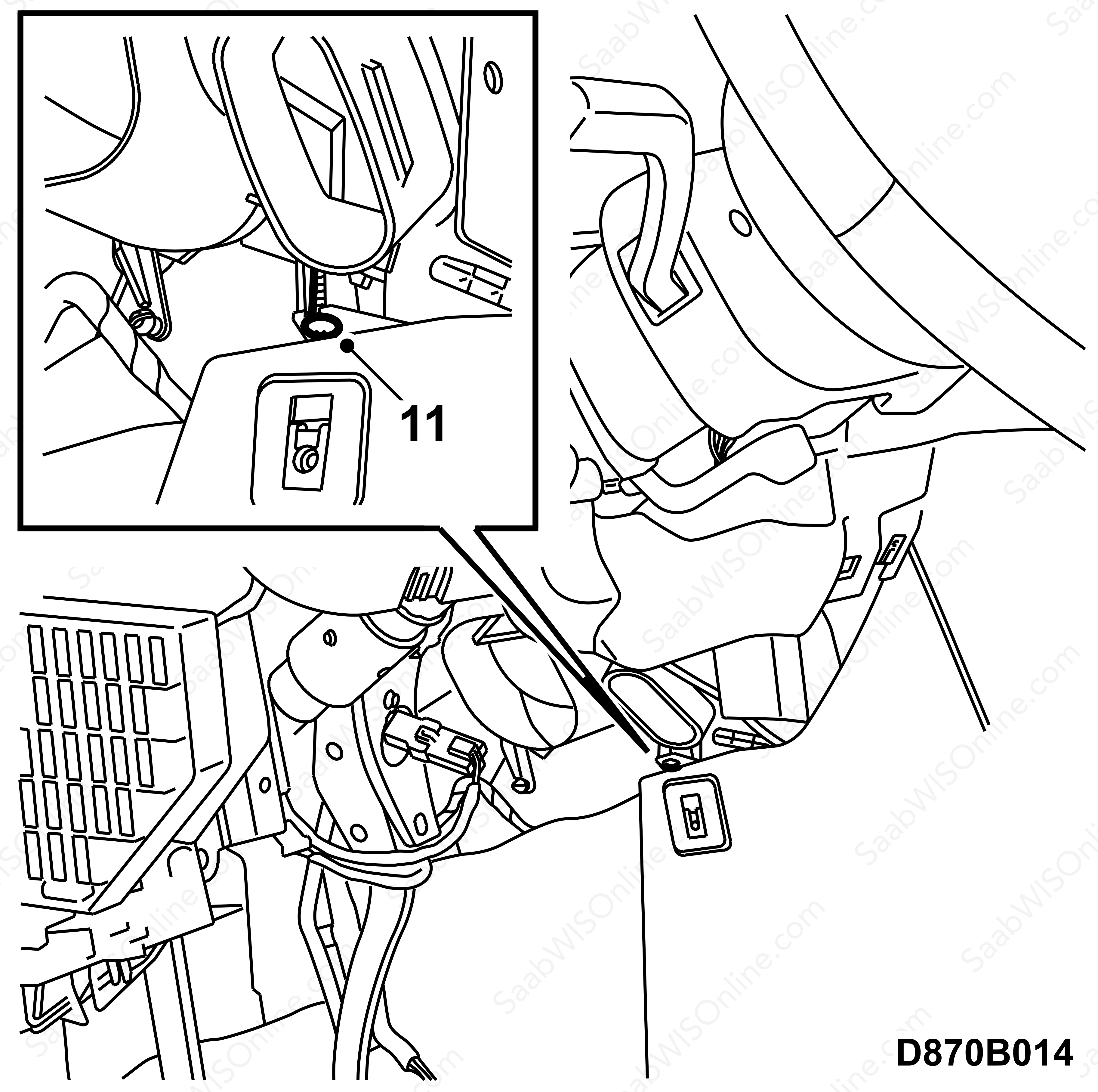
11.
|
Remove the screw on the left-hand side.
|
|
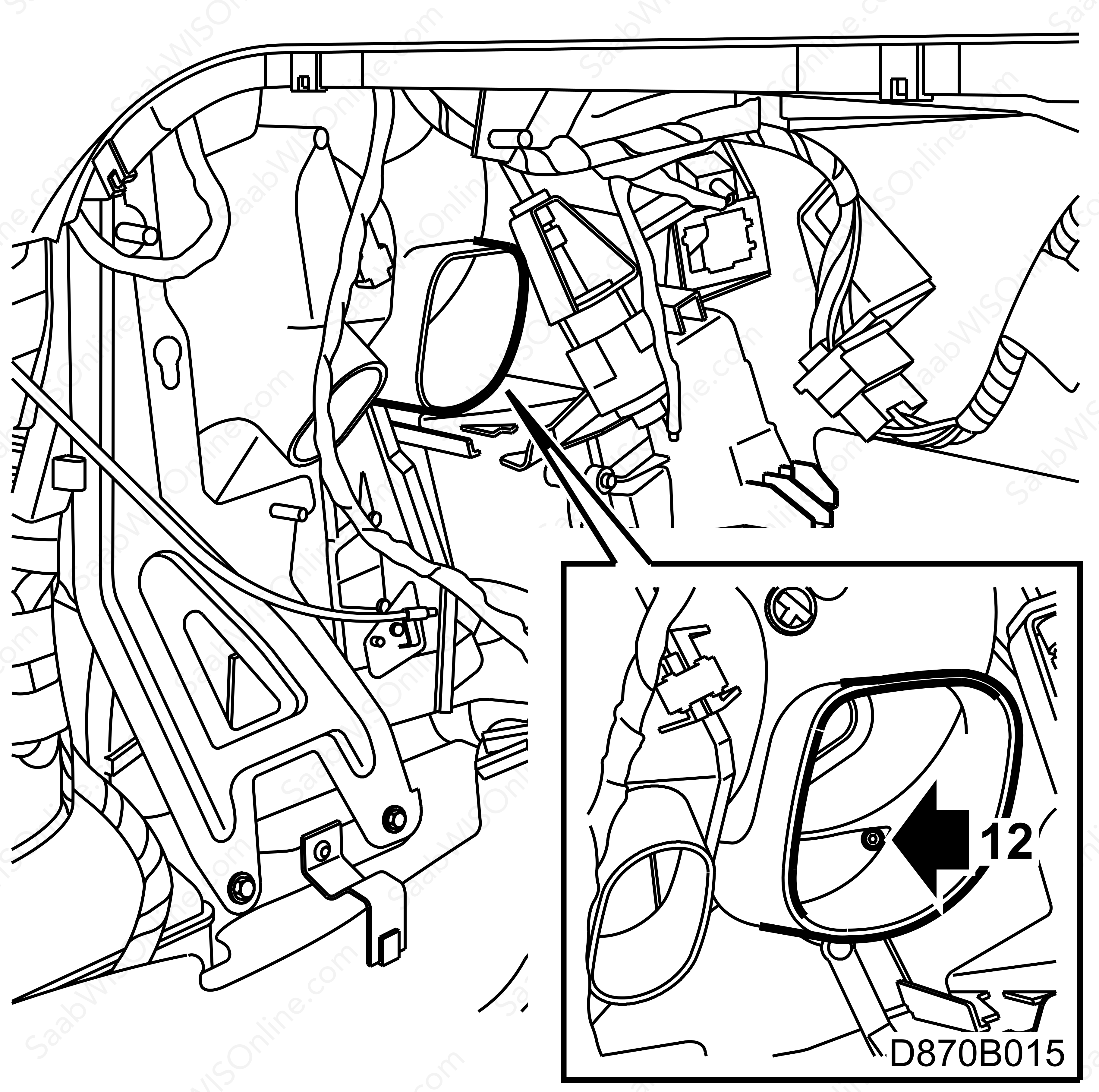
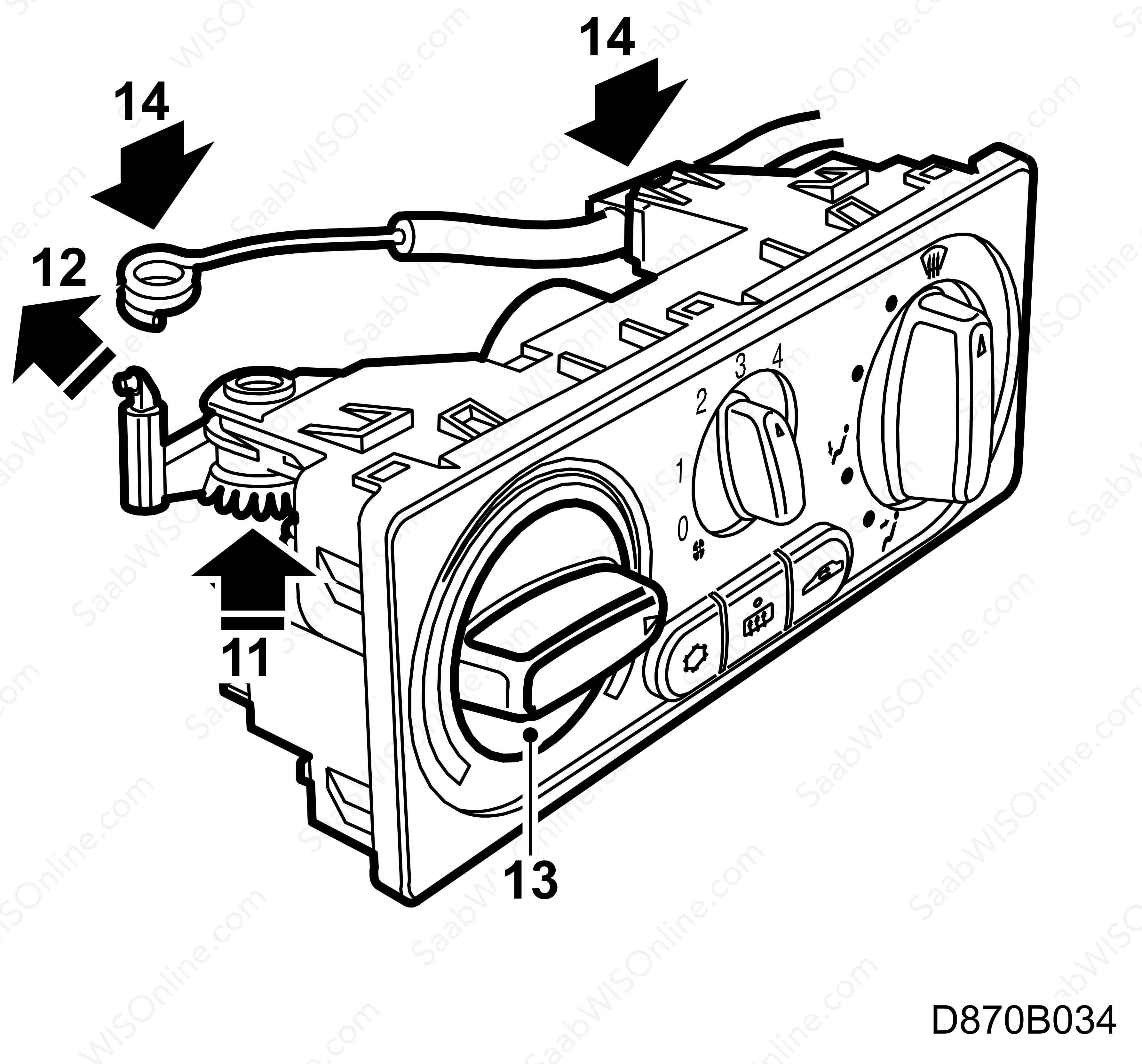
12.
|
In those cases where the car has been previously modified with screws as shown in the illustration, remove the screws and seal the holes with sealing compound 92 88 127 on both sides.
|
|
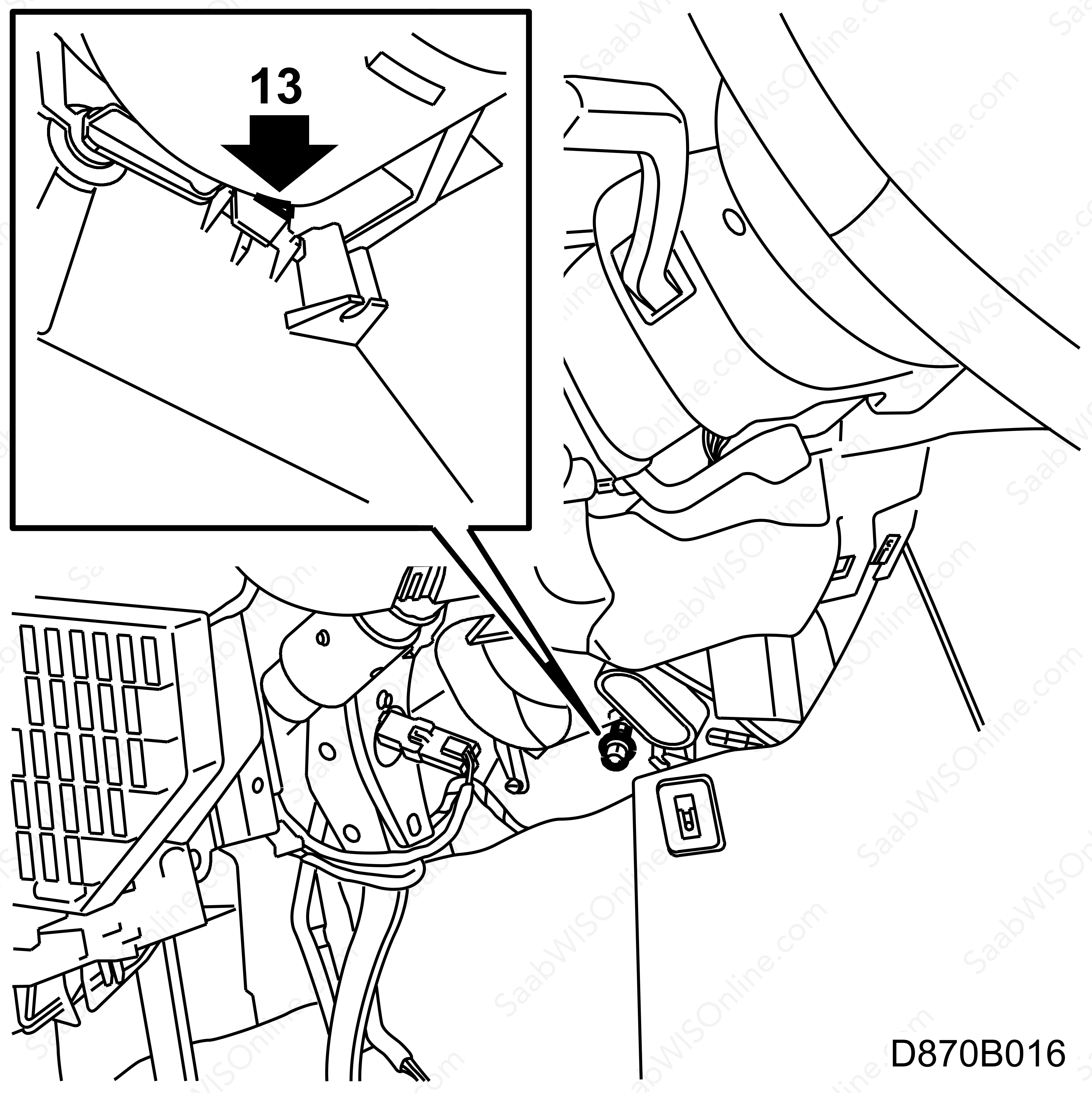
13.
|
Fit the new screw 79 76 897 on the car's left-hand side.
|
|
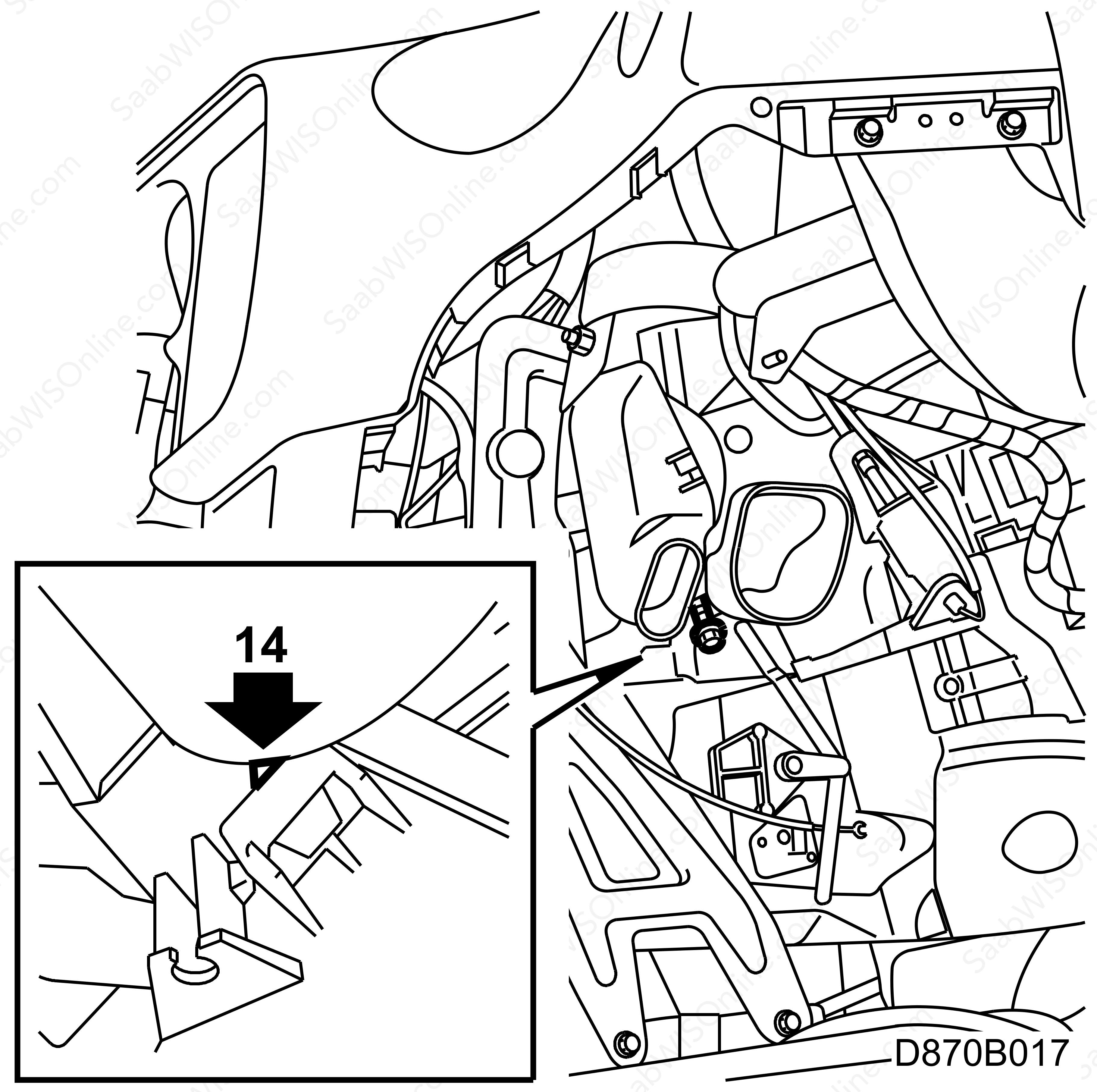
14.
|
Fit the new screw 79 76 897 on the car's right-hand side.
|
|
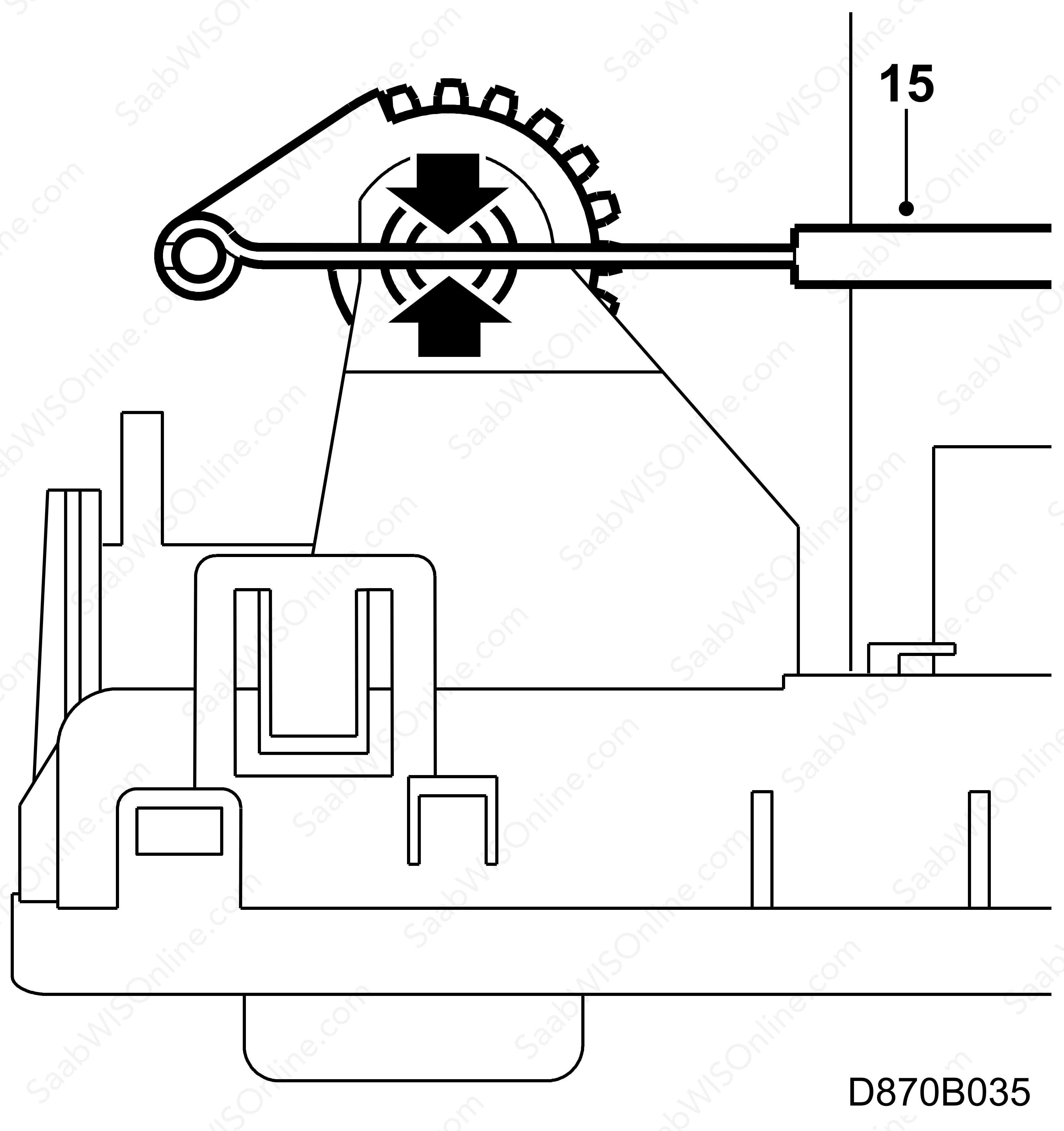
15.
|
Use a brush approx. 300 mm long and 10 mm wide when applying lubricant. Apply silicone grease 87 81 718.
|
|
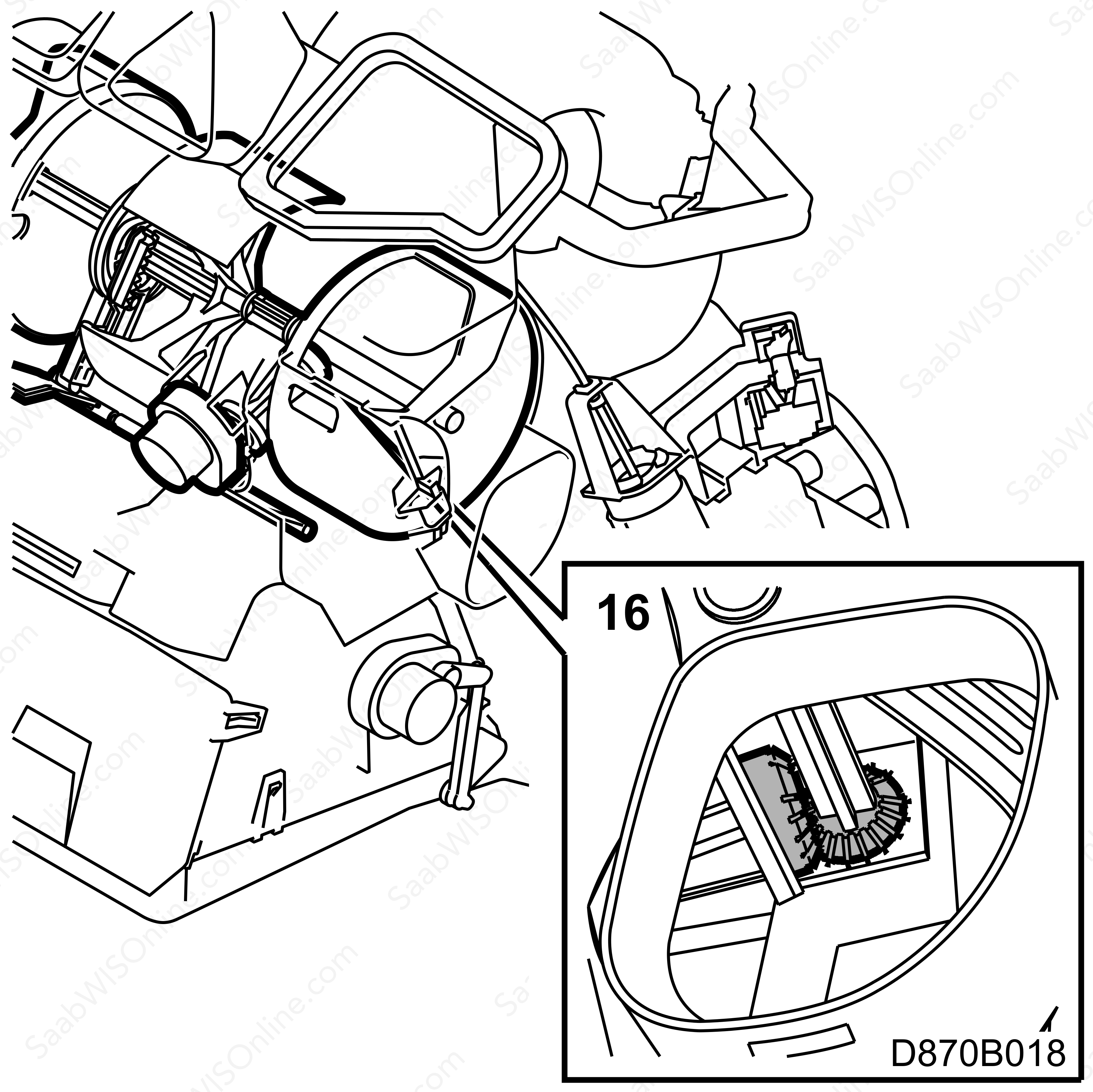
16.
|
Grease the angle gear from the right-hand side as shown in the illustration.
|
|
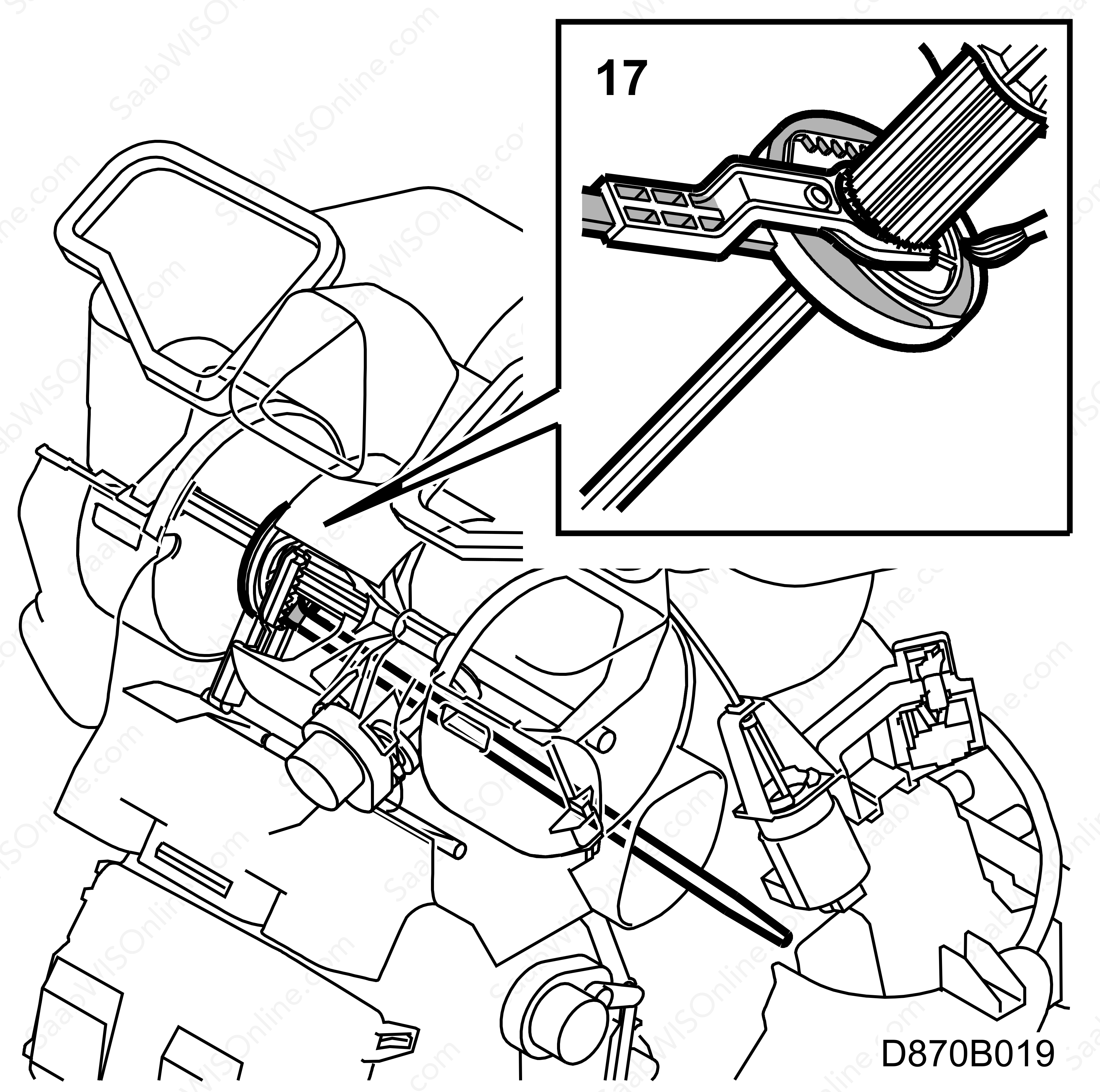
17.
|
Grease all moveable surfaces from the right-hand side as shown in the illustration.
|
|
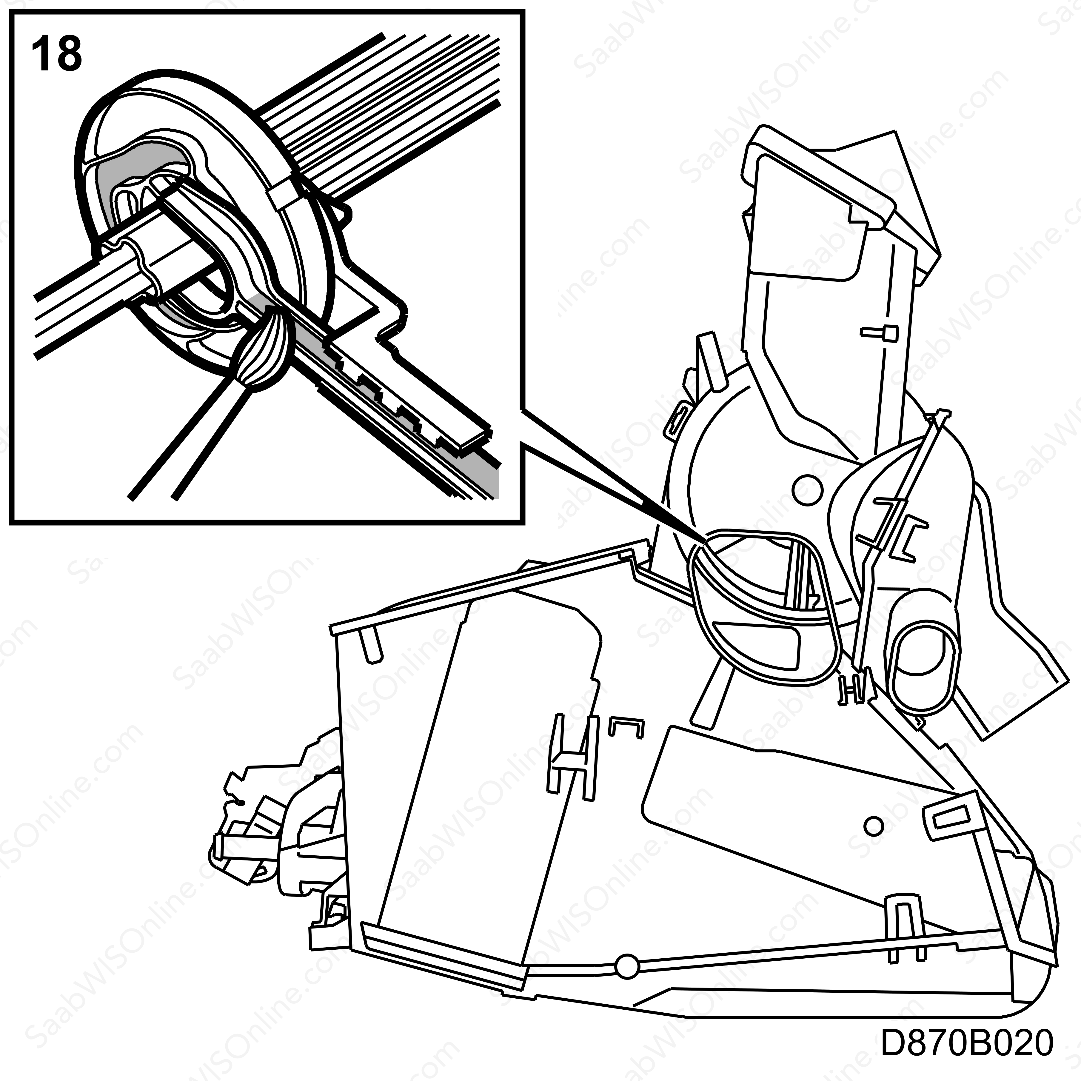
18.
|
Grease all moveable surfaces from the left-hand side as shown in the illustration.
|
|
19.
|
Turn the temperature control knob to the max. heat setting. Grease the contact surface for the heating damper seal from the car's right-hand side.

|
|
20.
|
Turn the heating control knob to the max. cooling setting. Grease the contact surface for the heating damper seal.

|
|
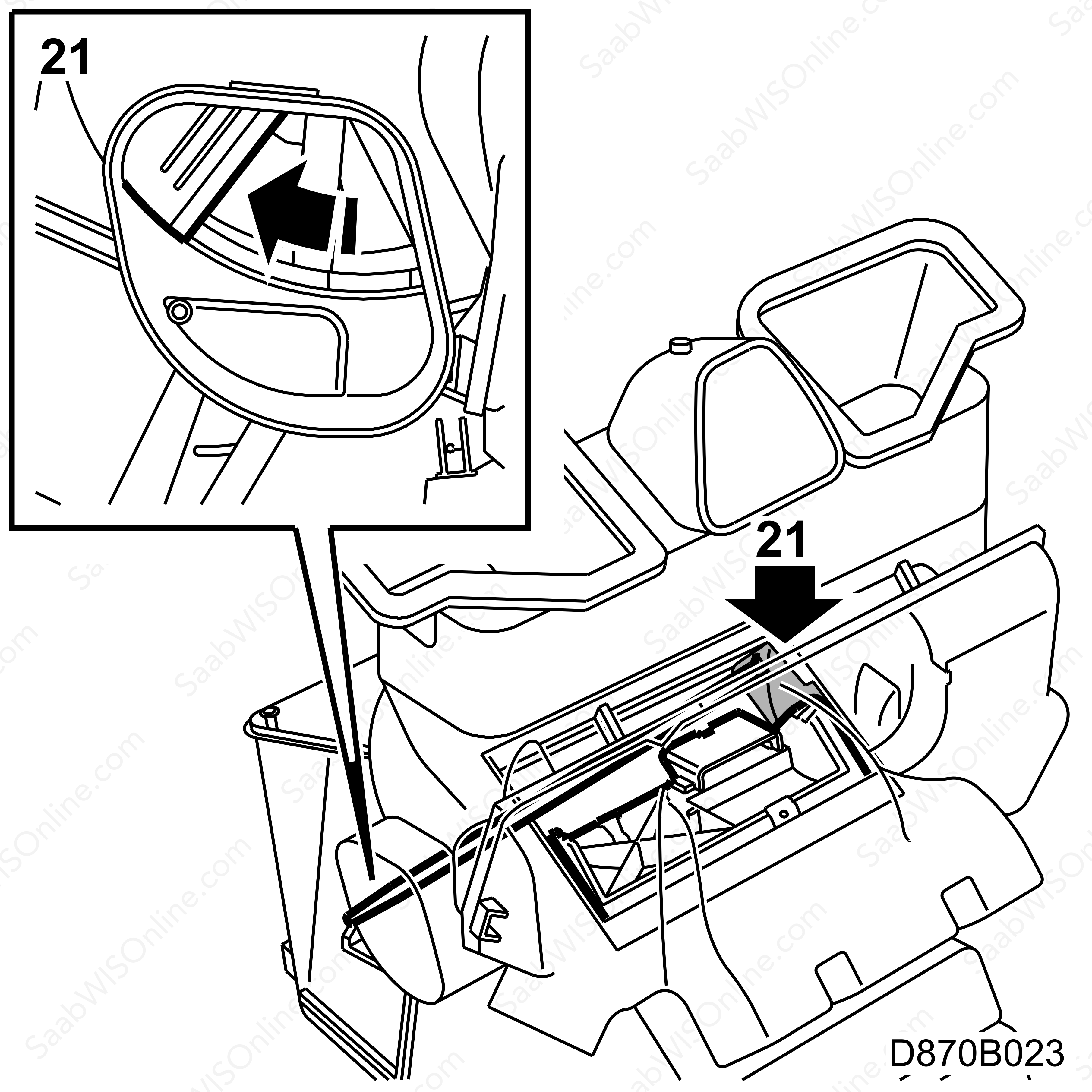
21.
|
Grease the contact surface for the heating damper seal from the car's left-hand side.
|
|
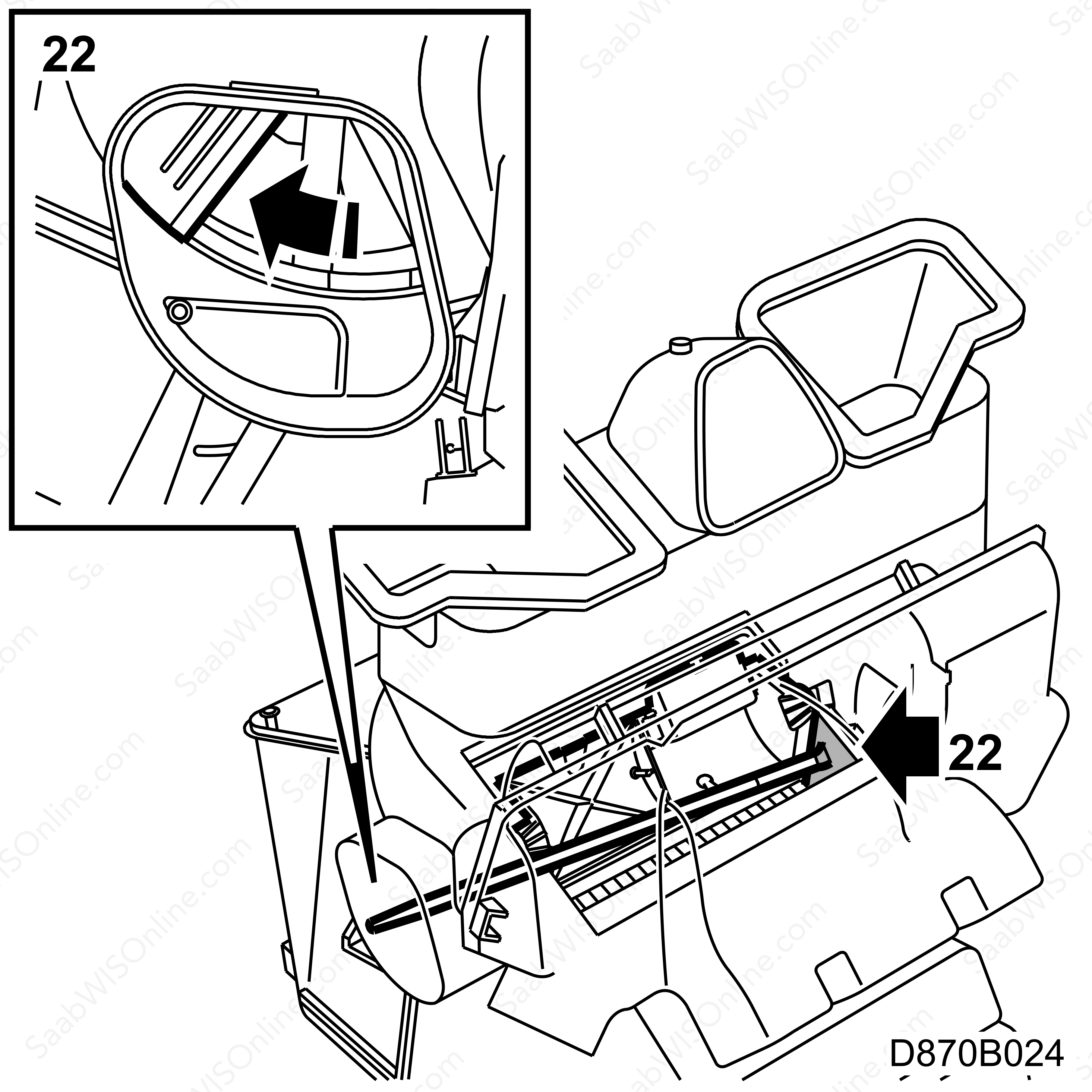
22.
|
Turn the heating control knob to the max. heat setting. Grease the contact surface for the heating damper seal as shown in the illustration.
|
|
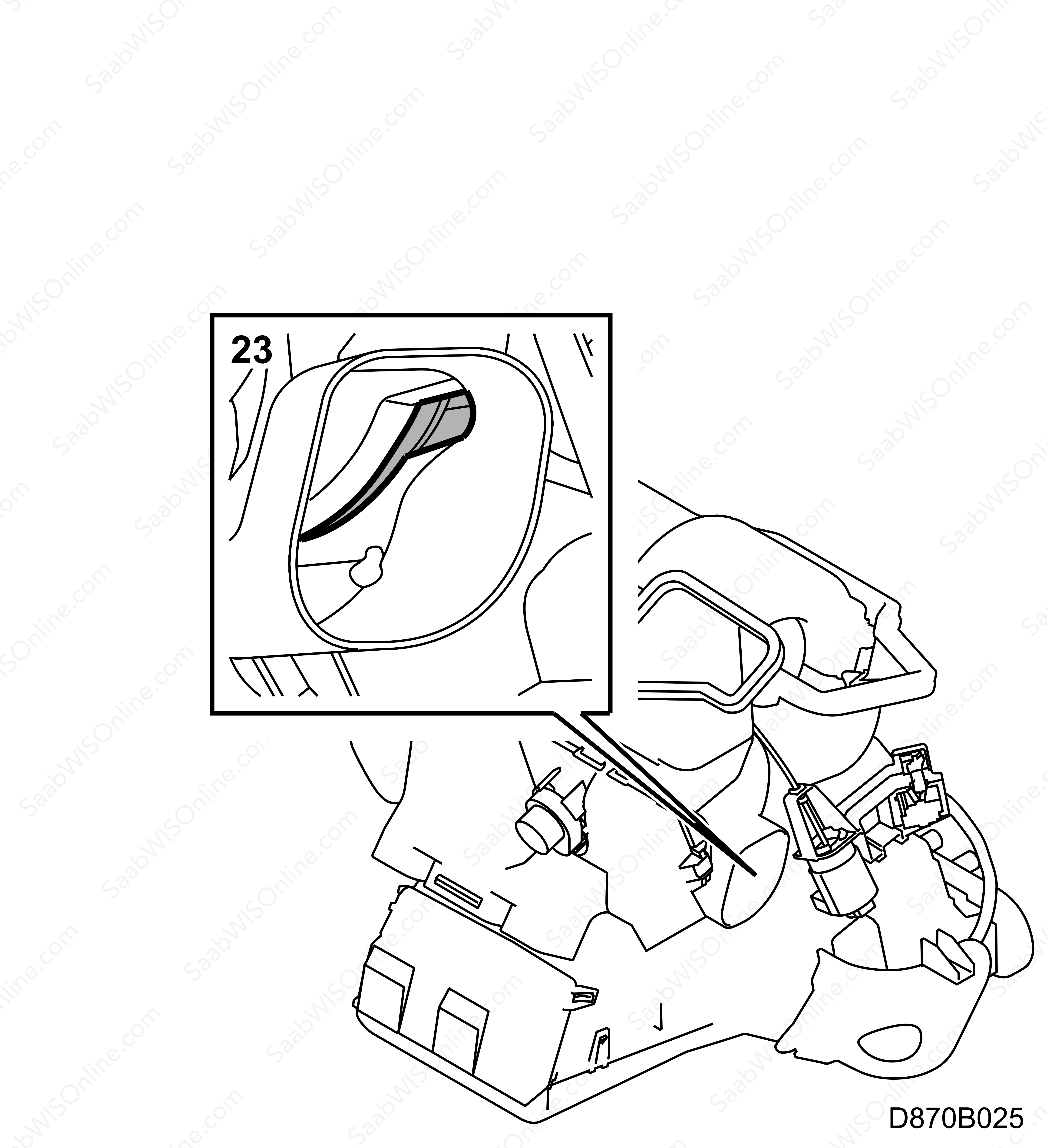
23.
|
Turn the air distribution control knob anti-clockwise until the arrow points down. Grease the housing near the drum from the car's right-hand side as shown in the illustration.
|
|
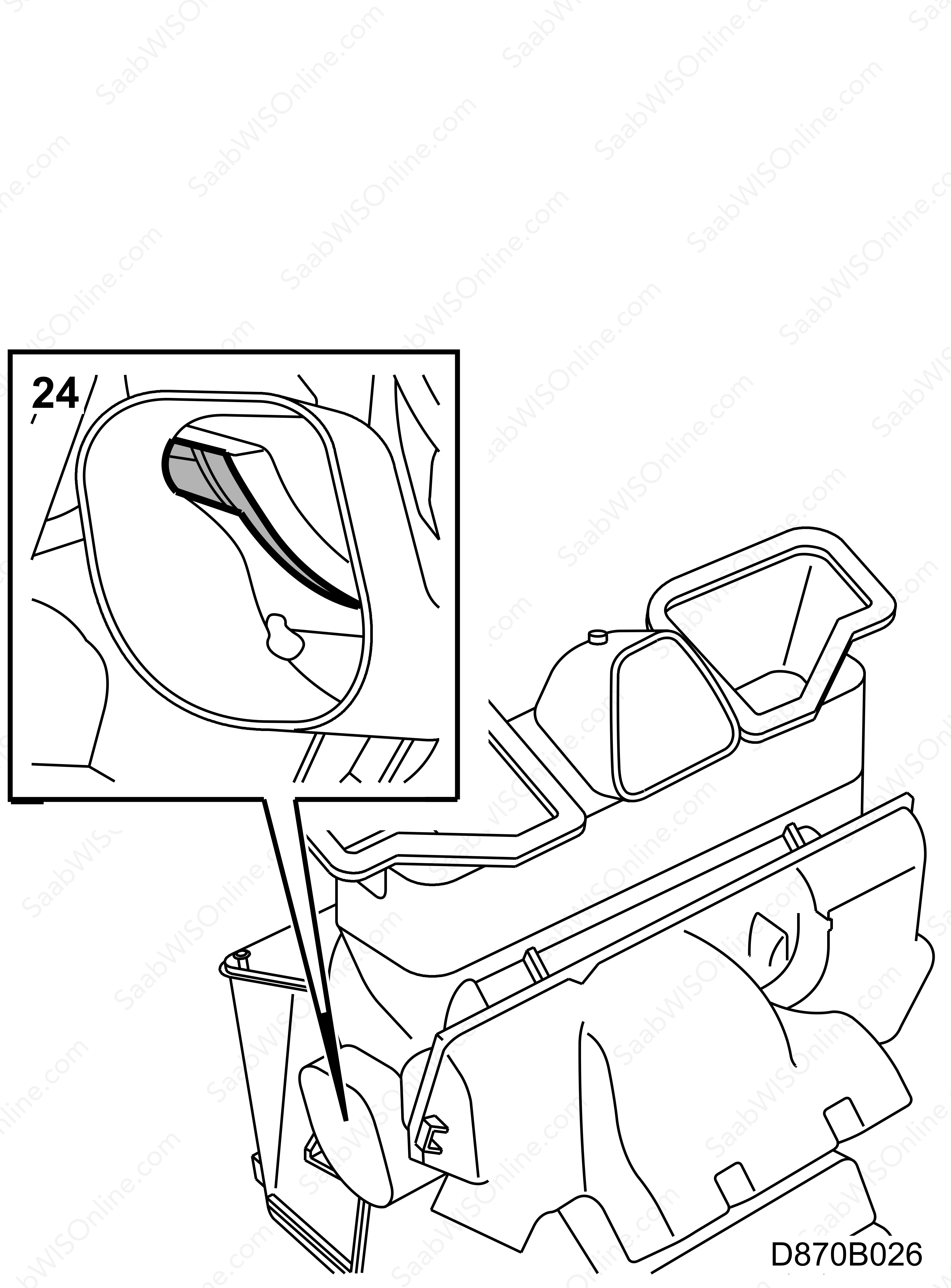
24.
|
Grease the housing near the drum from the car's left-hand side as shown in the illustration.
|
|
25.
|
Fit the air ducts on the passenger side.
|
|
26.
|
If necessary, fit the stay to the knee shield.
|
|
27.
|
Fit the centre console side panel.

|
|
29.
|
Fit the air duct to the dashboard vent on the driver's side.

|
|
31.
|
Fit the air duct to the floor vent.
|
|
32.
|
Fit the knee shield.
|
|
33.
|
Fit the lower dashboard section.
|
|
34.
|
Fit the data link connector.
|
|
35.
|
Clean the control panel.
|
Note
|
|
After the procedure is completed, the air distribution control knob may be difficult to manoeuvre in a horizontal position. This is not abnormal and is due to the heater's basic construction.
|
|
|
Replacing temperature control knob and shaft
|
|
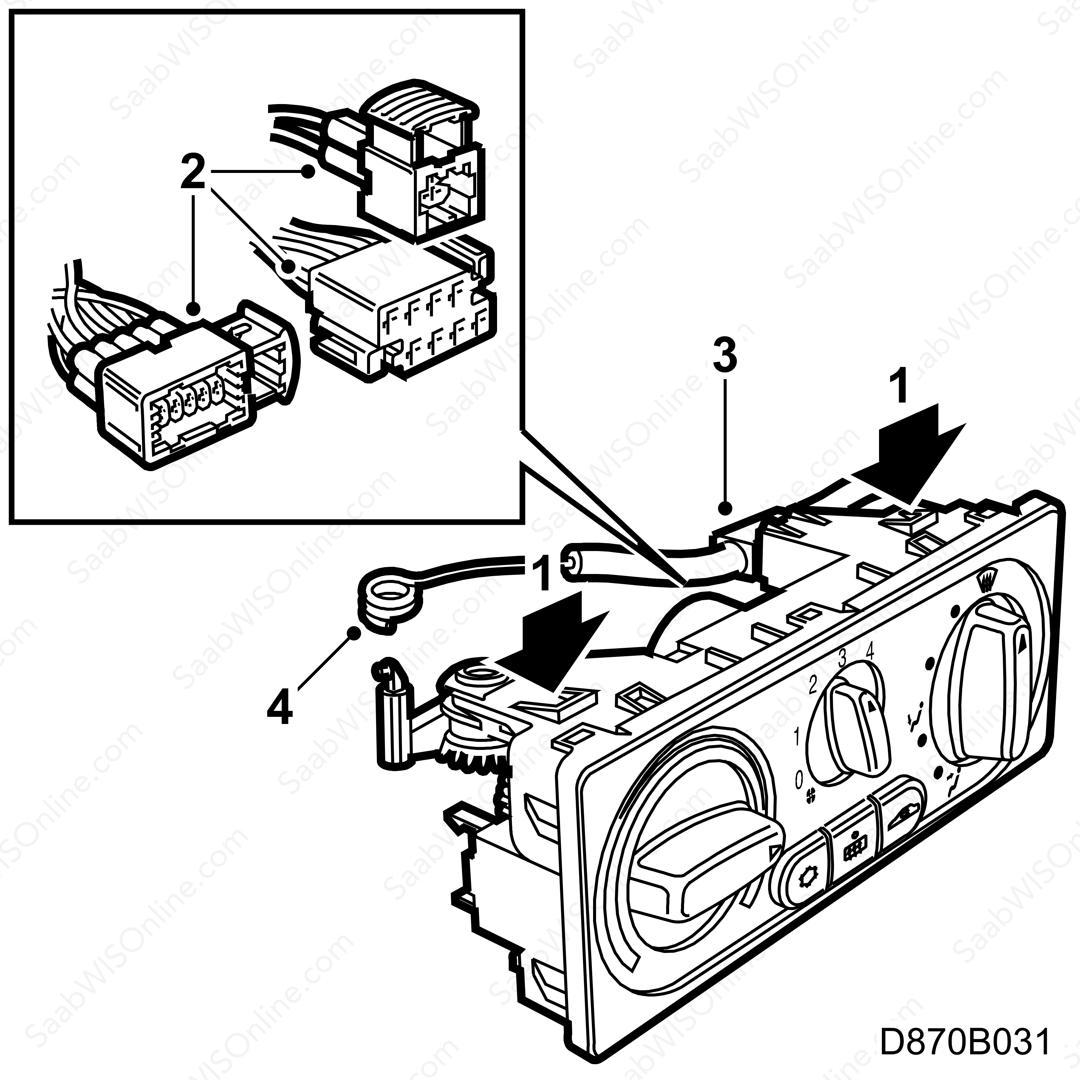
1.
|
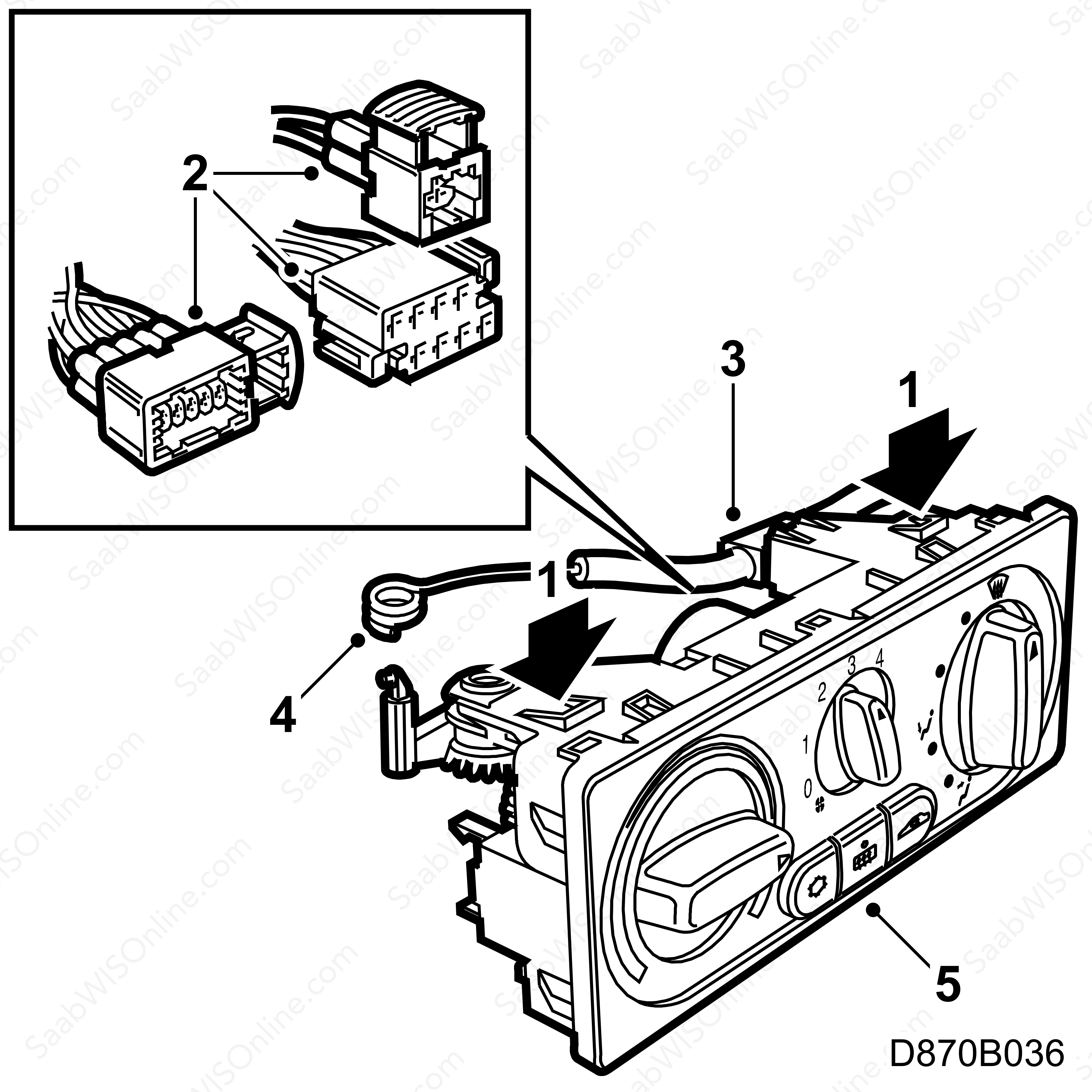
Remove the control panel from the rear. Push down the catches using a screwdriver.
|
|
2.
|
Unplug the connectors from the control panel.
|
|
3.
|
Remove the clips securing the cable to the control panel by pushing in the catches.
|
|
4.
|
Unhook the cable eye and lift out the control panel.
|
|
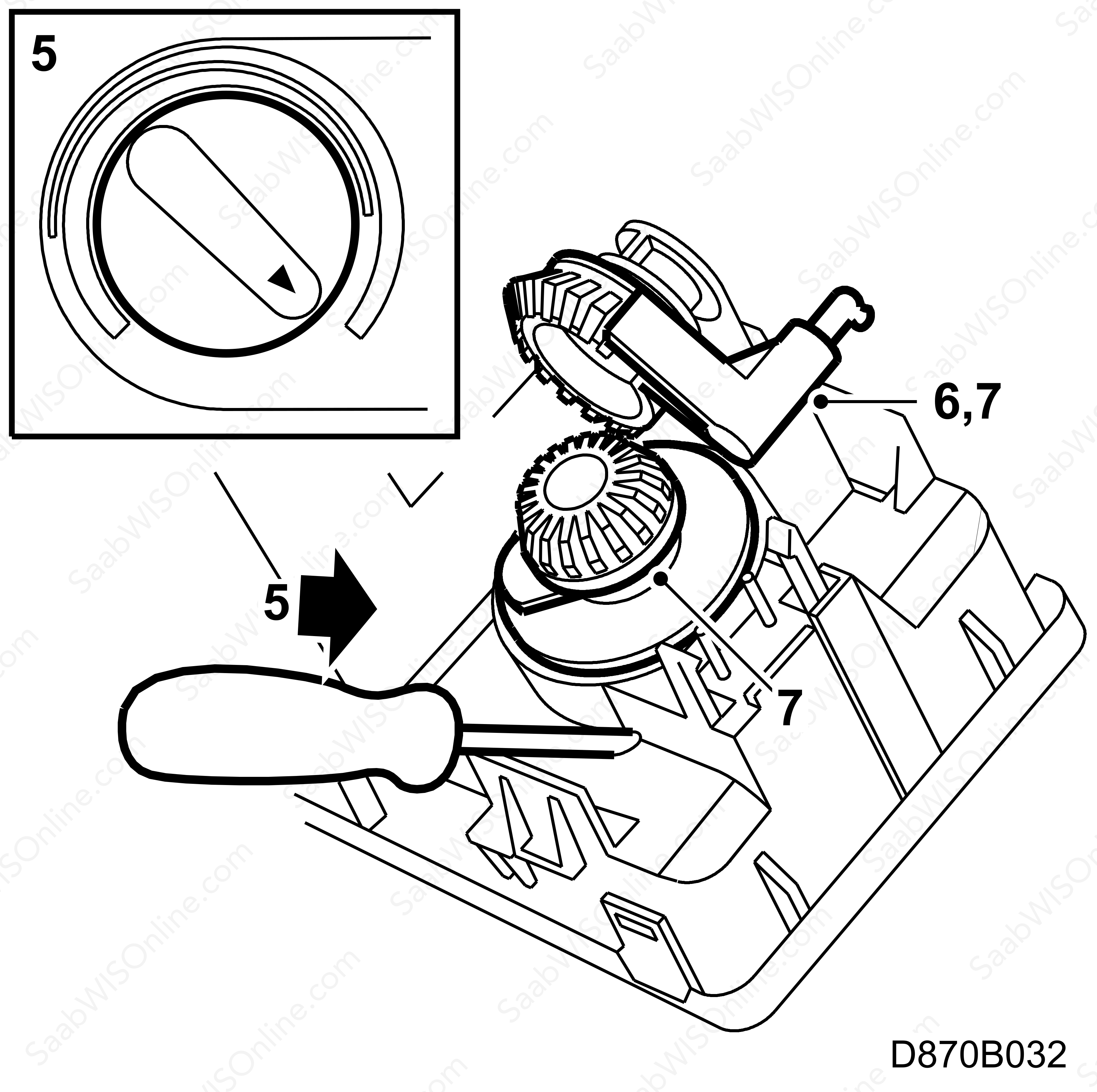
5.
|
Turn the temperature control knob to the max. heat setting and push out the knob through the small hole on the back side of the panel with a narrow screwdriver.
|
|
6.
|
Push the cable attachment lever towards the front of the panel so that the meshed gears holding the spindle shaft are released.
|
|
7.
|
Pull the lever downwards and out through the hole. Pull out the shaft through the side of the panel.
|
|
8.
|
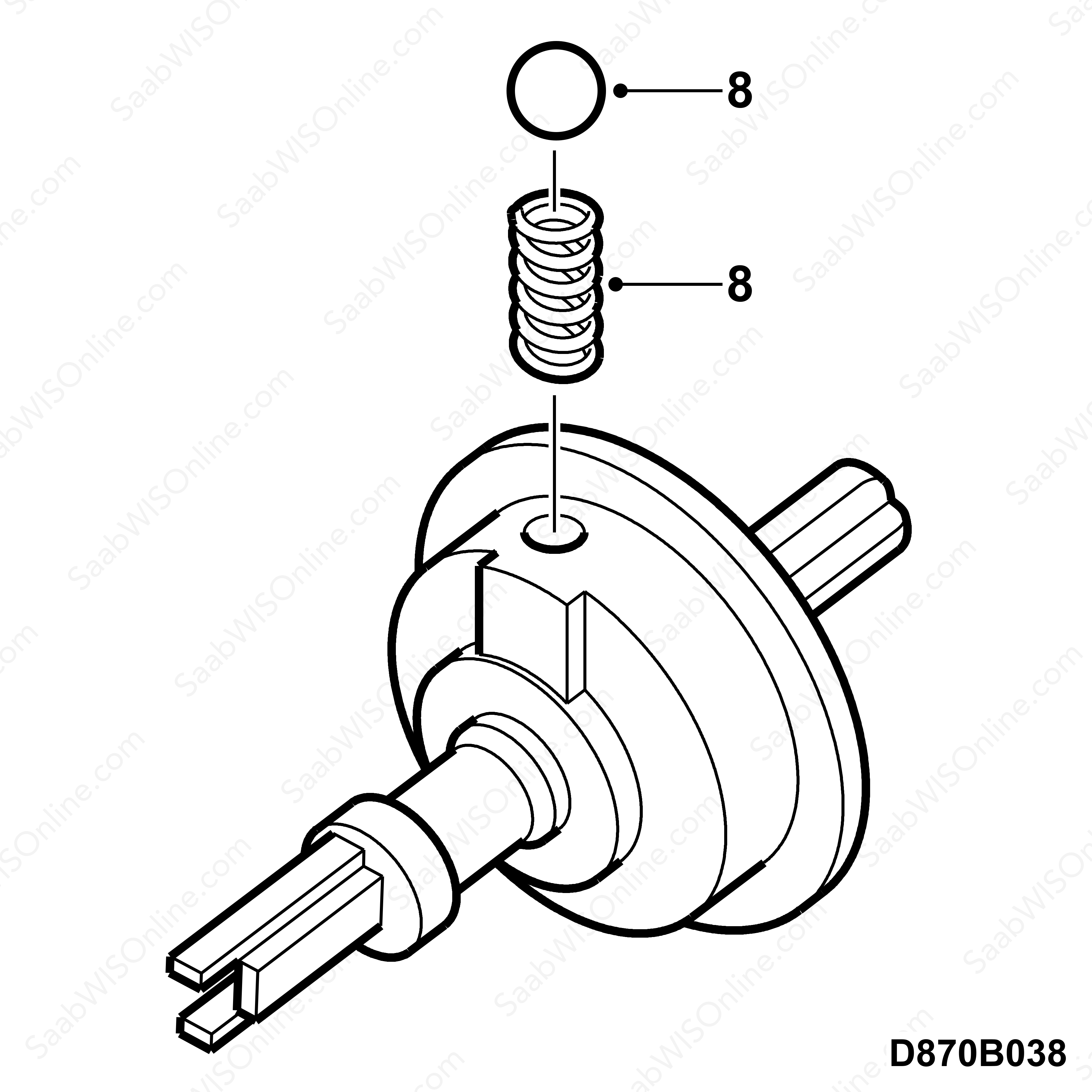
Recycle grease from the removed parts to lubricate the shaft and lever. Grease the gear rings and apply a small amount of grease to where the ball will be placed.
|
|
9.
|
First fit the spring to the shaft followed by the ball.
|
|
10.
|
Insert the shaft into the panel until the ball stops against the panel. Use a narrow screwdriver to depress the ball. At the same time, press in the shaft to snap it into the correct position.
|
|
11.
|
Fit the lever to the panel.
|
|
12.
|
Turn the lever clockwise (from an overhead perspective) until it snaps into the correct position.
|
|
13.
|
Fit the temperature control knob.
|
|
14.
|
Attach the cable to the panel.
|
|
15.
|
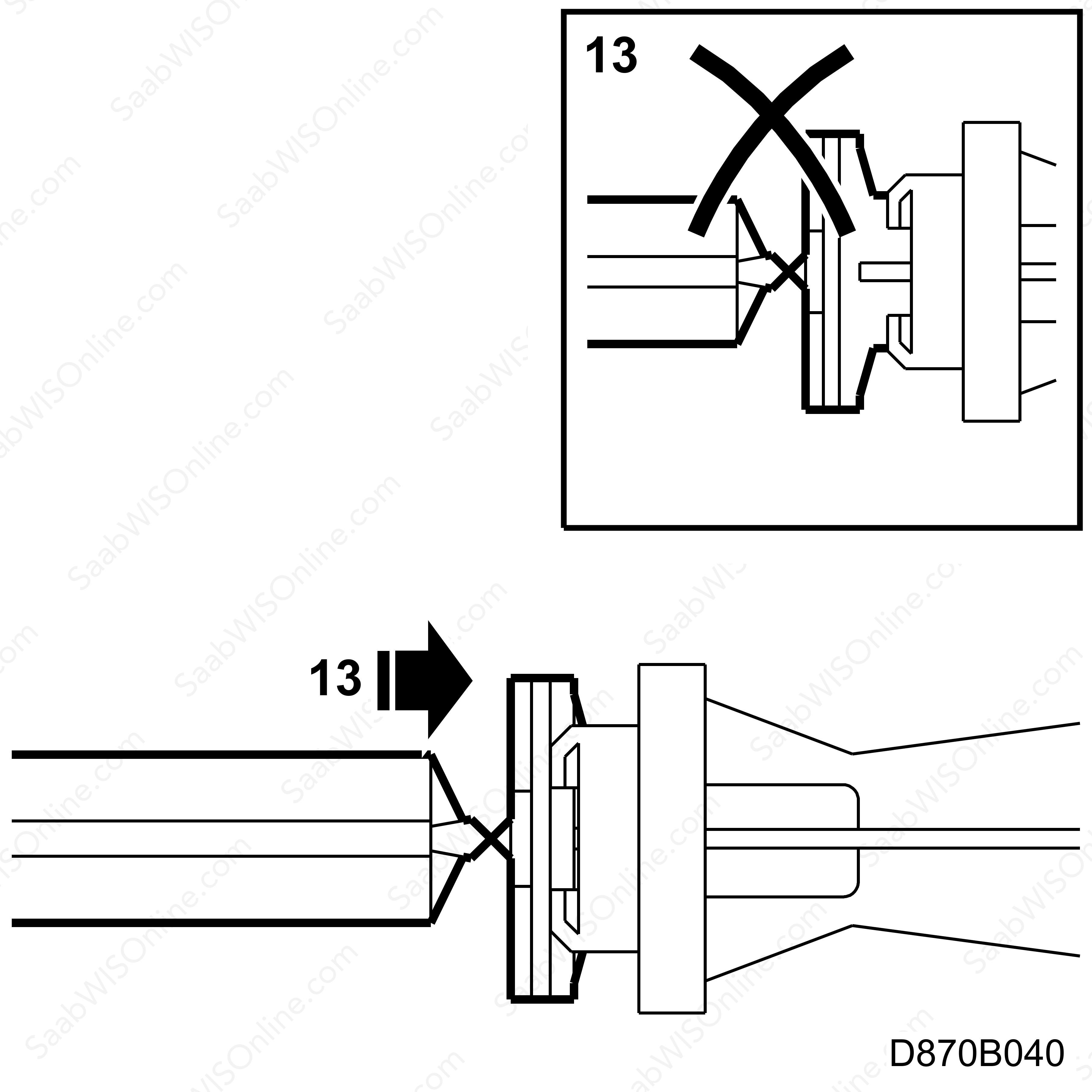
Check that the gears are in the correct position by turning the knob to the max. heat setting. The cable should run in a straight line from its attachment point, through the centre of the lever hole towards the clip plate.
|
|
16.
|
Plug in the connectors.
|
|
17.
|
Fit the control panel and control shaft.
|
|
18.
|
Return to step 9b under "Procedure".
|
|
Replacing the air distribution control knob shaft
|
|
1.
|
Remove the control panel from the rear. Push down the catches using a screwdriver.
|
|
2.
|
Unplug the connectors from the control panel.
|
|
3.
|
Remove the clips securing the cable to the control panel by pushing in the catches.
|
|
4.
|
Unhook the cable eye and lift out the control panel from the car.
|
|
5.
|
Remove the air distribution control knob.
|
|
6.
|
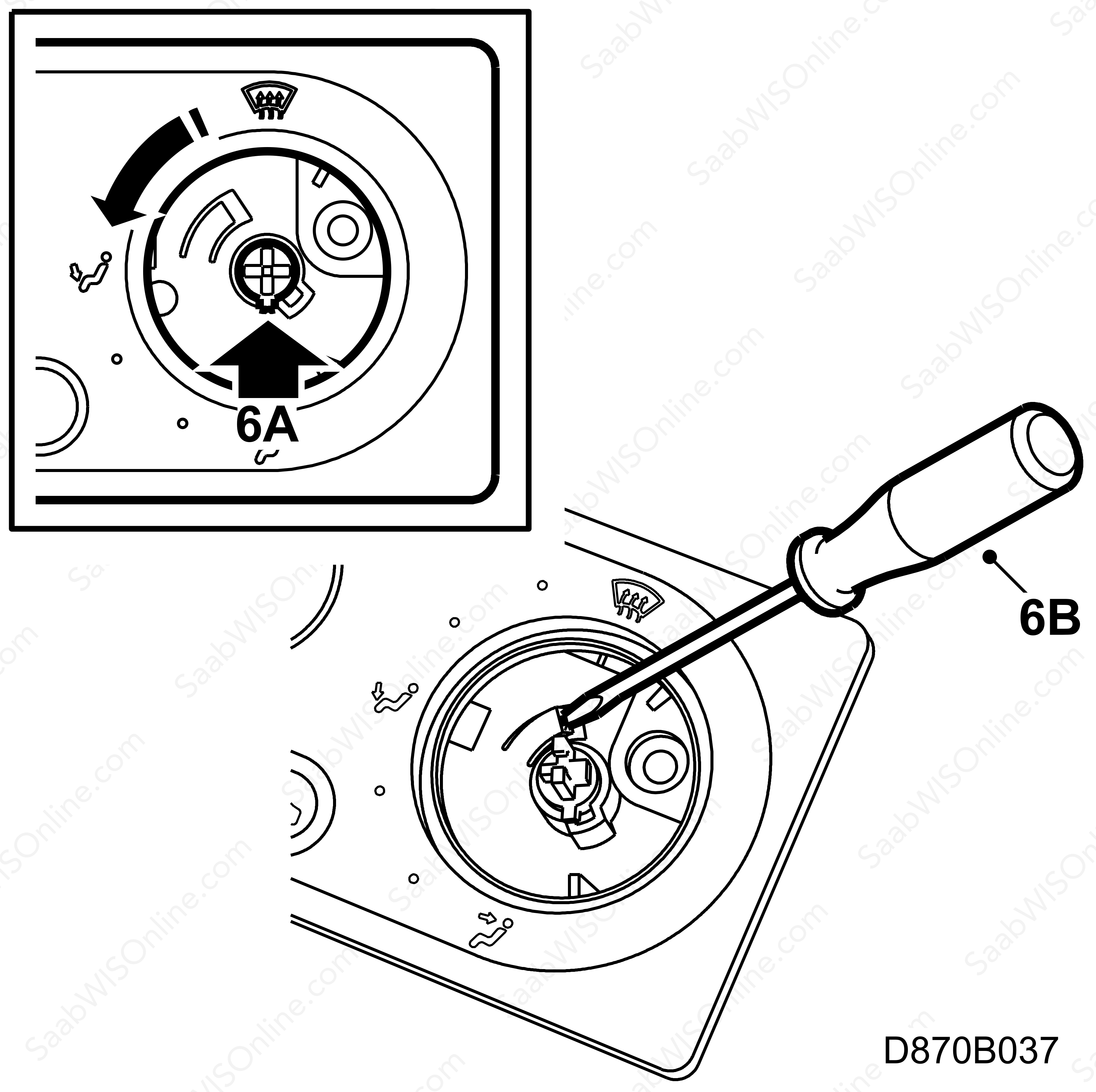
Remove the control shaft by
|
|
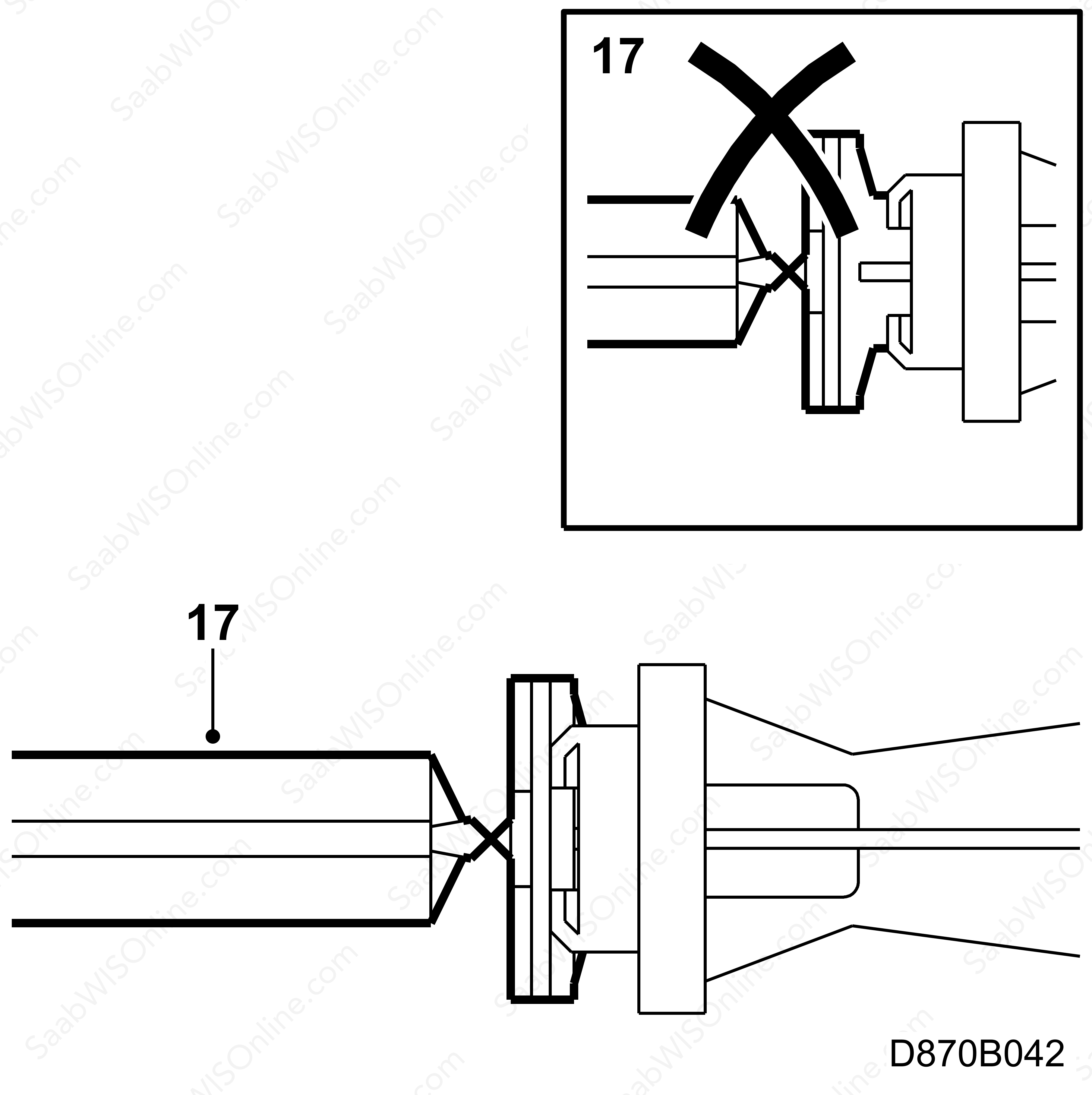
|
6.a.
|
turning it anti-clockwise (seen from the front side of the panel) until the guide pin is in the same position as shown in the illustration.
|
|
|
6.b.
|
carefully insert the locking tab using a screwdriver and turn the shaft anti-clockwise until the guide pin is located in the centre of the groove.
|
|
|
6.c.
|
carefully pull the control shaft out; retrieve the ball and spring.
|
|
7.
|
Recycle the grease from the removed shaft and apply it to the new shaft.
|
|
8.
|
Fit the spring and ball to the new shaft.
|
|
9.
|
Insert the shaft to the control panel. Use a screwdriver to hold the ball in place. Turn clockwise from the front side of the panel and make sure the locking tab locks.

|
|
10.
|
Position the control cable on the back side of the panel. The cable should be positioned above the control shaft.
|
|
11.
|
Fit the control knob.
|
|
12.
|
Plug in the connectors.
|
|
13.
|
Position the control panel and fit the telescoping control shaft.
|
|
15.
|
Return to step 9c under "Procedure".
|
|
Time/Warranty information
|
Upon customer complaint for a vehicle
under warranty
, use the following information for claims:
Failed Object: 85453
Fault/Reason code: 27
Location code: 09 (US=9)
Warranty Type (US): 1
Repair/Action code: 07
Labour Operation (US):85453-02 (CA: D2507)
Time: 1.1 hrs.


