(432-2037) Shift-lock solenoid
|
MODIFICATION INSTRUCTION
|
|
Bulletin Nbr:
|
432-2037
|
|
Date:
...........
|
March 1999
|
|
Market:
|
US, CA
|
|
Customer satisfaction campaign 10473
|
Cars in stock should be rectified before delivery.
A personal communication must be sent to the owners of cars already delivered requesting them to get in touch with the nearest Saab garage as soon as possible to have the fault rectified.
Saab 9-3 M99- with automatic transmission and VIN within the interval
X2000001-X2023753 (3D/5D)
and
X7000001-X7020971 (CV)
Occasionally, it may be difficult to move the selector lever from the P-position on certain cars. This is due to a fault in the microswitch fitted to the Shift-lock solenoid. In order to move the selector lever to any other position than P, Shift-lock must be manually disengaged by pressing down the key in the hole next to the selector lever while the selector lever is moved to position N.
51 62 060 Shift-lock solenoid
Before taking any measures, box A4 on the modification identity plate must be checked. If the box has been marked, continue as follows:
|
1.
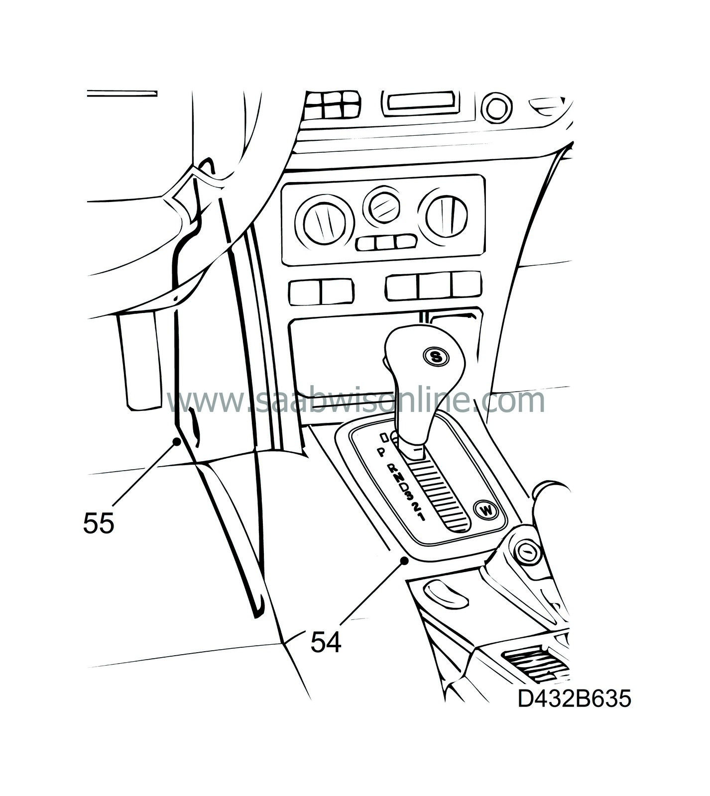
|
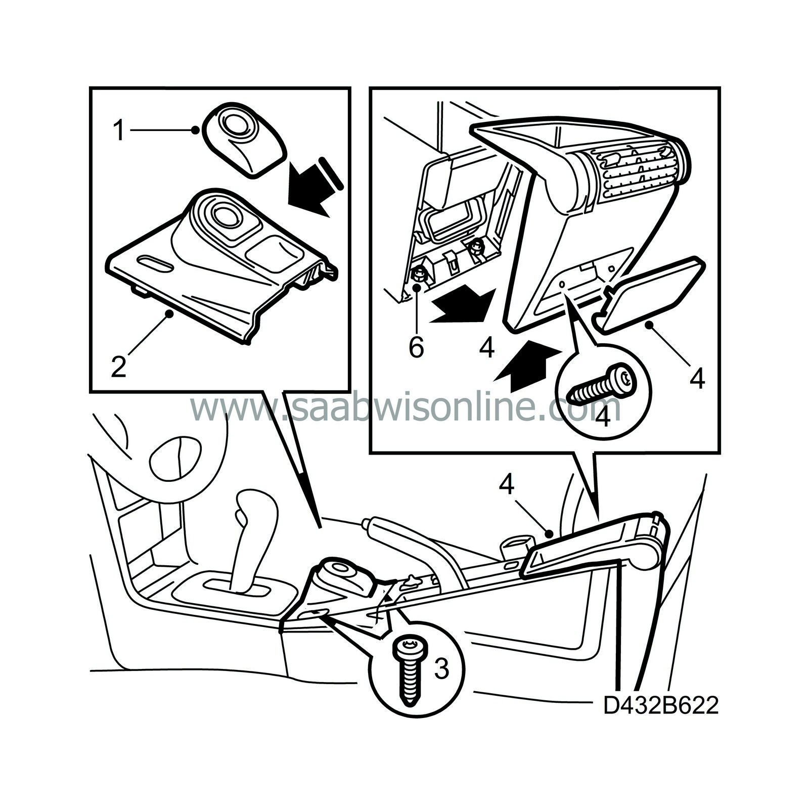
Apply the handbrake and remove the antenna unit by rotating it slightly clockwise and then lifting it up.
|
|
2.
|
Remove the ignition switch cover by loosening the back and the front left side of the cover. Then, unhook the front edge.
|
|
3.
|
Undo the floor console retaining screws.
|
|
4.
|
Remove the rear ashtray/cover.
|
|
5.
|
Remove the rear cover.
|
|
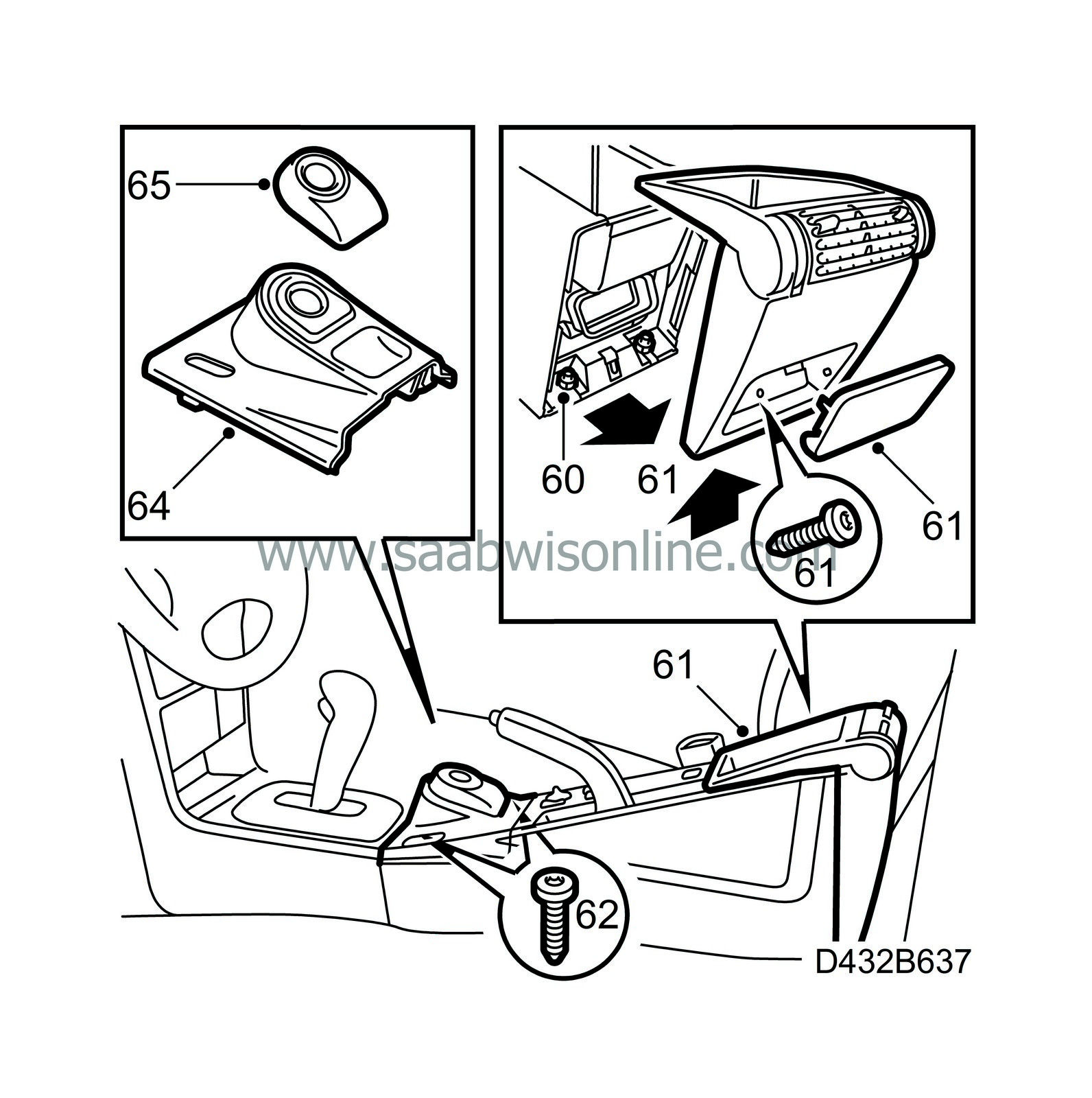
6.
|
Remove the floor console retaining nuts.
|
|
7.
|
Loosen the floor console by pulling it straight back and lifting up slightly.
|
|
8.
|
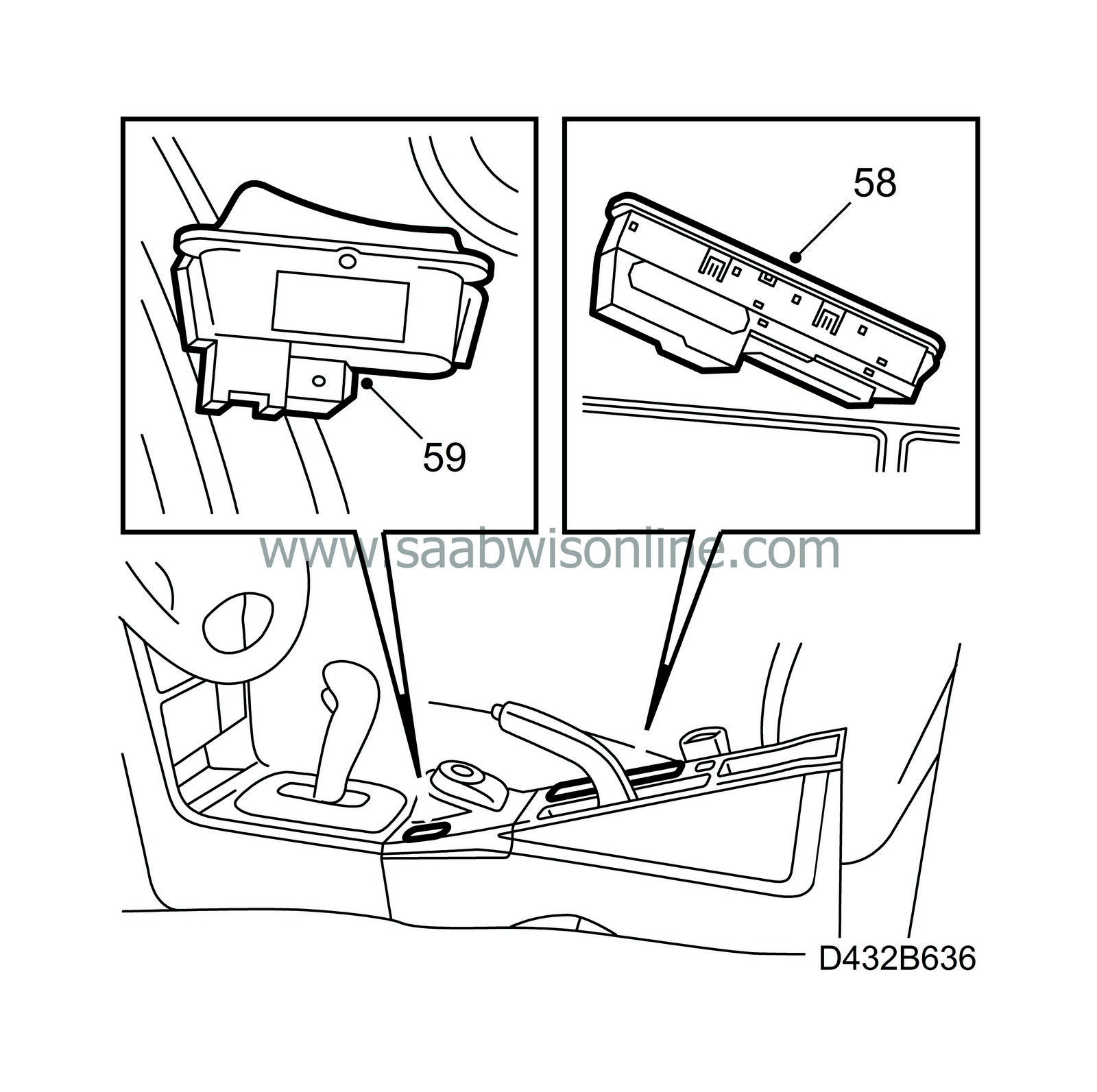
Convertible:
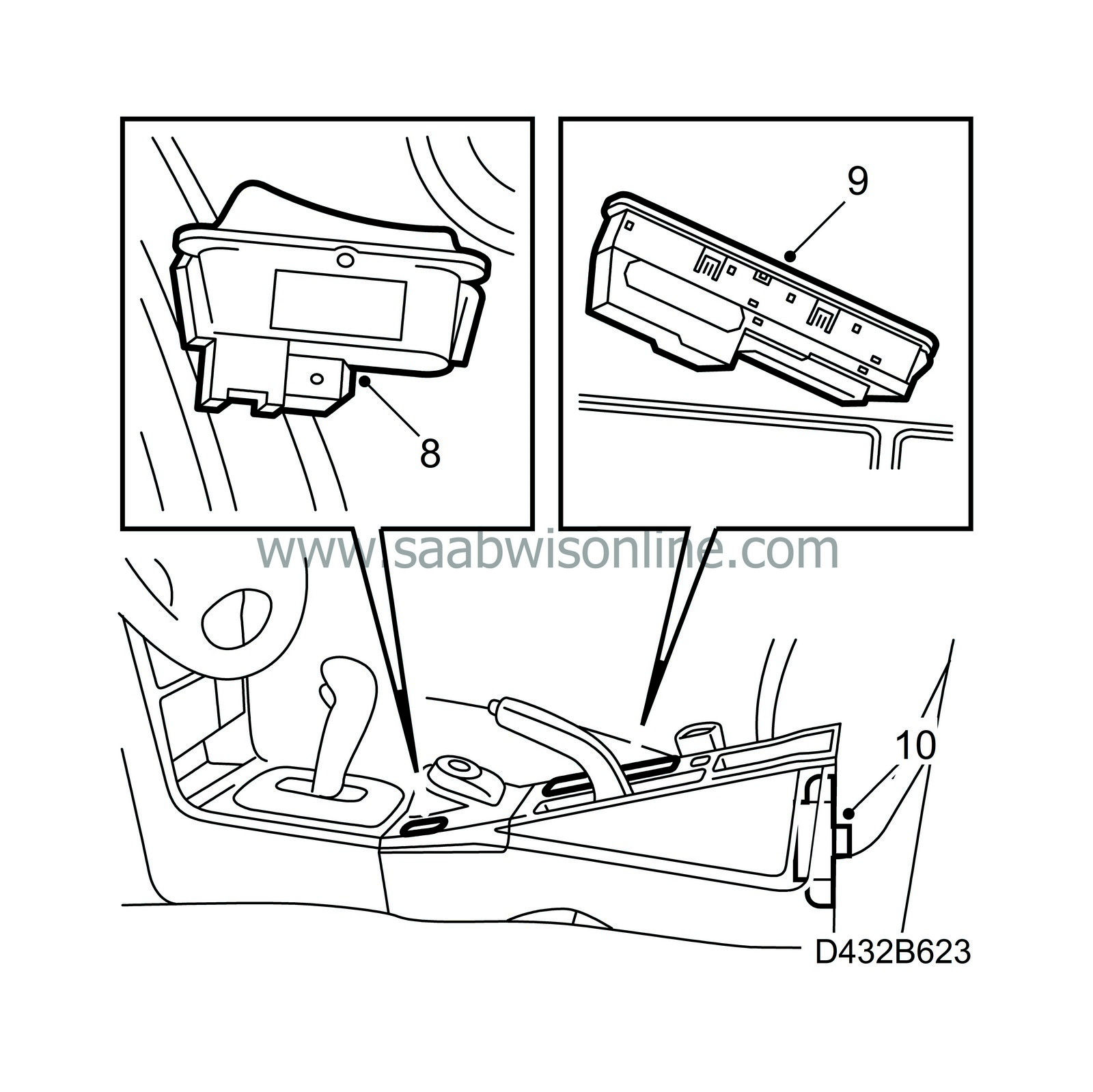
Remove the cabin lighting switch using a screwdriver or press it up from below, the switch is fastened with clips, and pull it straight up. Unplug the switch connector.
|
|
9.
|
Loosen the window lift module by loosening the front (snap fastener). Unplug the window lift module connector.
|
|
10.
|
Lift away the floor console.
|
|
11.
|
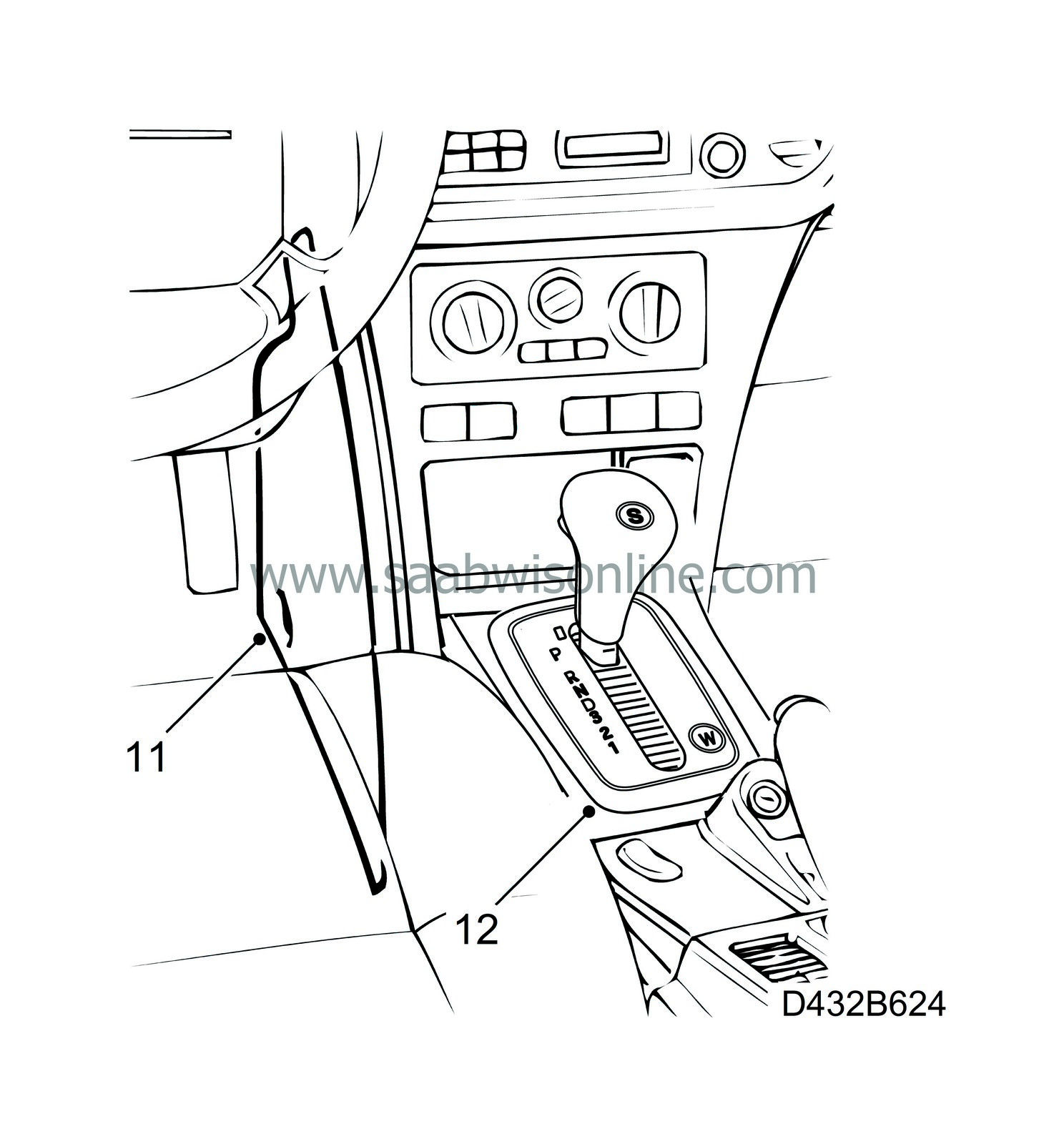
Remove right and left side pieces by undoing the retaining screws and sliding each piece out of the centre console.
|
|
12.
|
Remove the rim with a small screwdriver.
|
|
13.
|
Cars with ACC:
Press out the ACC module from behind and unplug the connector.

Cars without ACC:
Press out the heater control panel from behind.
|
|
14.
|
Cars without ACC:
Detach the air distribution shaft from the air distribution control.
|
|
15.
|
Cars without ACC:
Unplug the connector from the control panel.
|
|
16.
|
Cars without ACC:
Detach the cable from the control panel. It is fastened with an eyebolt and locked with a locking washer.
|
|
17.
|
Cars without ACC:
Remove the heater control panel.
|
|
18.
|
Unplug all the connectors in the centre console.
|
|
19.
|
Remove the expanding rivets securing the console to the dashboard by pressing in the centre pins 3 mm and pulling out the rivet. Use removal tool 84 71 179.
|
|
20.
|
Lift out the centre console.
|
|
21.
|
Detach the air duct to the rear air vent
|
|
22.
|
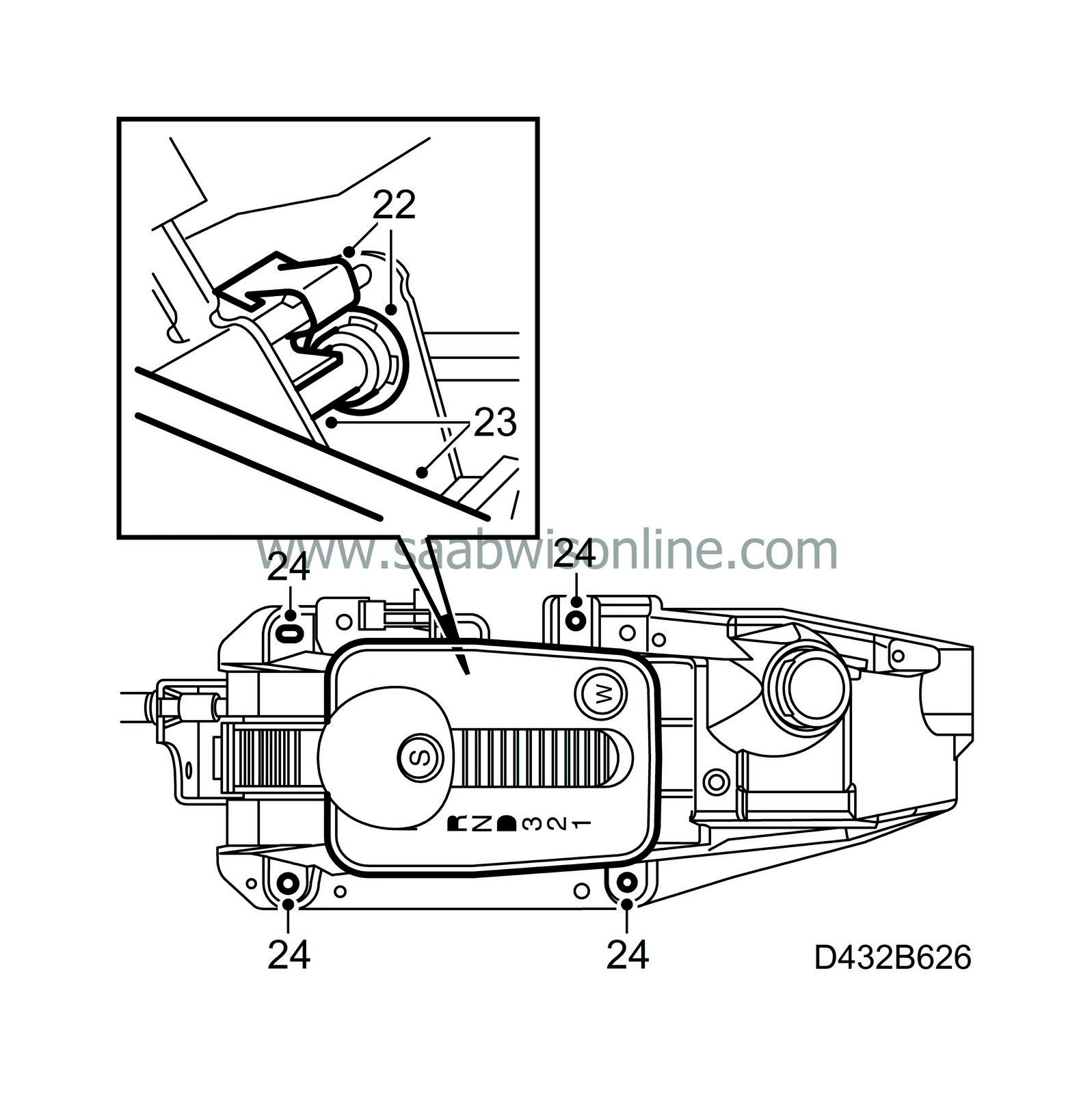
Remove the E-circlip and anti-rattle clip.
|
|
23.
|
Drive out the pin while removing the end of the cable from the ball.
|
|
24.
|
Remove the screws securing the selector lever housing.
|
|
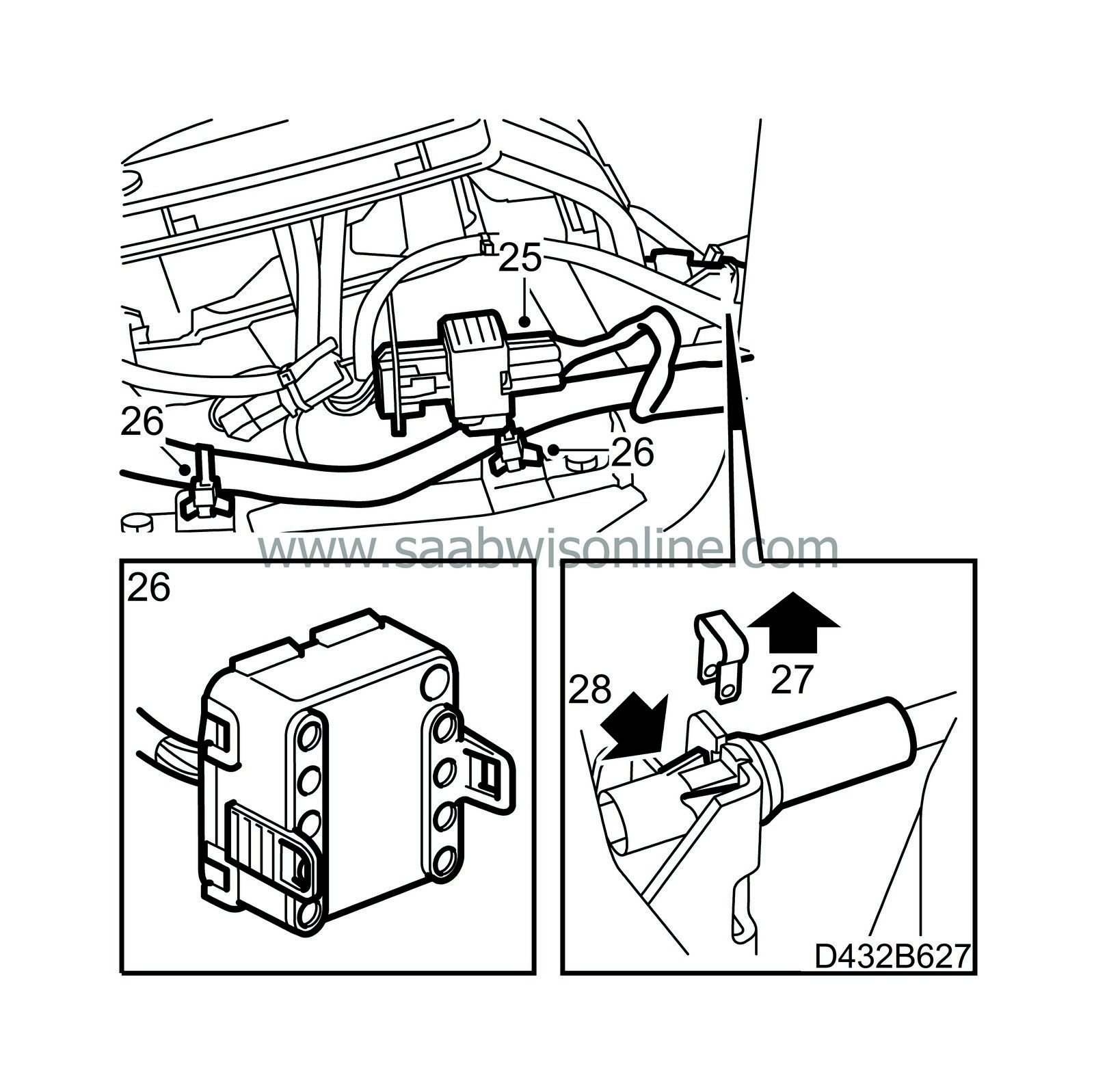
25.
|
Unplug the selector lever housing's connector.
|
|
26.
|
Lift up the selector lever housing, undo 2 cable ties securing the wiring harness to the ignition switch and the airbag control module. Unplug the electric connection from the ignition switch.
|
|
27.
|
Remove the clamp located beside the locking catches.
|
|
28.
|
Carefully press the catches securing the cable ferrule towards each other and remove the cable from the bracket.
|
|
29.
|
Lift out the selector lever housing.
|
Important
|
|
When working on a dismantled selector lever housing, the selector lever casing should be protected with foam rubber or the like.
|
|
|
|
|
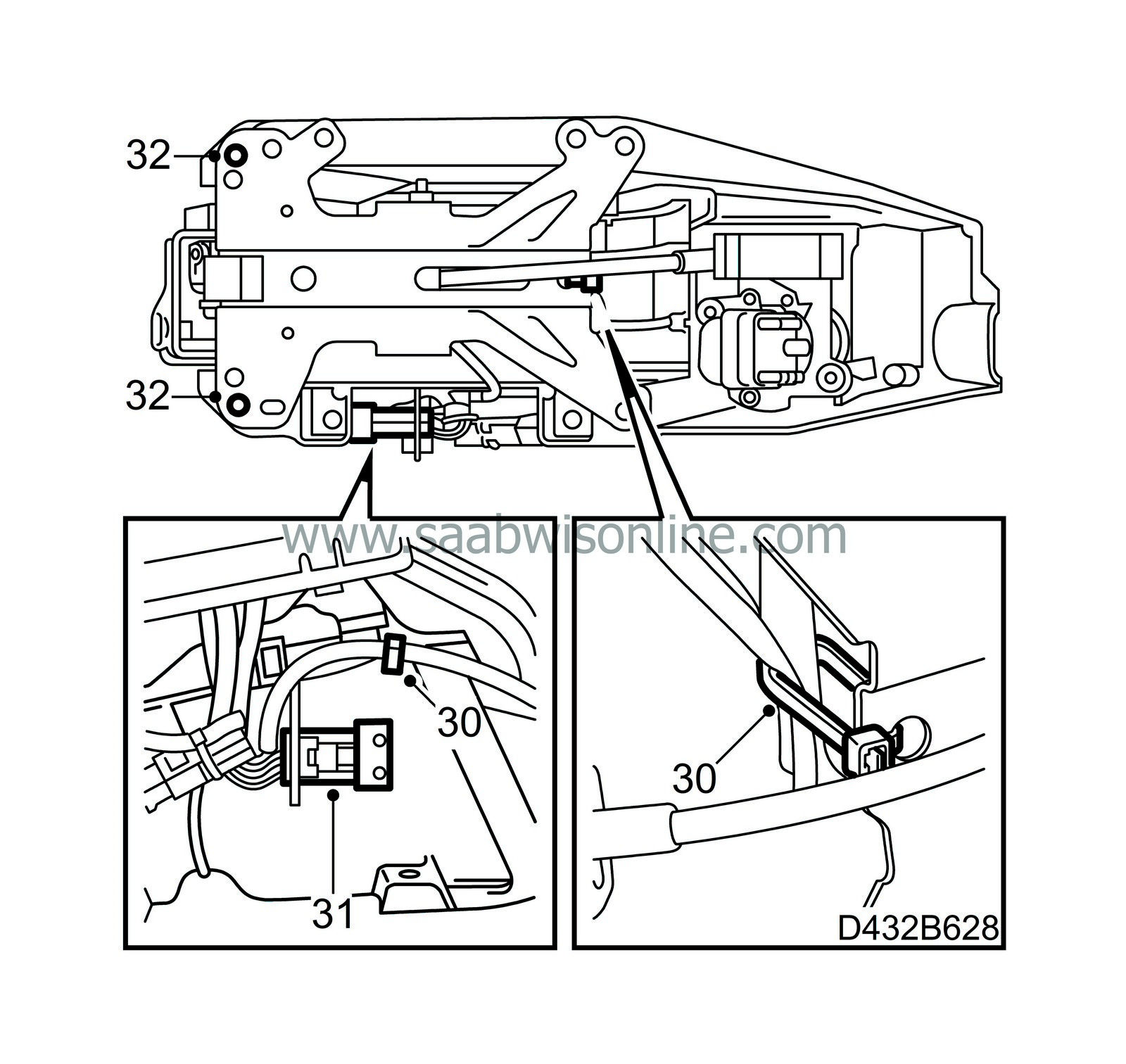
30.
|
Cut the cable ties.
|
|
31.
|
Remove the pins for the electromagnet from the connector: pins 5 and 6 in the 6-pin and pin 2 in the 2-pin connectors. Use tool 85 80 151.
|
Note
|
|
Note the position of the 3 pins in the connector.
|
|
|
32.
|
Drill out the rivets with a 3 mm drill.
|
|
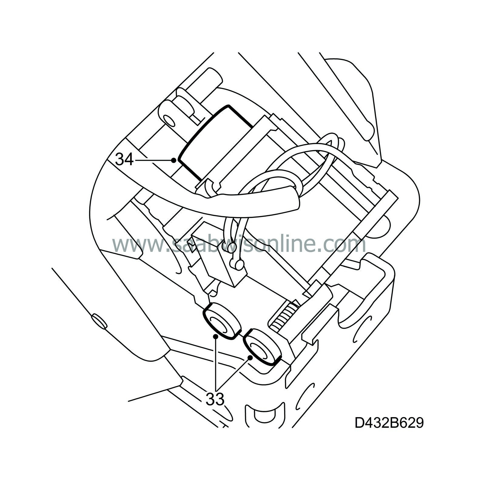
33.
|
Separate the upper and lower parts of the selector lever housing and remove the screws by the electromagnet.
|
|
34.
|
Undo the lever at the top of the electromagnet and remove the electromagnet.
|
|
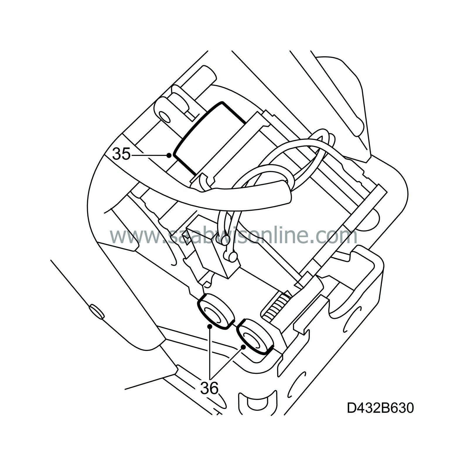
35.
|
Fit a new electromagnet to the lever.
|
|
36.
|
Fit the 2 electromagnet screws.
|
|
37.
|
Fit the two parts of the selector lever housing together.
|
|
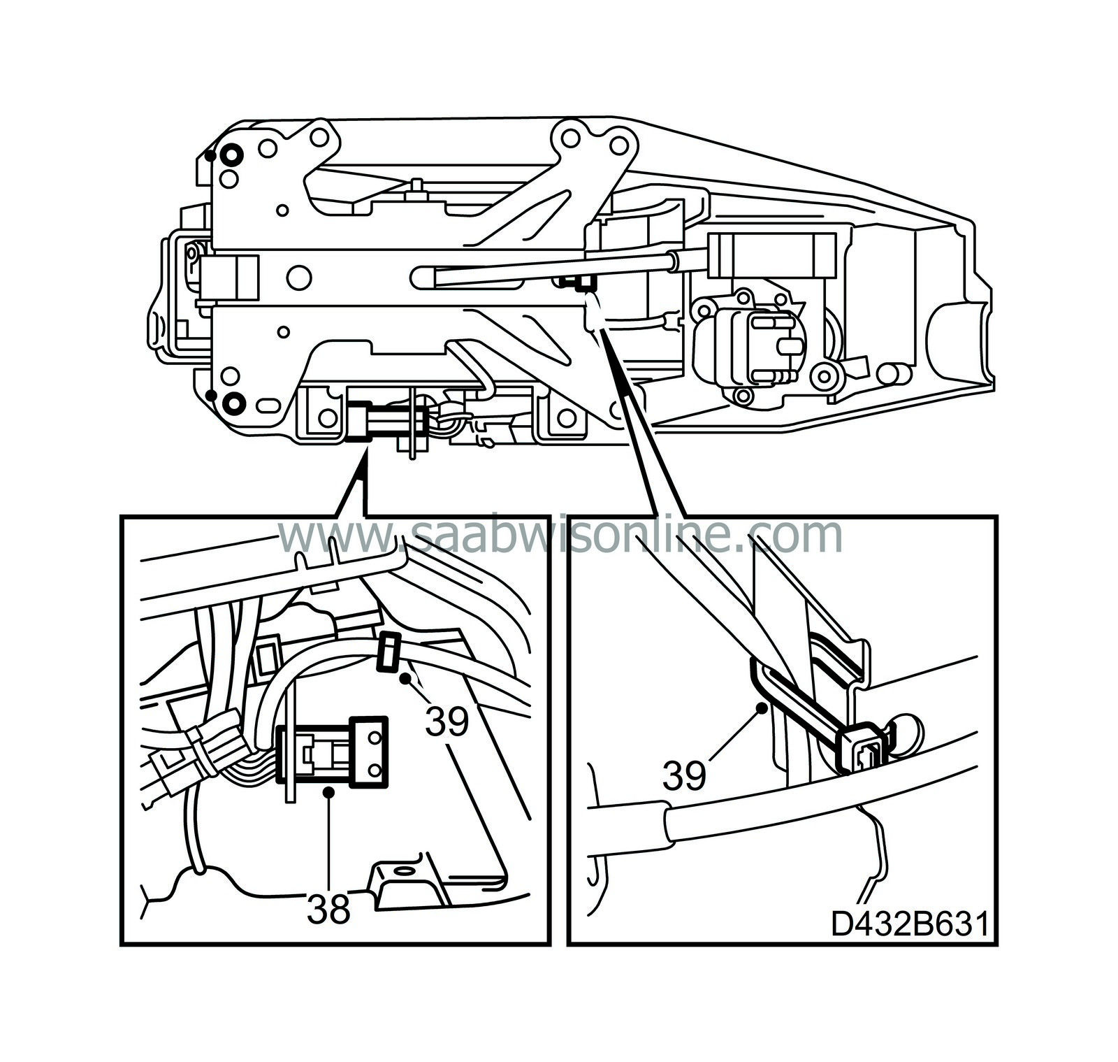
38.
|
Connect the electromagnet leads.
|
|
39.
|
Secure the leads with a cable tie.
|
|
40.
|
Fit the selector lever housing in place.
|
|
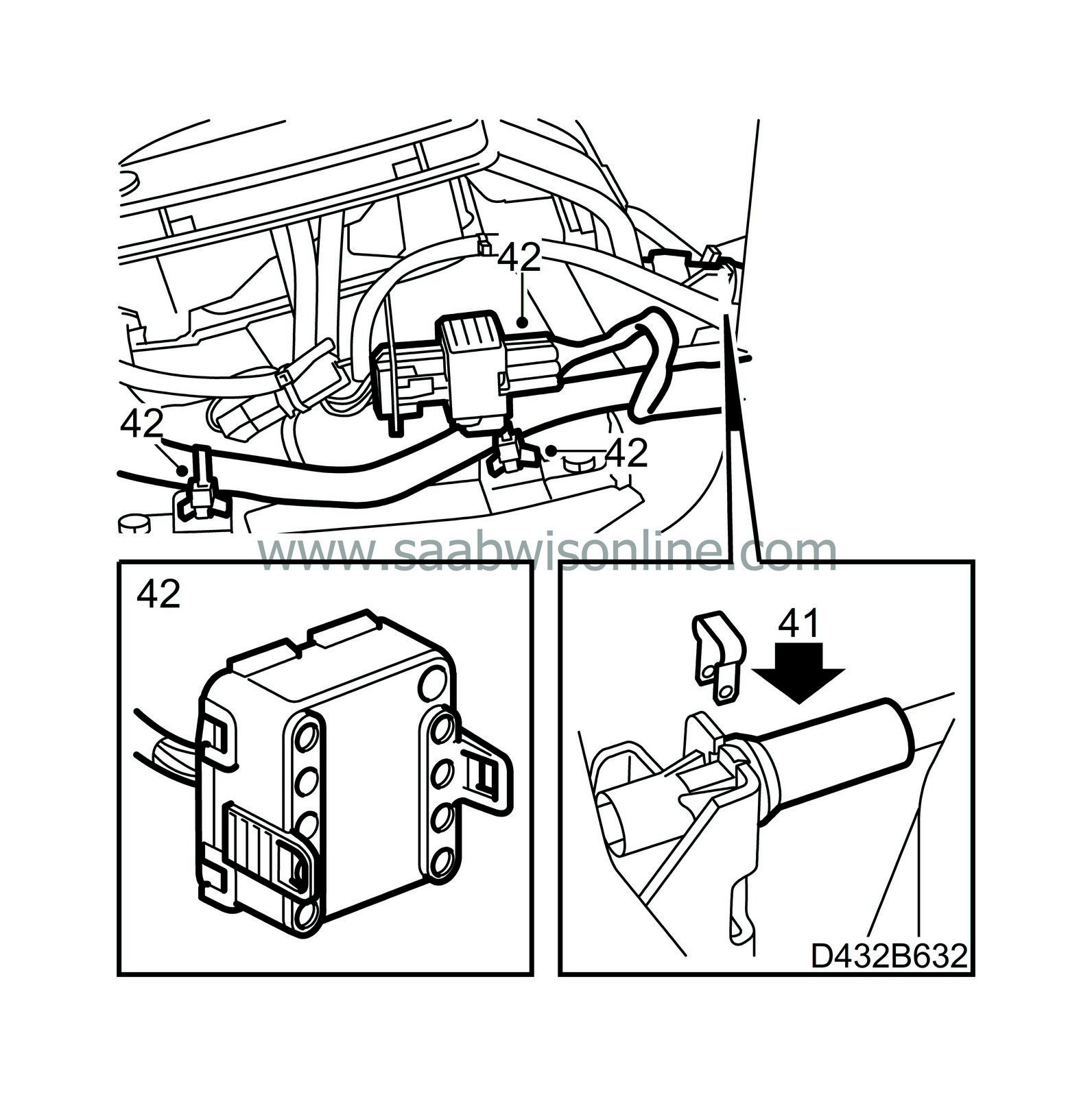
41.
|
Connect the cable to the selector lever housing and fit the clamp.
|
|
42.
|
Plug in the electric connection to the ignition switch and selector lever housing. Refit the 2 wiring harness cable ties.
|
|
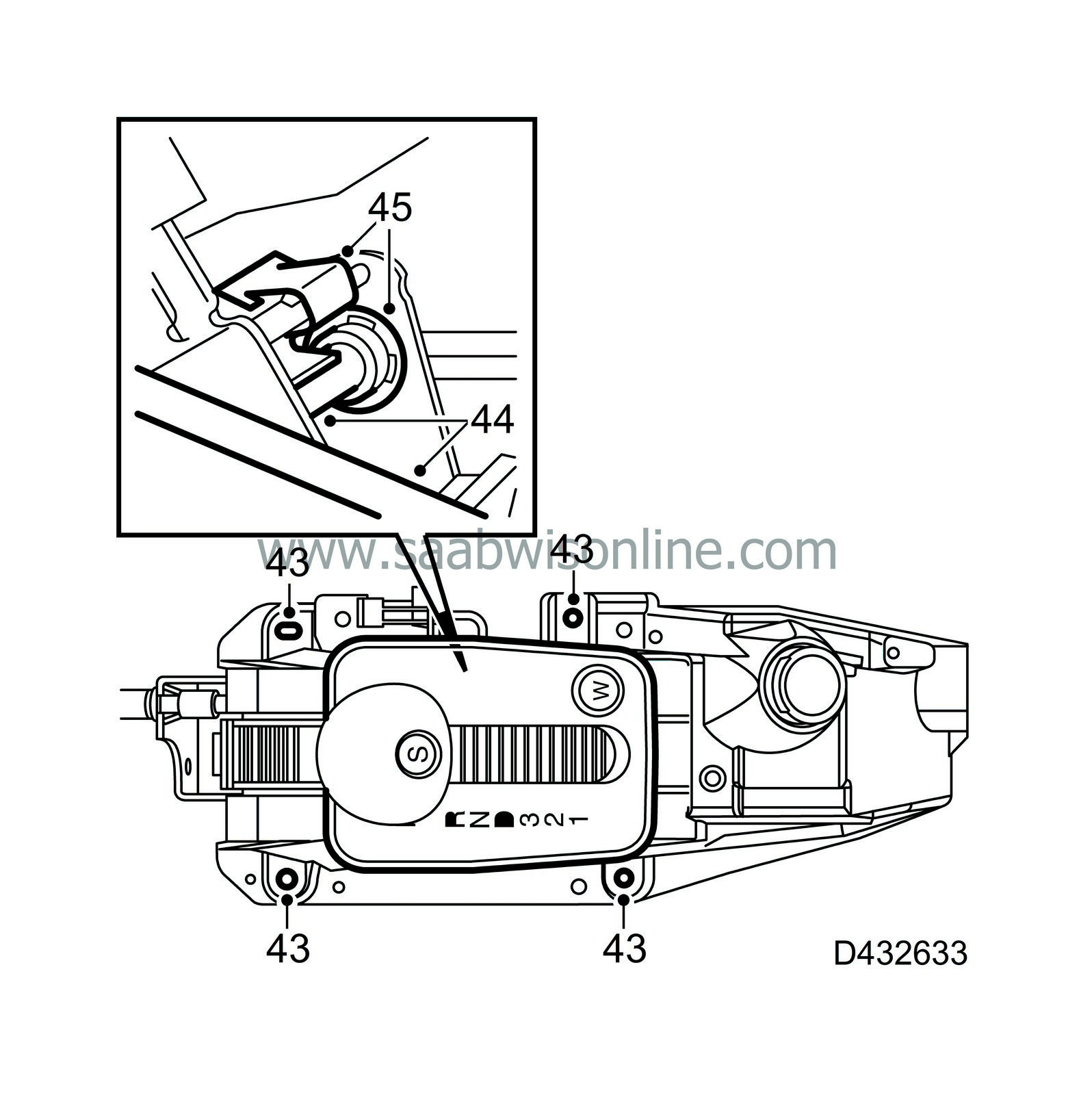
43.
|
Tighten the selector lever housing and connect the air duct.
|
|
44.
|
Tap in the pin at the same time as the ball enters the end of the cable.
|
|
45.
|
Fit the E-circlip and anti-rattle clip.
|
|
46.
|
Put the centre console in place over the selector lever housing.
|
|
47.
|
Fit the expanding rivets securing the console to the dashboard (press first in the rivet and then the centre pin). Do not screw the rear retaining screw tight as it is also used to secure the floor console.
|
|
48.
|
Plug in all the connectors in the centre console.
Orange connector - right-hand seat heating
Yellow connector - left-hand seat heating
|
|
49.
|
Cars with ACC:
Plug in the ACC module connector and press in the module.
|
|
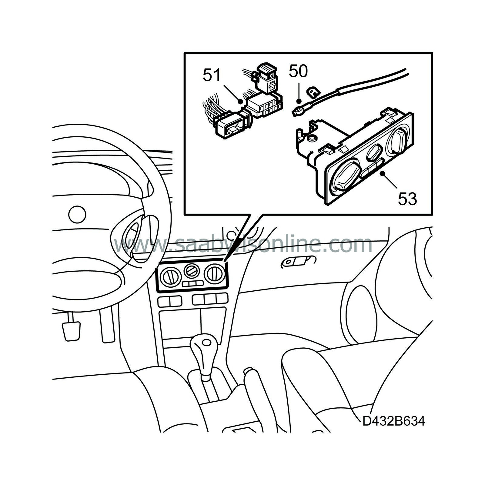
50.
|
Cars without ACC:
Attach the cable to the heating control on the control panel. The cable is fastened with an eyebolt and locked with a locking washer.
|
|
51.
|
Cars without ACC:
Plug in the connector to the control panel.
|
|
52.
|
Cars without ACC:
Attach the air distribution shaft to the air distribution control.
|
|
53.
|
Cars without ACC:
Fit the heater control panel.
|
|
54.
|
Fit the rim.
|
|
55.
|
Fit the right and left-hand side pieces by sliding the guide of each piece into the centre console and fitting the retaining screws.
|
|
56.
|
Fit the floor console over the handbrake. Do not press it home.
|
|
57.
|
Insert the connectors for the window lift module and interior lighting (convertible) through the hole for each unit.
|
|
58.
|
Plug in the window lift module connectors and fit the module.
|
|
59.
|
Convertible
Plug in the interior lighting connector and fit the switch.
|
|
60.
|
Tighten the floor console retaining screws and nuts.
|
|
61.
|
Put the rear cover in place, making sure the air duct connects correctly to the air distributor.
|
|
63.
|
Fit the ashtray/cover.
|
|
64.
|
Fit the ignition switch cover.
|
|
65.
|
Fit the antenna unit.
|
|
66.
|
Adjust the position of the cable.
|
|
Marking the modification identity plate
|
On completion of the repair, box A4 of the modification identity plate should be marked. Mark it with a “7” if the repair was carried out by the importer or with an “8” if done by a dealer.
|
Warranty/Time information
|
See separate information.


