PRE-RELEASE
System overview
| System overview |
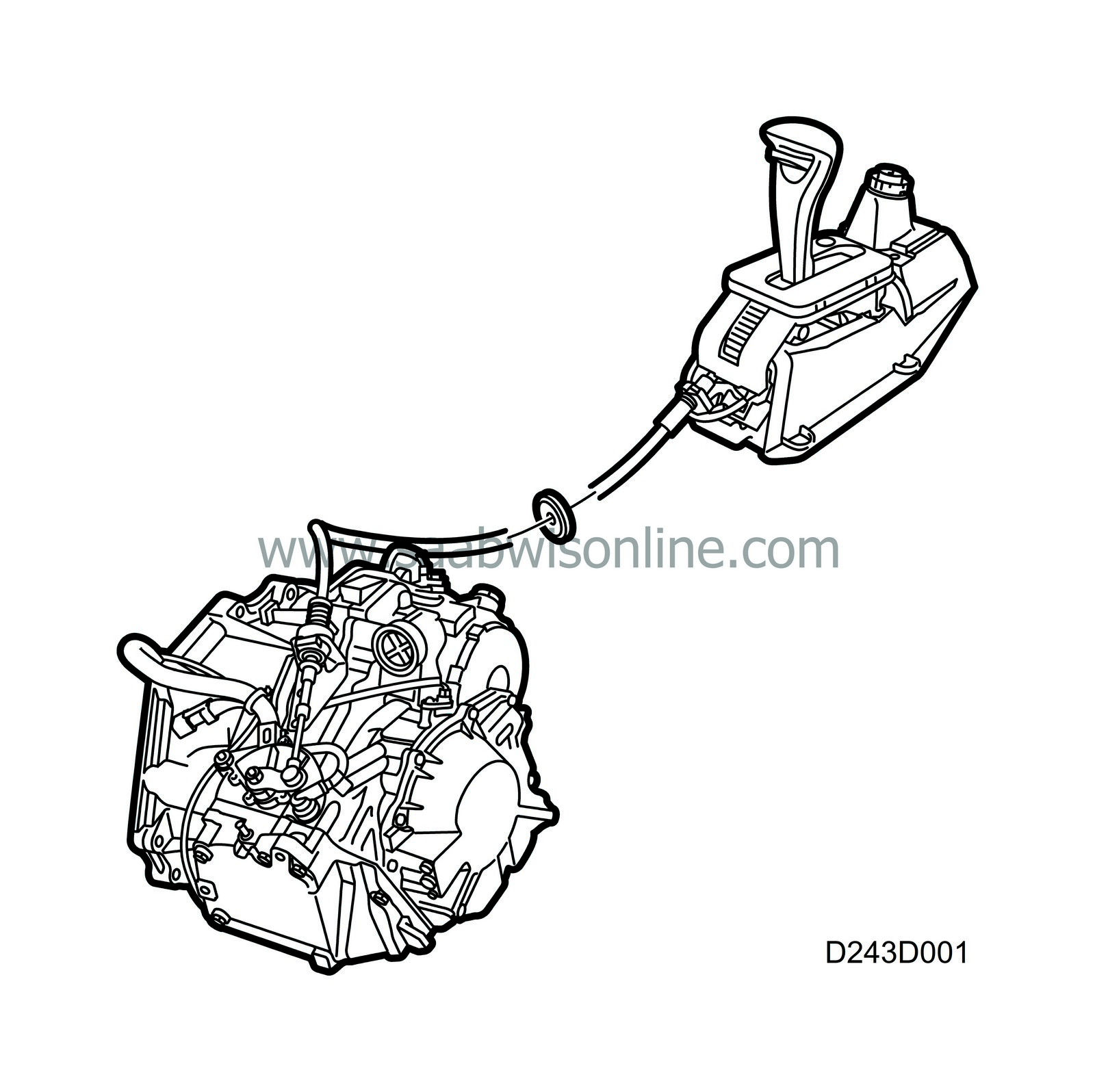
The selector lever position sensor is connected to the manual shifting valve in the valve housing, which is also actuated by the selector lever.
| The following shift-lock functions are provided in the selector lever housing: |
Shift-lock (certain markets)
Shift-lock means that the brake pedal must be depressed and the ignition key turned to the ON position before the gear selector can be moved from P-position.Anti-theft/Starter motor interlock function
The ignition key must be in the ignition and turned to the OFF position before the gear selector can be moved from the P-position.Gear lock function
The release button on the gear selector lever must be depressed before the lever can be moved between the various positions (PRND321).Shift-lock function (certain markets)
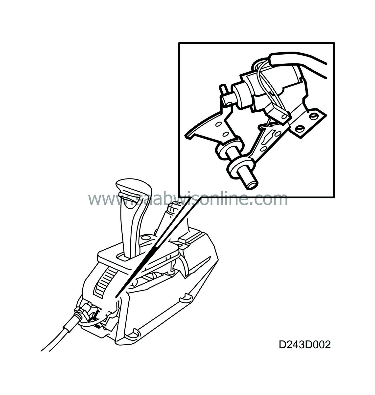
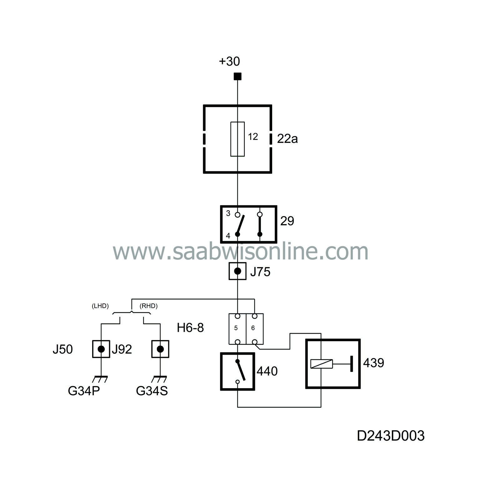
When the shift-lock function is operative, the brake pedal must be depressed and the ignition switch turned to the ON position before the selector lever can be moved out of position P. This function is accomplished by means of a microswitch and a solenoid.The microswitch is actuated by a cam on the selector lever and is closed only when the selector lever is in position P.
The solenoid blocks the selector lever's segment mechanically if it is not activated.
With the ignition key turned to position ON and the brake pedal depressed (brake light switch closed), the solenoid is supplied with current via the microswitch (gear selector in position P). The solenoid is then activated and the block on the selector lever segment is released. The solenoid is grounded to grounding point G42, whereby the gear selector lever can be moved from position P.

To disable the SHIFT-LOCK function in the event of power loss, proceed as follows:
| 1. |
Turn the ignition switch to the OFF position.
|
|
| 2. |
Depress the oblong button at the side of the selector lever to release the SHIFT-LOCK function.
|
|
Anti-theft/Starter motor interlock function
When this function is operative, the ignition key must be inserted in the ignition switch and turned at least to the OFF position before it will be possible to move the selector lever out of position P.The interlock function consists of the ignition switch, a locking pin and a mechanical cable connecting these components.
When the selector lever is in position P and the ignition switch is in the OFF position, the cable pulls the locking pin into a tooth space to lock the selector lever in position P.
Selector lever position catch
A release button on the selector lever must be activated before it will be possible to move the lever between the different positions (PRND321).This function consists of a catch, a locking pin and a rod which connects these components. The locking pin blocks the lever in the different positions and when the catch is activated the selector lever is released from the locking segment and can then be moved to the desired position.


