PRE-RELEASE
SRS control module
| SRS control module |
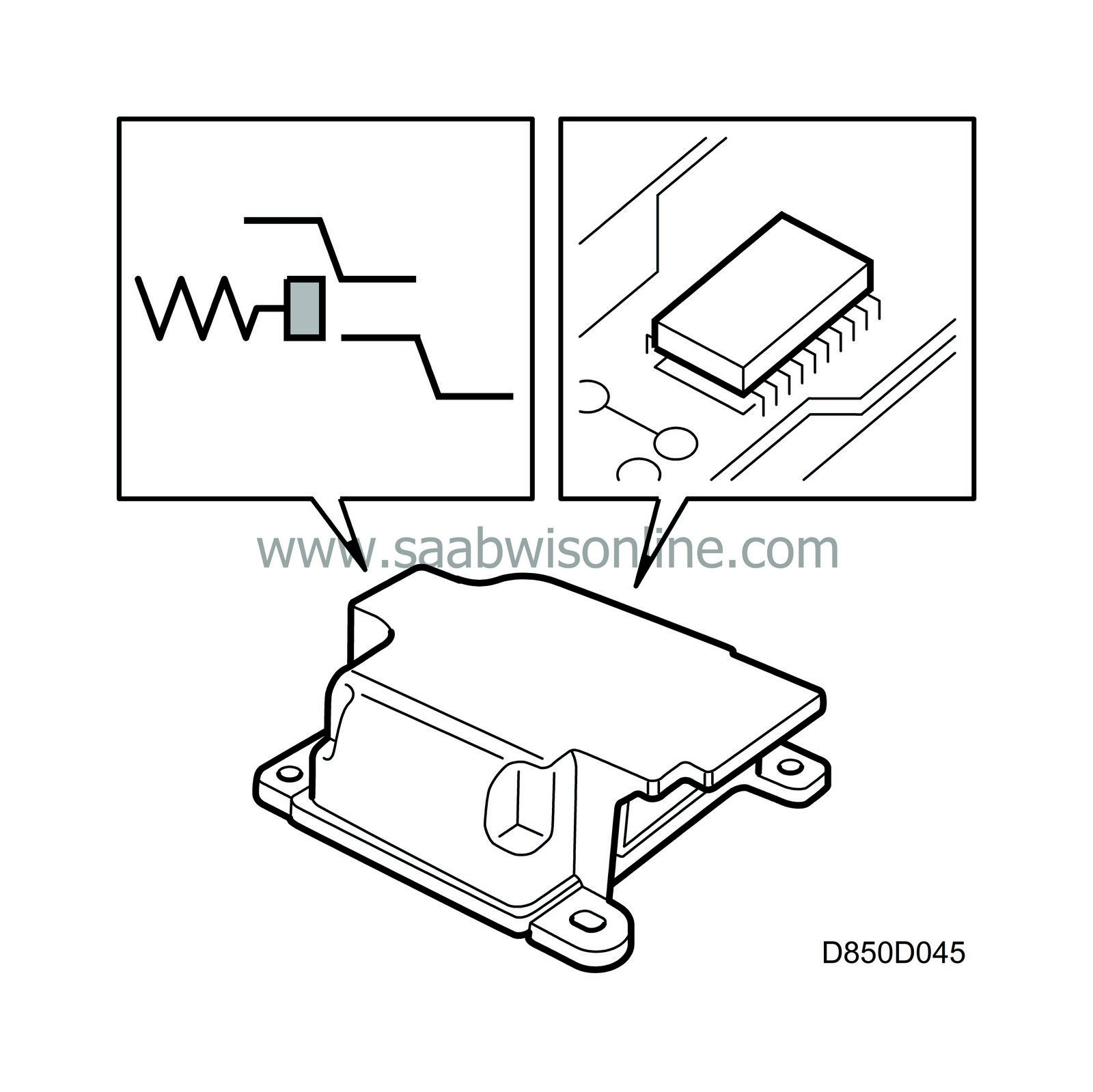
The control module incorporates an electromechanical safety sensor of magnetic reed type, a microprocessor, three backup power sources, one voltage converter and an accelerometer.
The task of the safety sensor is to detonate the front airbags and the seat-belt tensioners during extreme retardation. This is achieved when a spring-loaded magnet reaches the reed element and closes the detonation circuit.
As this sensor is coupled in series in the detonator circuits for the front airbags, it is not sufficient for only the microprocessor to activate the front airbags. To activate the front airbags and the seat belt tensioners, two basic requirements must be fulfilled:
| 1. |
The safety sensor must be closed.
|
|
| 2. |
The microprocessor must have found that the necessary conditions prevail for activation of the front airbags.
|
|
An acceleration sensor which senses acceleration and retardation of the car in its direction of travel is provided to enable the control module to recognize a collision situation. When the car's retardation exceeds a certain limit, the processor starts to process the signal from the acceleration sensor with greater precision.
If retardation continues to increase and exceeds the values defined as a collision, the processor will send pulses to the relevant detonator.
The seat belt tensioners and the front airbags are activated simultaneously and only in the event of a head-on collision, retardation.
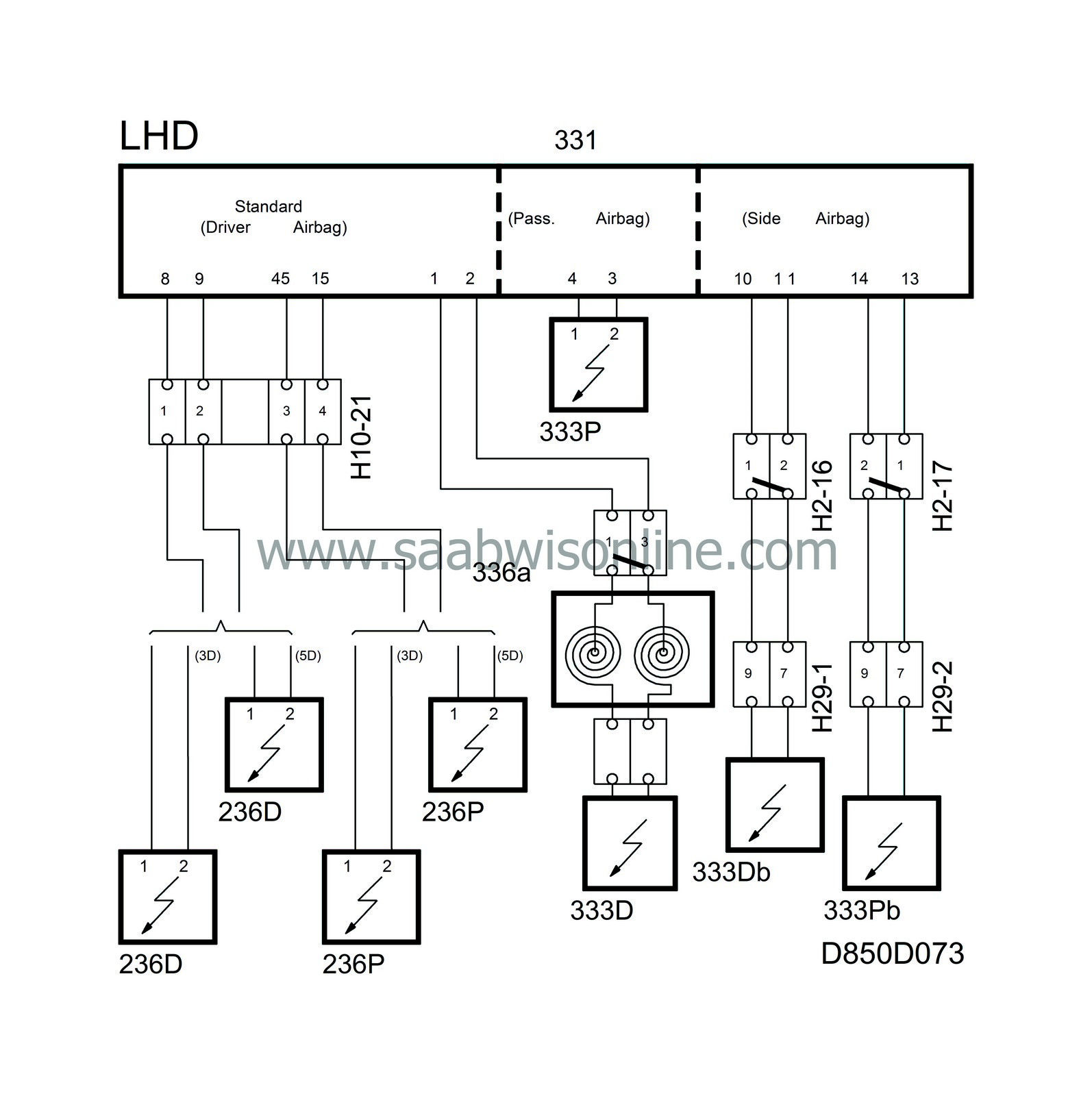
The control module has the capacity to activate six different detonation circuits:
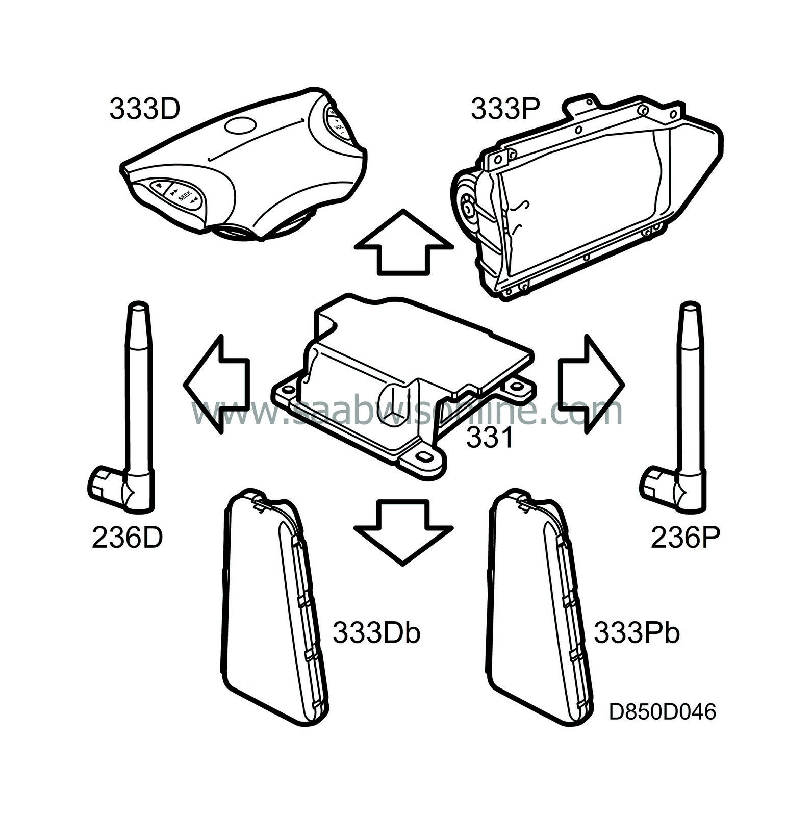
| • |
Airbag, driver
|
|
| • |
Airbag, passenger
|
|
| • |
Seat-belt tensioner, left (LH)
|
|
| • |
Seat-belt tensioner, right (RH)
|
|
| • |
Side airbag, driver
|
|
| • |
Side airbag, passenger
|
|
The activation times in a collision may be different for the different circuits.
In a side collision, the side impact sensor registers the pressure change in the front doors. If the pressure build-up per unit time coincides with the limits that have been defined as constituting a collision, crash information is supplied to the control module which then activates the side airbag on the side of the car affected by the collision.
| Backup power |
The control module has three backup power sources. Two of them enable the front airbags to be activated for a minimum of 150 milliseconds after the regular power supply has failed and the third backup power source keeps the processor going for 150 milliseconds after the regular power supply has failed.
| On-board diagnostics |
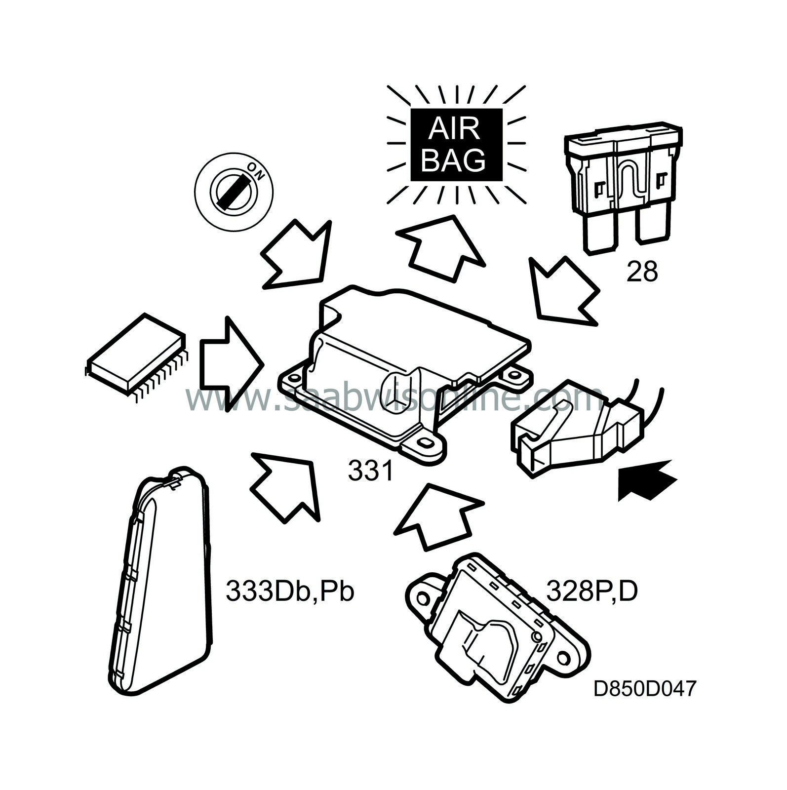
When the ignition switch is in the ON position and the system is supplied with current, the control module carries out initial self-diagnosis for a maximum of 10 seconds. As a safety measure, the airbags cannot be activated during this period.
The electric detonators and the wiring, power supply, airbag warning lamp, microprocessor and side impact sensors are all checked during this self-diagnosis.
The airbag warning lamp lights up during the first test when the current is turned on for 3-4 seconds to check the lamp. Self-diagnosis then continues for as long as the ignition switch remains in the ON position.
There are 41 diagnostic trouble codes covering all sensors, wiring harnesses, airbags, seat belt tensioners and internal control module faults.
The control module can measure shorting to earth and B+ and also excessive and insufficient resistance in all detonation circuits. In the event of a system fault the airbag warning lamp will come on.
The control module monitors the diagnostic trouble code conditions at different intervals, depending on the diagnostic trouble code concerned.
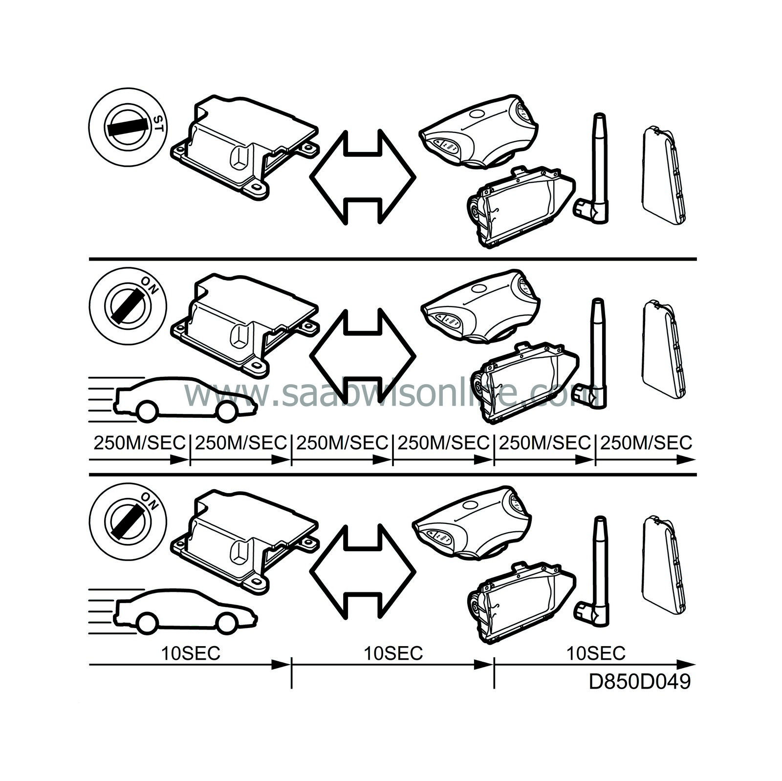
These are the different types of monitoring:
|
On starting
|
Within the first 10 seconds of turning the ignition switch to the ON position
|
|
Continuously
|
Every 250 milliseconds under normal operating conditions
|
|
Periodically
|
A 10-second cycle
|
|
Non-continuous monitoring
|
Event-controlled, e.g. reception of a fault message from a side impact sensor
|
After having activated the front airbags once, the control module is expended. The control module can be reused max twice after activating the seat-belt tensioners and/or side airbags, i.e. the side airbags and/or seat-belt tensioners can be activated three times. A diagnostic trouble code will be generated each time an airbag or belt tensioner is activated. See Fault diagnosis, diagnostic trouble codes.
Diagnostic trouble code B1615 is generated when the control module is spent, see also B2880, B2885 . The number of activations can be read from the Read value menu.
Storage of diagnostic trouble codes
Up to 8 diagnostic trouble codes can be stored in the SRS control module's memory, 5 of them prioritized places reserved for: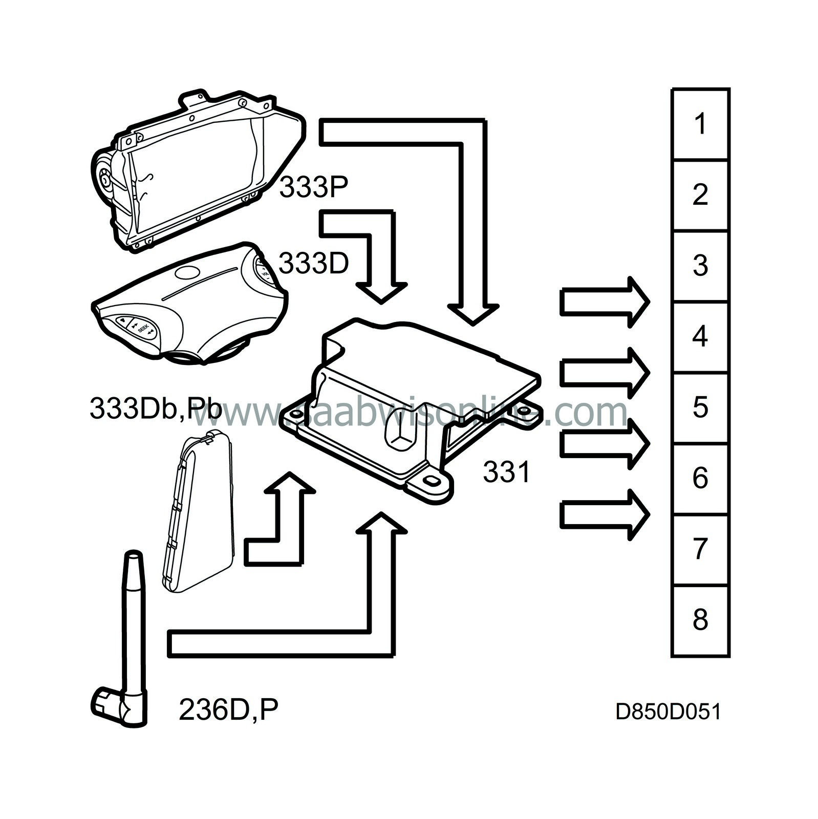
| • |
driver airbag activated
|
|
| • |
passenger airbag activated
|
|
| • |
seat-belt tensioner activated
|
|
| • |
driver side-airbag activated
|
|
| • |
passenger side-airbag activated.
|
|
If no prioritized diagnostic trouble code has been generated, the eight places are available for normal diagnostic trouble codes. If any of the prioritized trouble codes occurs after “non-prioritized” codes have been generated, these codes will overwrite the last 5 “non-prioritized” codes.
| Programming the SRS control module |
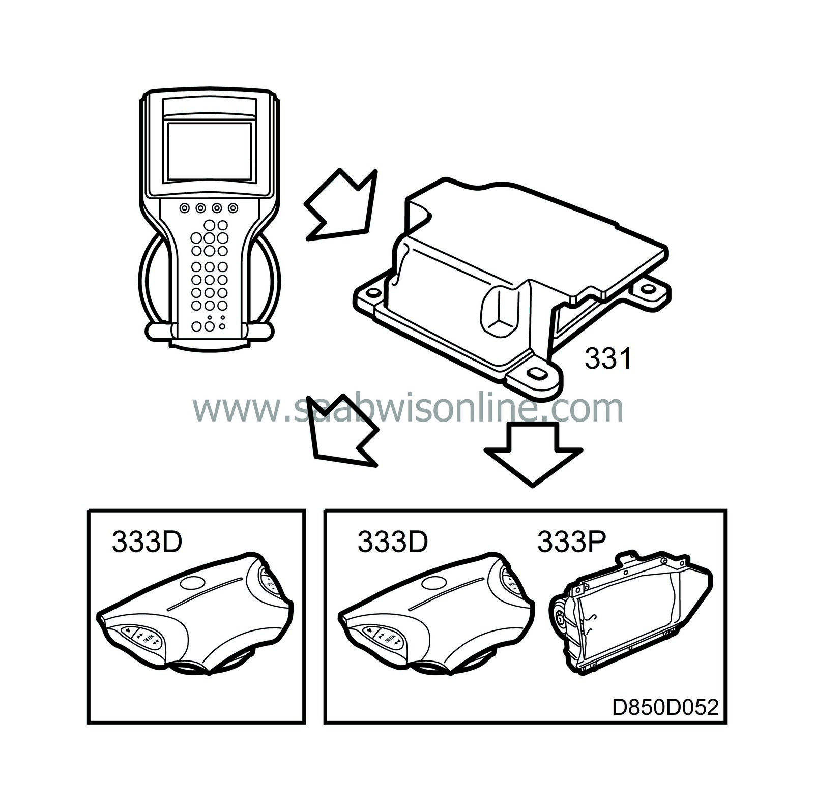
As delivered from the manufacturer, the SRS control module is not functional until it has been programmed for the car in which it has been fitted. In the programming procedure the functions of the control module are compared with the hardware that is in place in the car.
The control module checks whether the requested programming is compatible with the components that it detects electrically in the car, until the ignition is switched off. If the detected components are not compatible with the desired programming, a diagnostic trouble code will be generated. In this way it is possible to find out why the car's equipment and the desired control module programming are incompatible.
When changing the SRS control module, the replacement must be programmed for the car in which it is to be fitted. This is done with the diagnostic tool.
After programming has been successfully completed, the parameters will be locked in the control module and cannot be changed.
| Power supply |
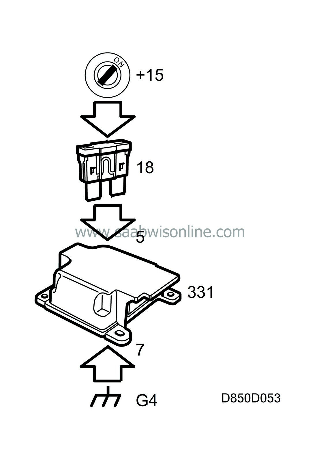
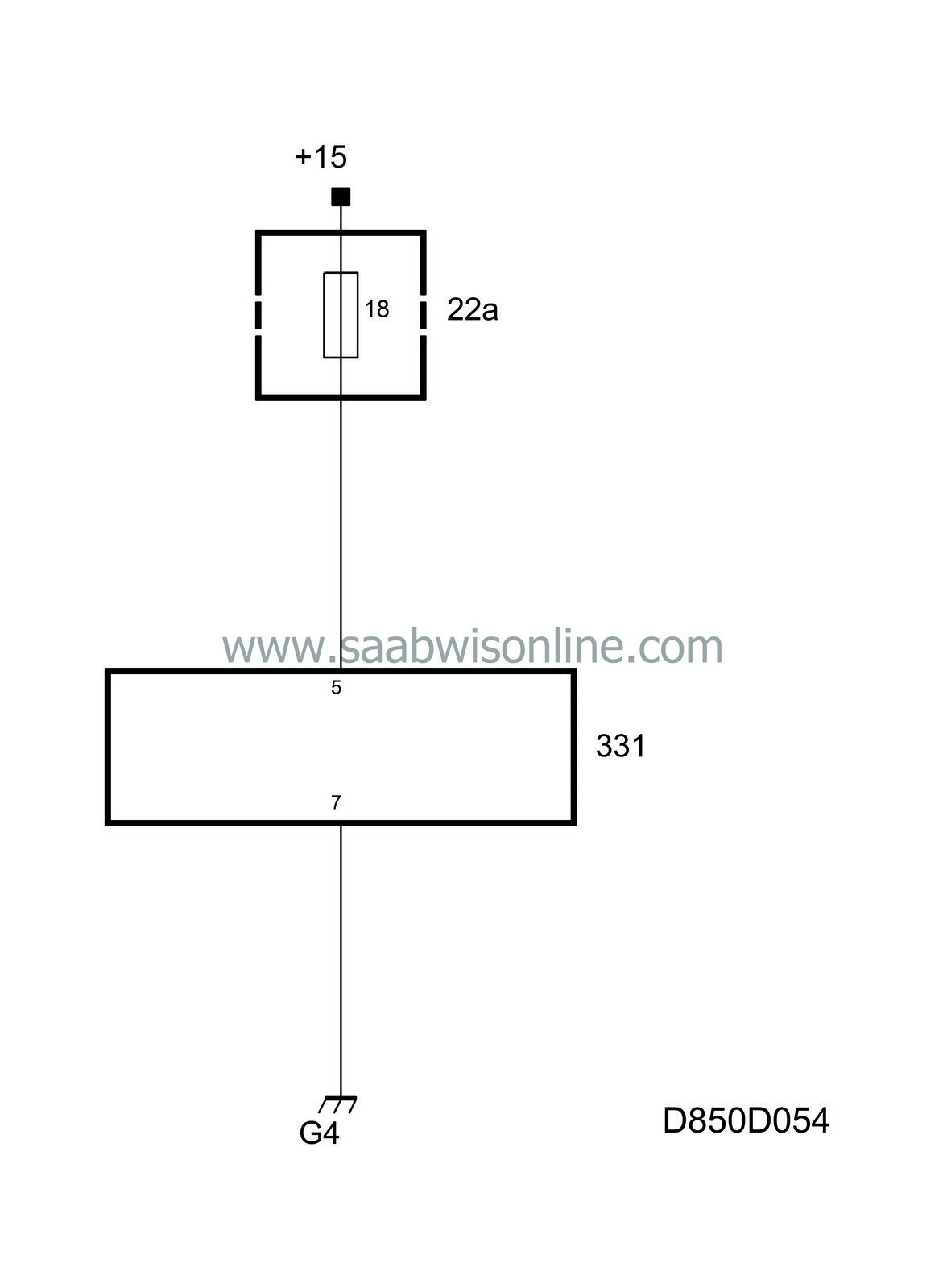
With the ignition switch in the ON position, current (+15) is supplied to pin 5 of the control module via fuse 18. The control module is designed to operate on a power supply of between 9-16 V.
| Grounding |
The control module is connected to ground via pin 7 and via the three retaining screws. No ground cables from other systems must be connected to the retaining screws as this could cause malfunctioning of the SRS.
A poor ground connection will not cause a diagnostic trouble code to be generated. When connection to ground is restored after having been interrupted this corresponds to power turn-on, and the control module again runs through the on-board diagnostics program and the airbag warning lamp will light up for 3-4 seconds.
| Connector |
The control module connector has 5 short-circuiting jumpers that work in pairs when the connector is unplugged to short-circuit the leads to the two electric detonators for the front airbags, the two electric detonators for the side airbags and between the conductor for the airbag warning lamp and ground.

