Engine block B235R, B205L/R
|
|
Engine block B235R, B205L/R
|
|
Dismantling the engine block
|
|
1.
|
Unplug the cable connections of the wiring harness.
|
|
2.
|
Remove the bracket and wiring harness as one unit.
|
|
3.
|
Remove the starter motor.
|
|
5.
|
Remove the generator bracket and crankcase ventilation's oil trap complete with hoses.
|
|
6.
|
Remove the intake manifold stay.
|
|
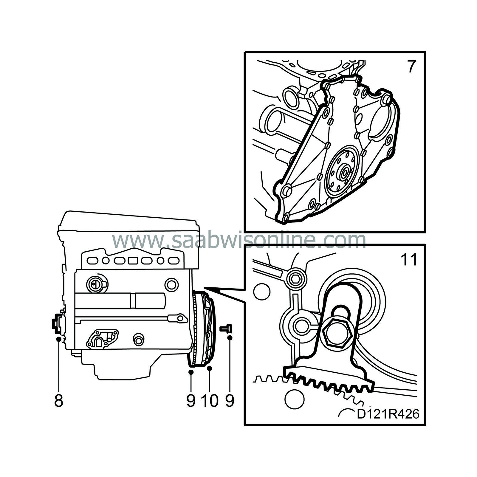
7.
|
Undo the nut on the rear engine mounting.
|
|
9.
|
Raise the power train and roll aside the trolley with subframe.
|
|
11.
|
Detach the oil filler pipe from its mounting.
|
|
12.
|
Remove the steering servo bracket with the lifting eye.
|
|
13.
|
Remove the A/C compressor bracket.
|
|
14.
|
Undo the turbocharger stay, detach the air, coolant and oil pipes and remove the turbocharger with exhaust manifold. Warm carefully if the bolts jam.
|
|
15.
|
Remove the fuel distribution pipe.
|
|
16.
|
(B235R) Remove the rear lifting eye.
|
|
17.
|
Remove the bolts retaining the intake manifold.
Lift away the pipe from the power train.
|
|
18.
|
Remove the pipe to the water pump.
|
|
19.
|
Remove the thermostat housing cover complete with thermostat.
|
|
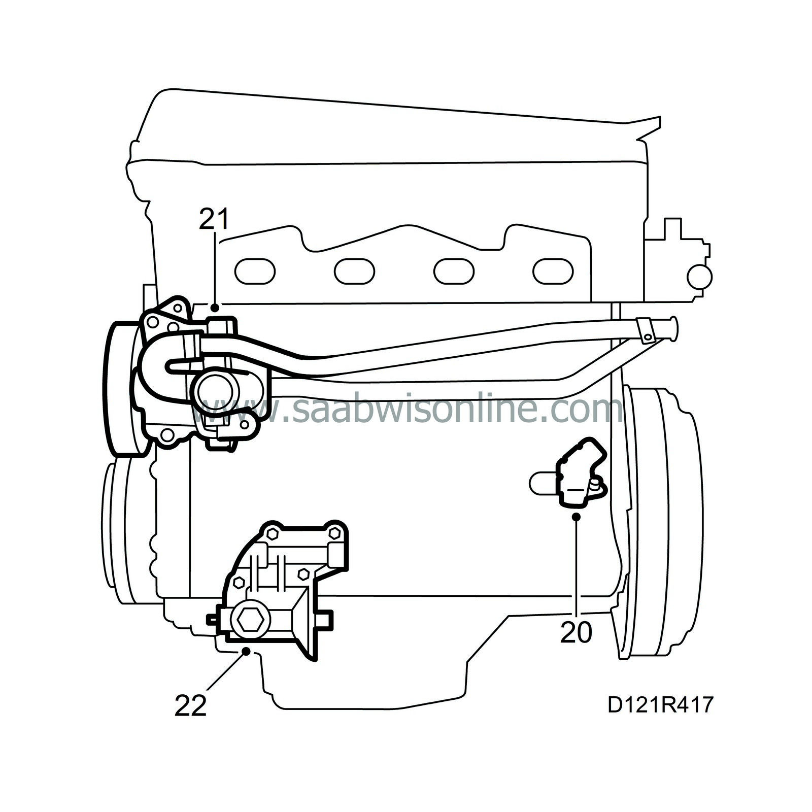
20.
|
Remove the crankshaft position sensor with protective cover.
|
|
21.
|
Remove the coolant pump complete with filler pipe and the sleeve with the O-rings.
|
|
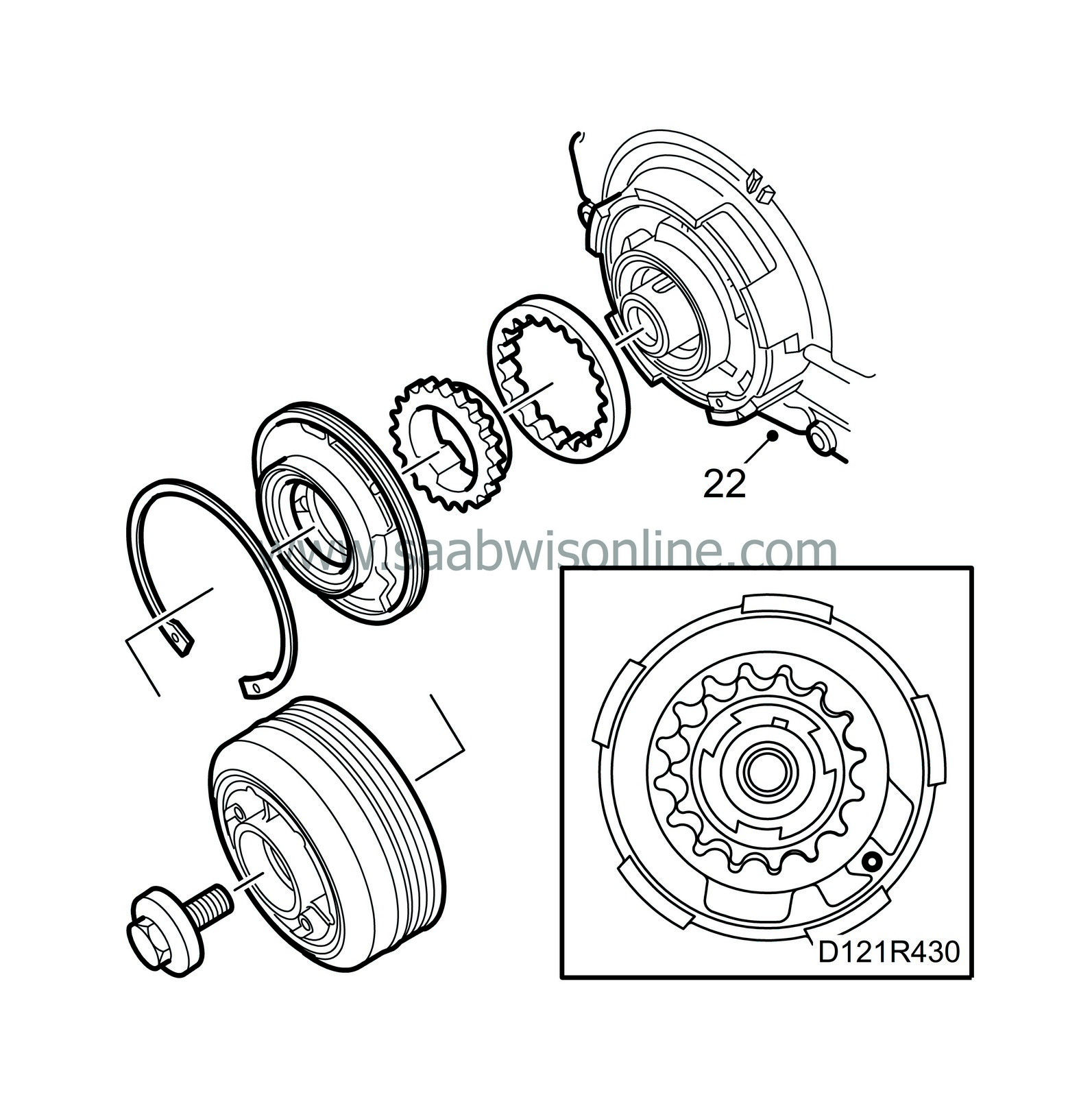
22.
|
Remove the oil filter adapter housing.
|
|
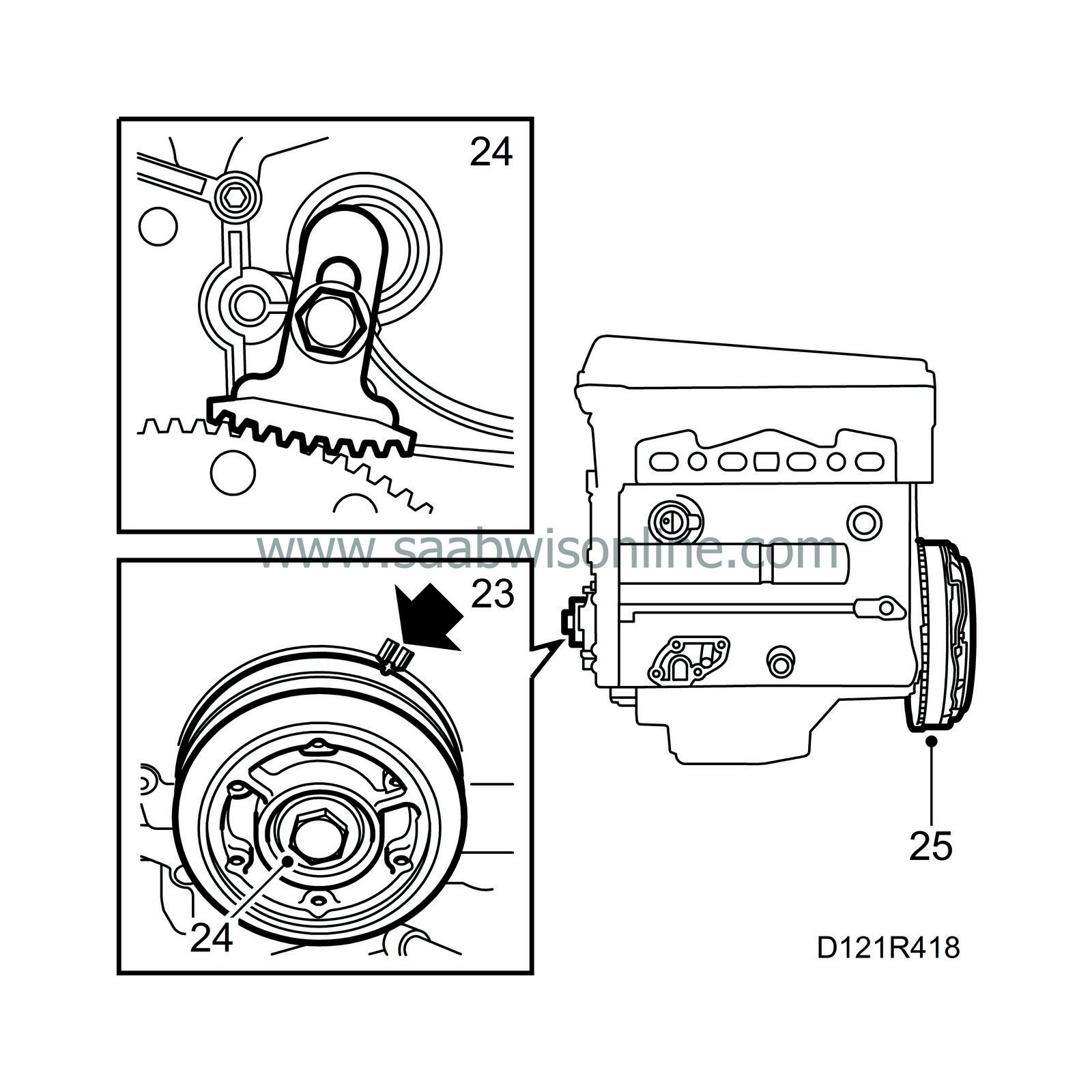
23.
|
Align the 0 mark on the crankshaft pulley with the mark on the timing cover.
|
|
25.
|
Remove the pressure plate, discs and flywheel. Remove the flywheel locking attachment.
|
|
26.
|
Remove the banjo pipe to the intake manifold.

|
|
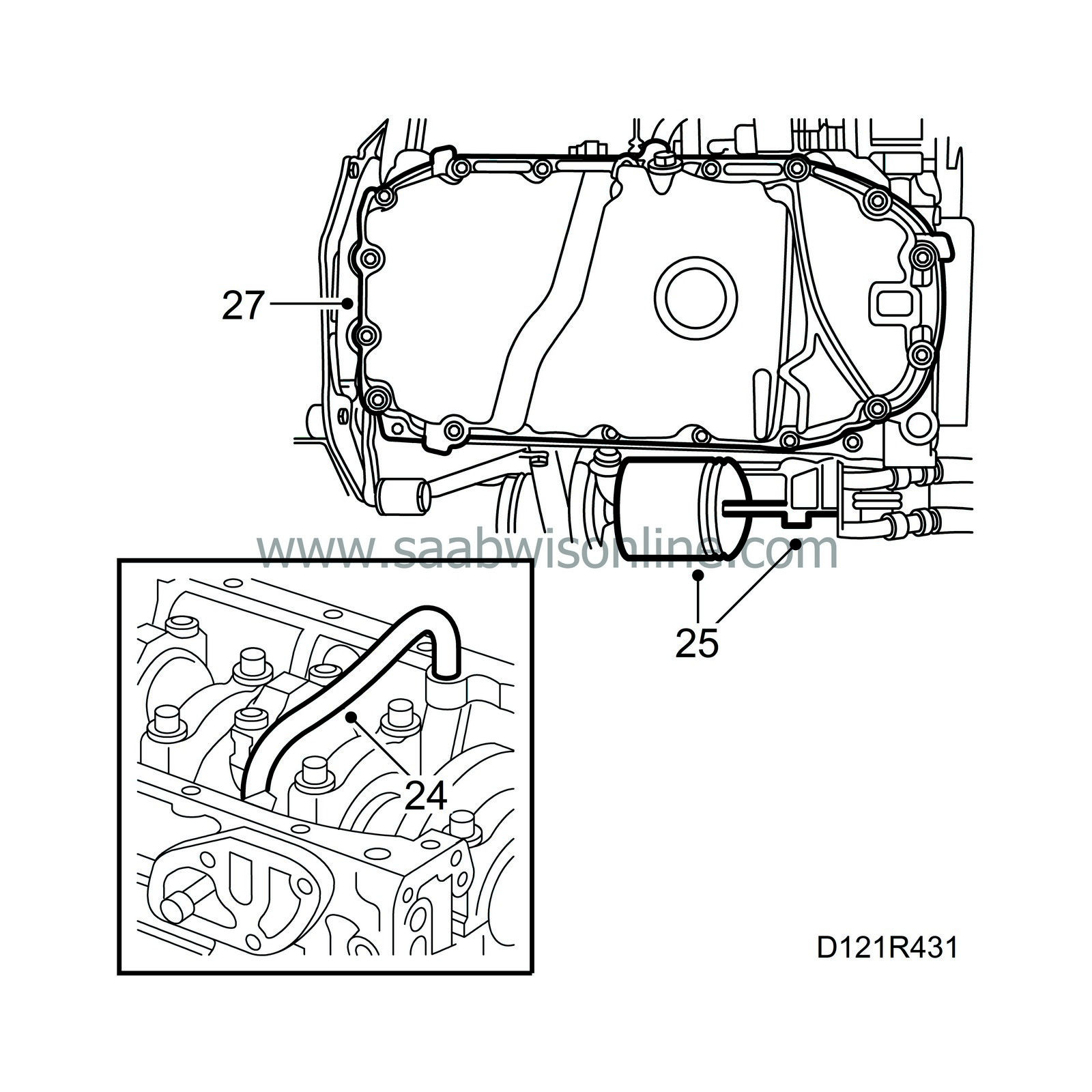
27.
|
Detach the crankcase ventilation hose.
|
|
28.
|
Remove the ignition discharge module.
|
|
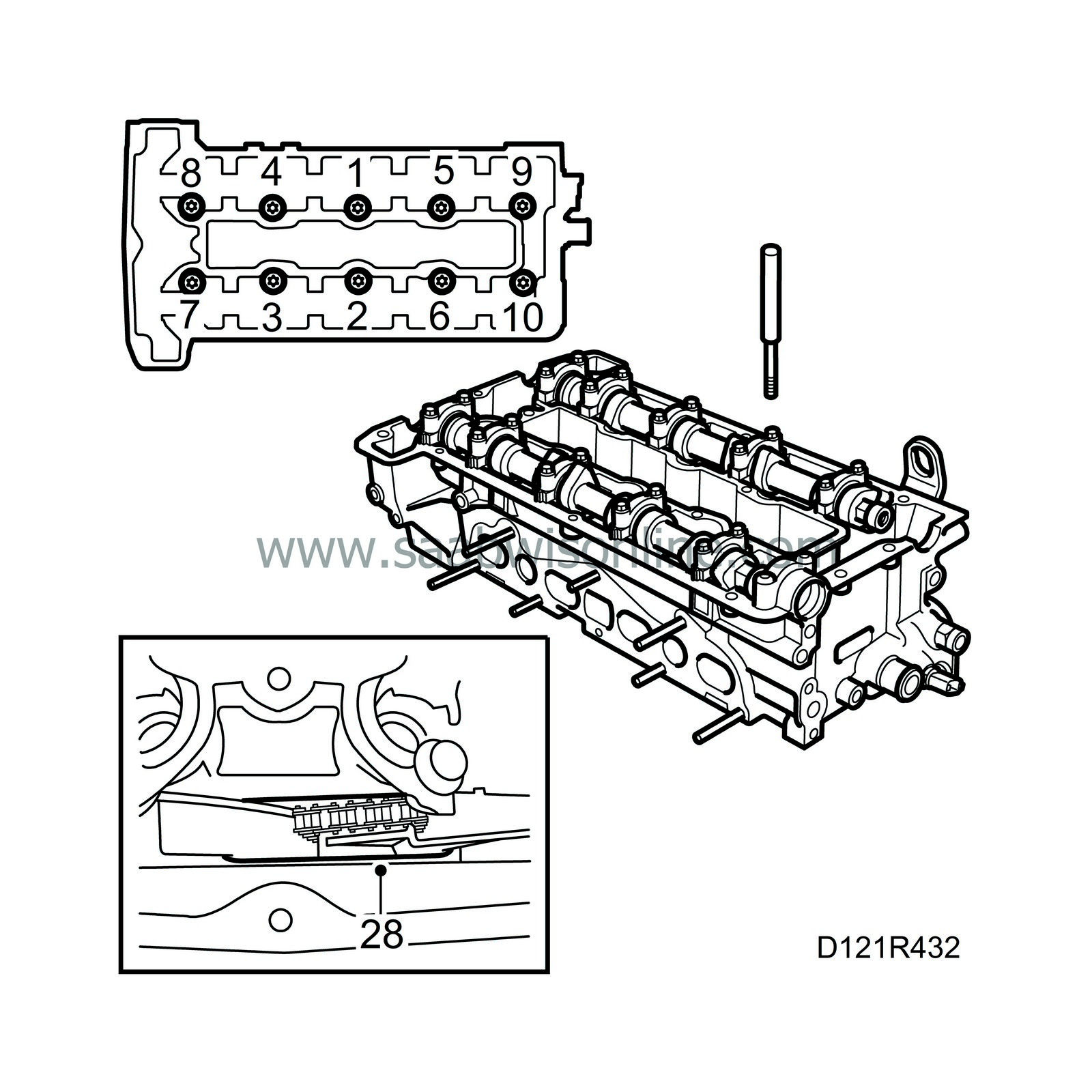
29.
|
Remove the spark plugs and remove the camshaft cover.
|
|
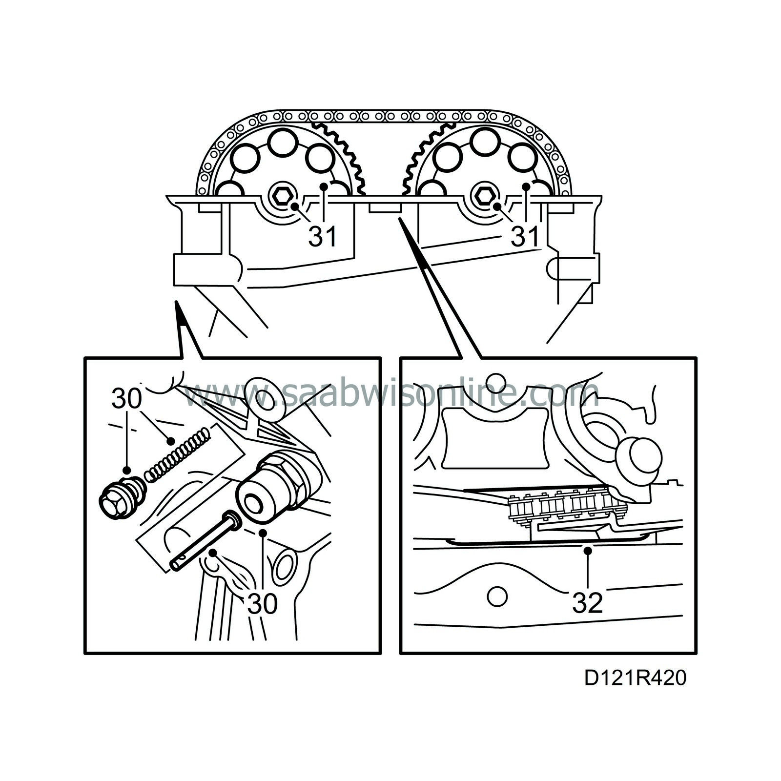
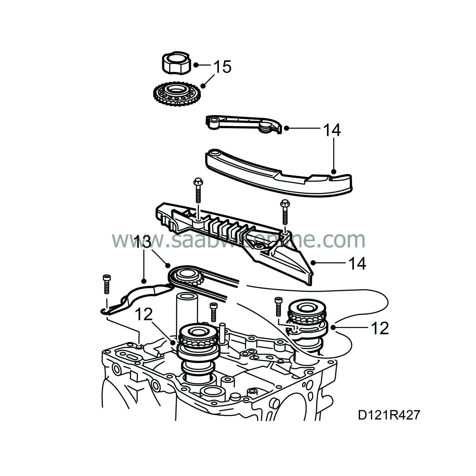
30.
|
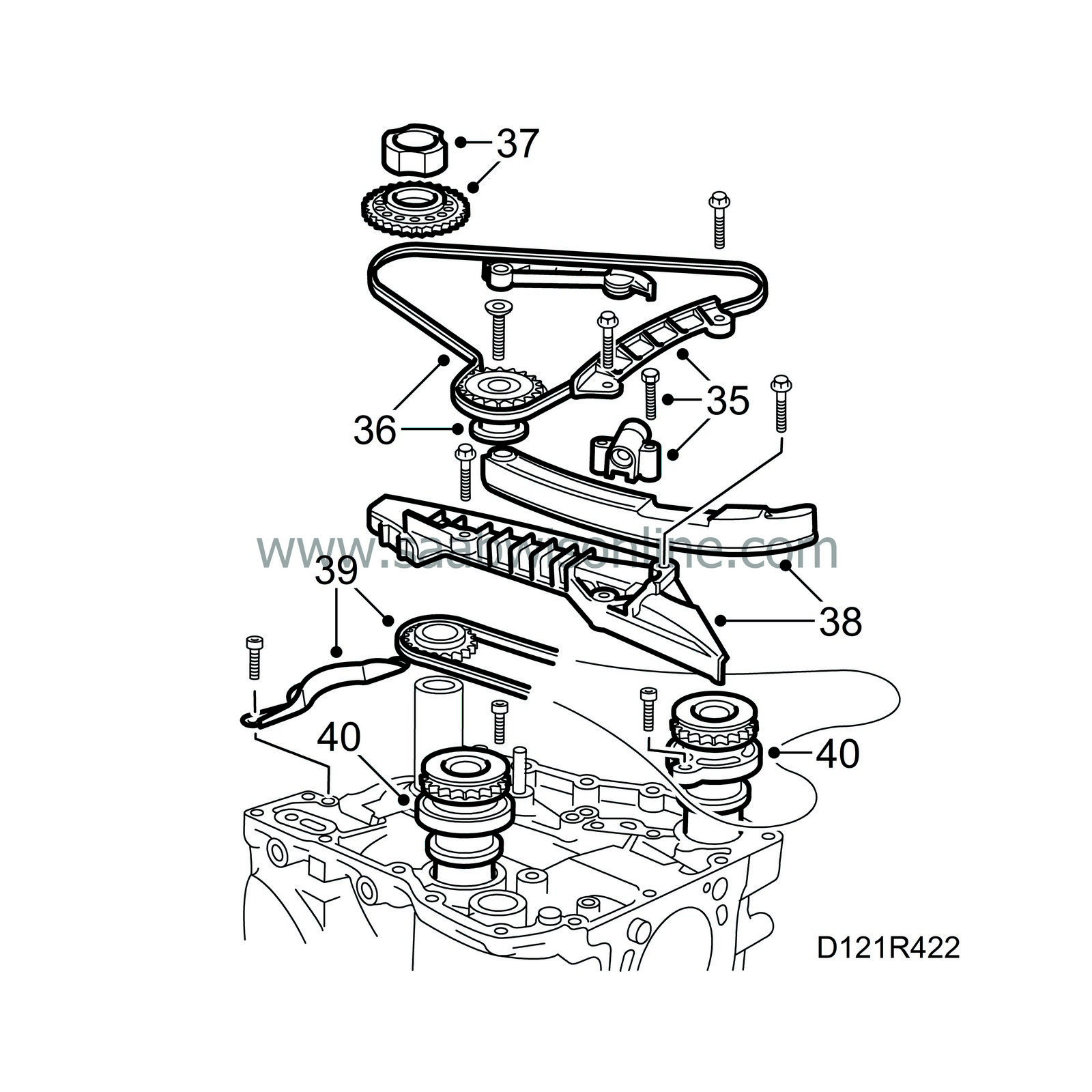
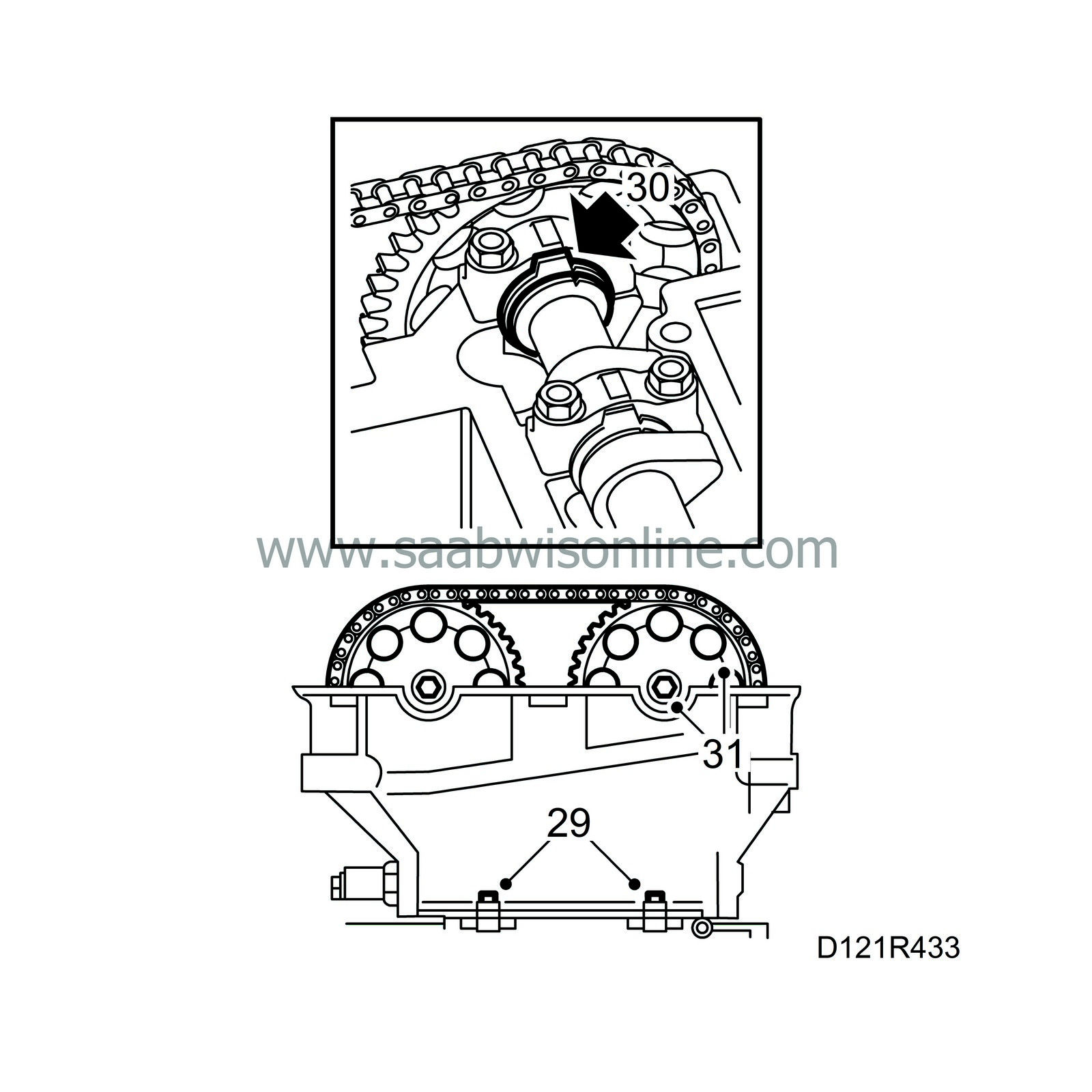
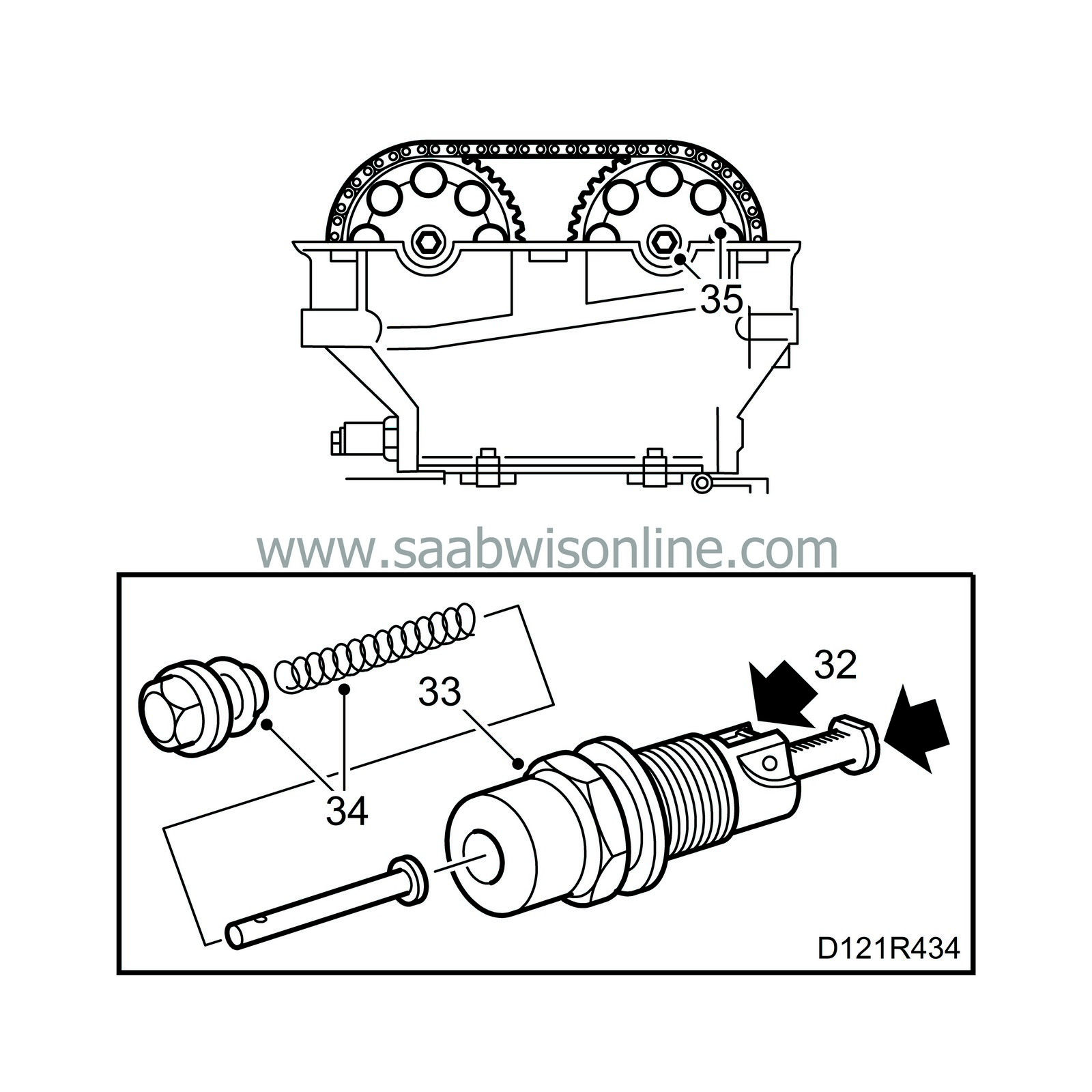
Remove the chain tensioner. first remove the plug, then use a 27 mm socket. Measure and not the length of the chain tensioner.
|
|
31.
|
Remove the camshaft sprockets, holding each camshaft steady with a spanner applied to the end of it.
|
|
32.
|
Fit a rubber band round the chain guides and remove the cylinder head. Start with the bolts in the timing cover. Collect the bolts with a magnet.
|
|
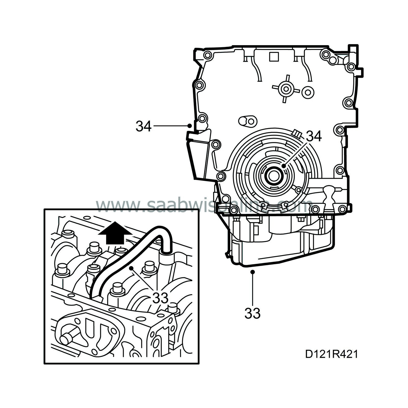
33.
|
Turn the engine to a suitable working position and remove the oil sump and the pipe to the oil adapter.
|
|
34.
|
Remove the oil pump and timing cover.
|
|
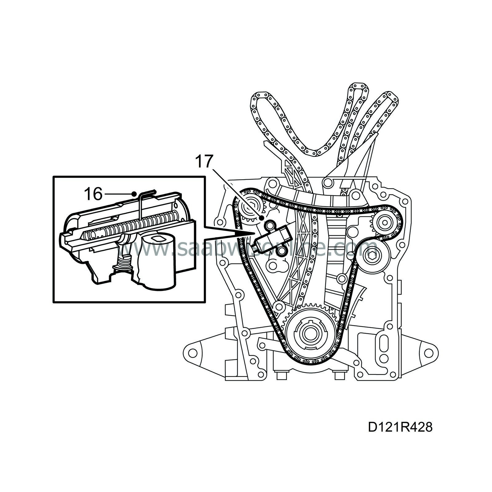
35.
|
Remove the top chain guide and chain tensioner for the balancer shaft chain.
|
|
36.
|
Remove the idler pulley and the balancer shaft chain.
|
|
37.
|
Remove the oil pump driver and sprocket from the crankshaft.
|
|
38.
|
Remove the balancer shaft and timing chain guides.
|
|
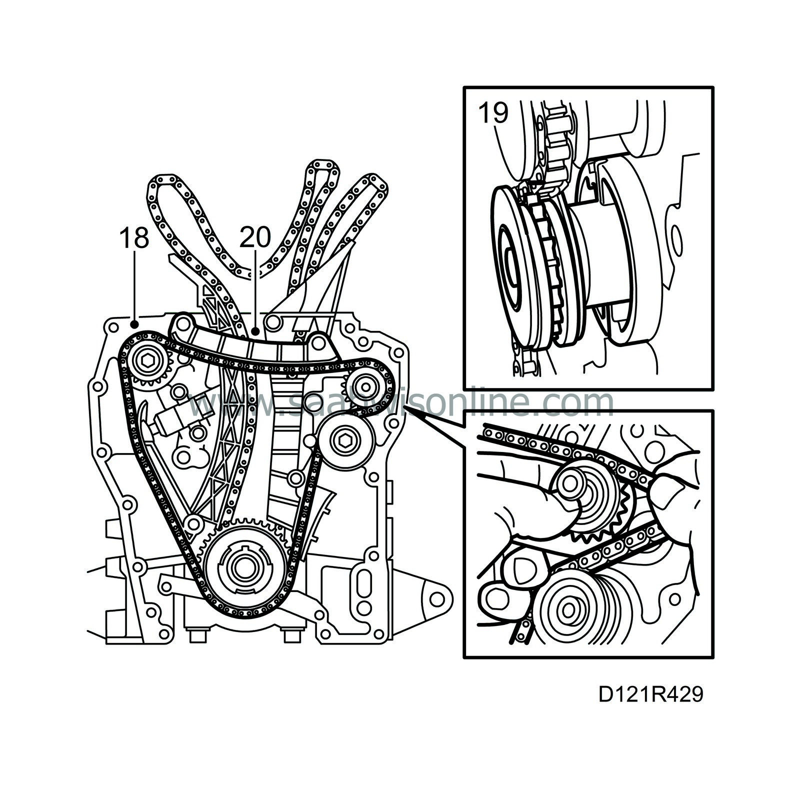
39.
|
Remove the timing chain guard and remove the chain complete with sprocket.
|
Important
|
|
Turn the balancer shafts 180°, so that the weights are pointing up. Remove them carefully so the inner bearing bushes are not damaged.
|
|
|
|
|
40.
|
Remove the balancer shafts complete with sprockets and bearing housings.
|
|
41.
|
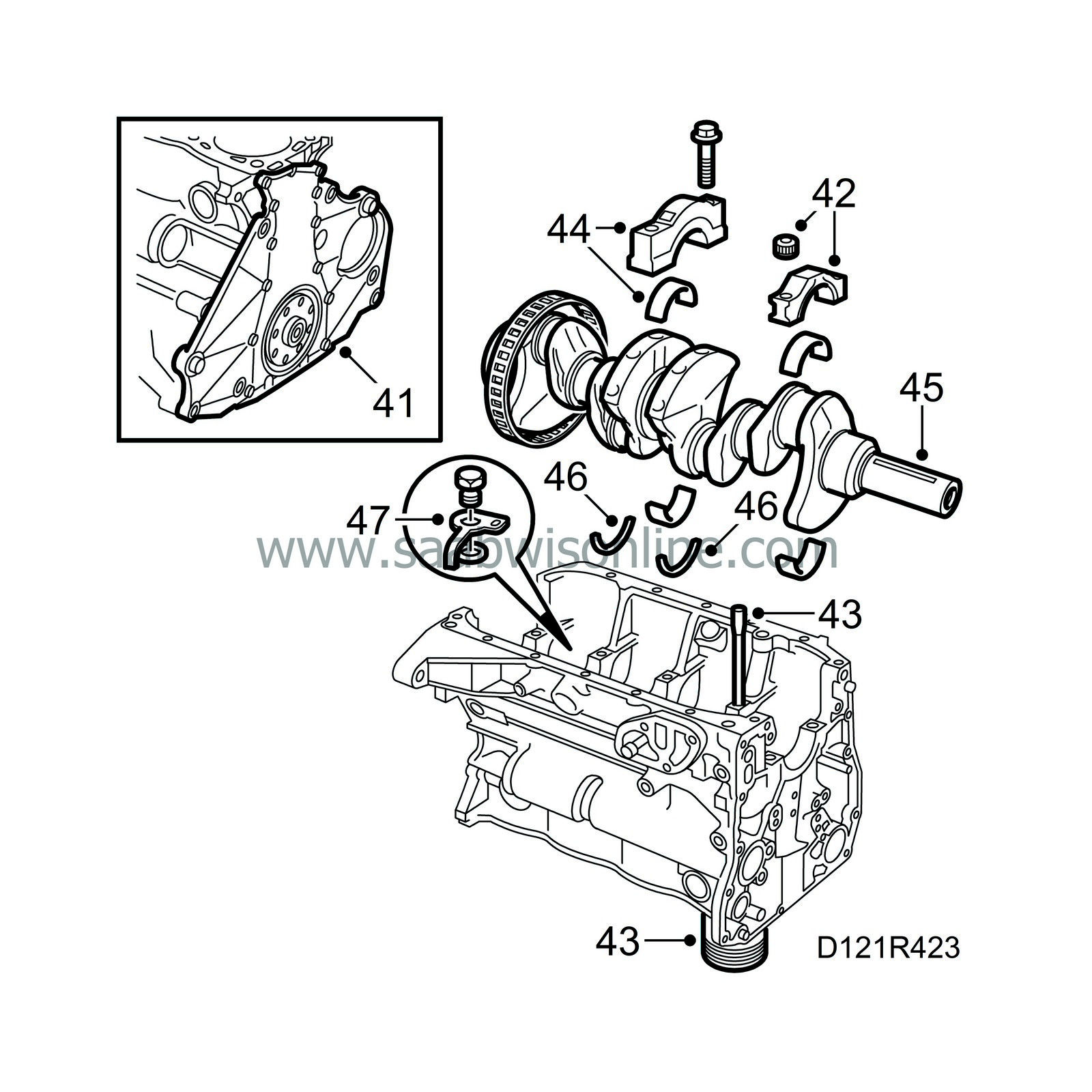
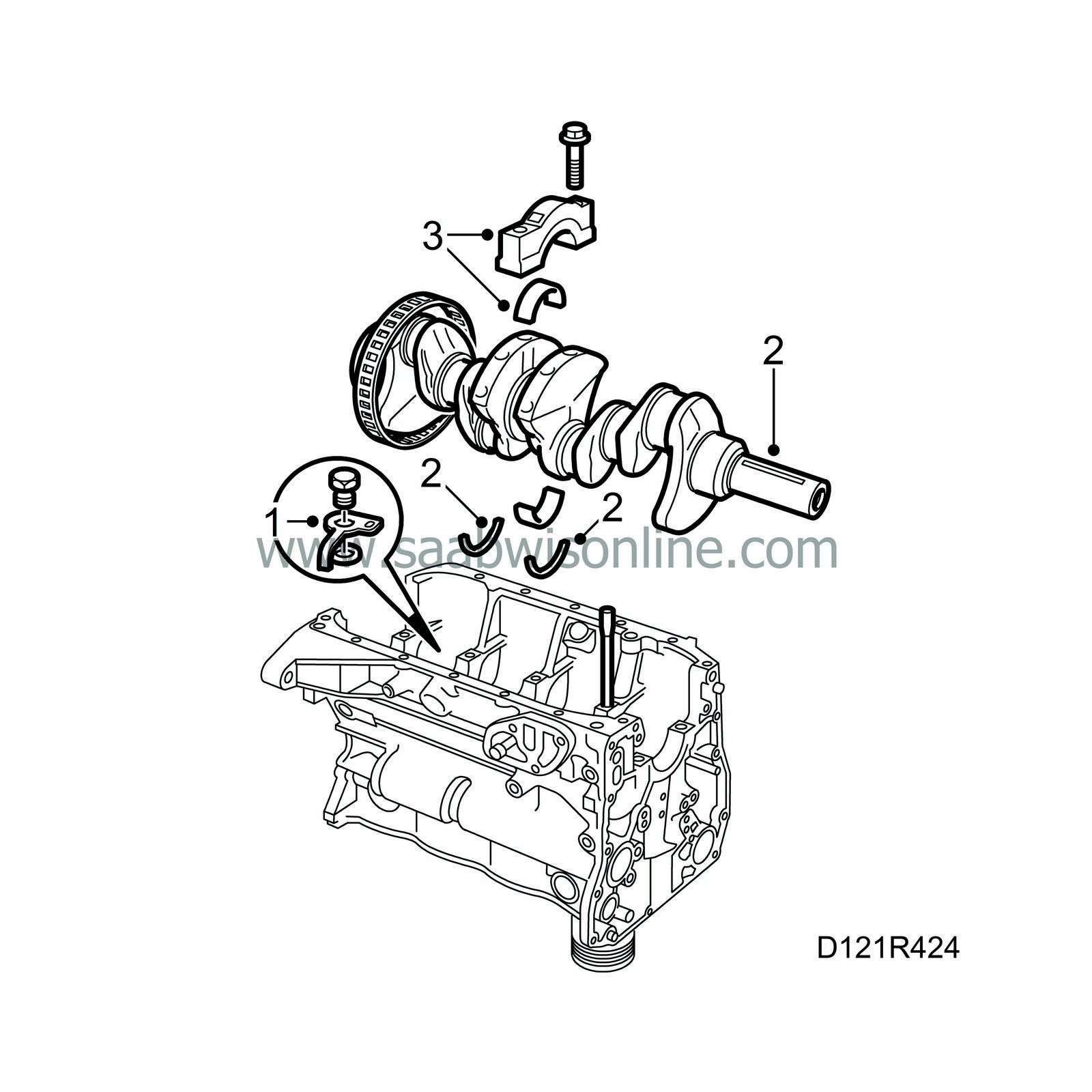
Remove the end plate.
|
Important
|
|
When removing caps and bearing races, make sure that parts are kept in such a way that they can be refitted with the right parts in the right place.
|
|
|
|
|
42.
|
Remove any carbon deposits from the edges, turn the engine into a convenient position and remove all big-end bearing caps.
|
Note
|
|
Use a 12 point 14 mm socket.
|
|
|
44.
|
Remove all main bearing caps and lift out the crankshaft.
|
Important
|
|
The field rotor flange must be treated very carefully. Make sure the main bearing adjustment sleeves are unscrewed, if they are not fastened.
|
|
|
|
|
45.
|
Remove the slotted ring.
|
|
46.
|
Remove all the bearing shells for both the main bearings and big-end bearings. Also remove the two thrust washers from main bearing no. 3.
|
|
47.
|
Remove the piston cooling nozzles.
|
|
To assemble the engine block
|
All engine components should be thoroughly cleaned before fitting.
|
1.
|
Fit the piston cooling nozzles. Place all main bearings in their correct positions and coat them with oil.
Tightening torque, piston cooling nozzle: 18 Nm (13 lbf ft).
|
Important
|
|
The field rotor flange must be treated very carefully. Make sure the main bearing adjustment sleeves are unscrewed, if they are not fastened.
|
|
|
|
|
2.
|
Fit the slotted ring, place the crankshaft in position and fit the two thrust washers at the main bearing between the No. 2 and No. 3 cylinders. Fit the washers with the embossed side facing towards the main bearing so that the bearing surface is the right way round.
|
|
3.
|
Lubricate and fit all main bearing caps in their correct places, making sure that they are the right way round.
Tightening torque: 20 Nm + 70 (15 lbf ft + 70).
|
|
4.
|
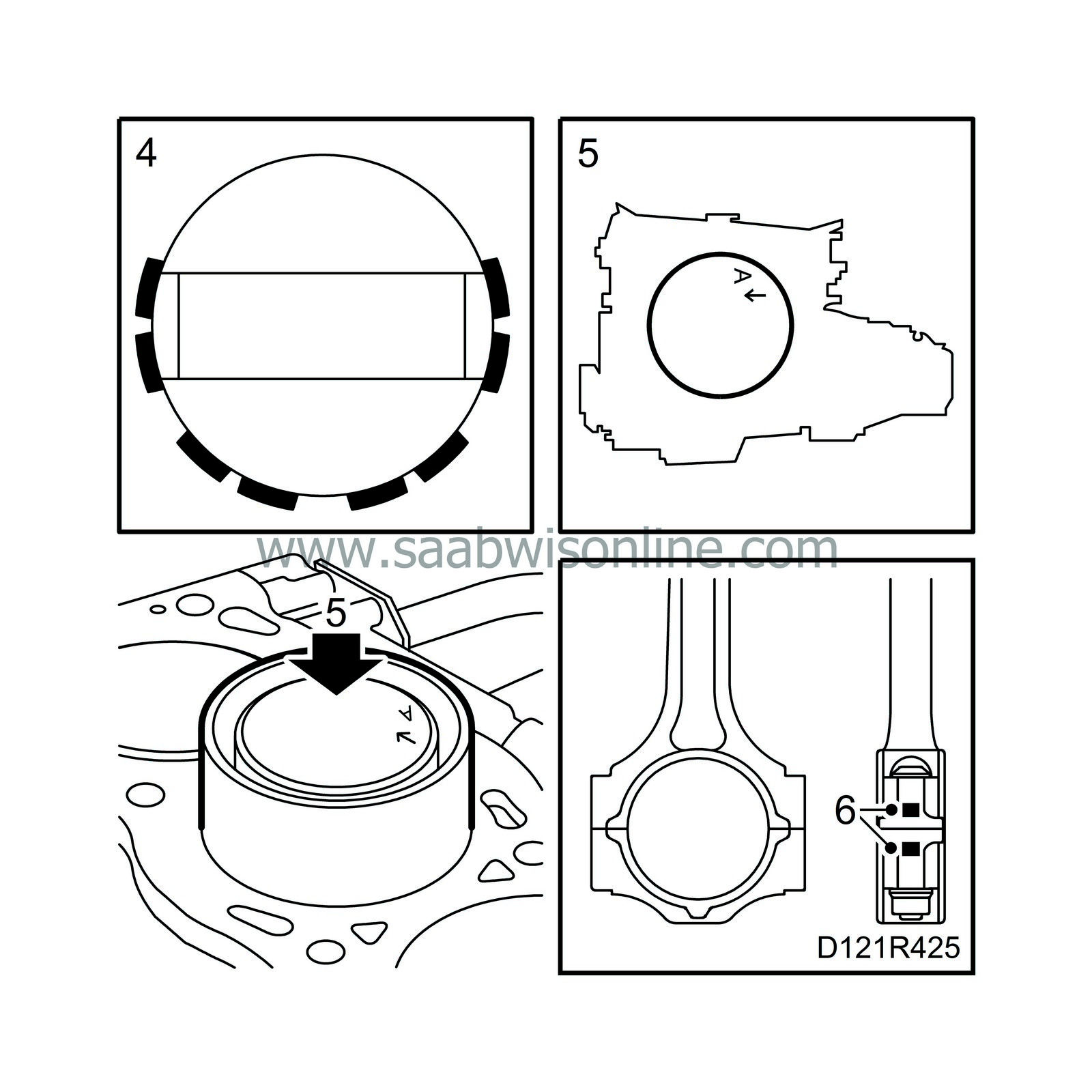
Turn the compression rings so that the gaps in the rings are moved 180
°
and located directly opposite the gudgeon pin ends. Also make sure that the upper and lower spring gap on the three-piece oil scraper ring are not lined up opposite each other.
|
|
5.
|
Fit protective collars 75 19 531 on the crankshaft studs, oil the pistons and rings, then fit the pistons in their respective cylinders. The arrow markings on the piston crown should be turned towards the engine's transmission side. Use piston fitting tool 78 62 287 and carefully tap down the pistons in the bores.
|
|
6.
|
Lubricate and fit all big-end bearing caps in their original positions, making sure that they are the right way round (number to number, groove in shell to groove in shell).
Tightening torque: 20 Nm + 70 (15 lbf ft + 70).
|
|
7.
|
Apply a bead of flange sealant, part no. 93 21 795, approximately 1 mm wide to the mating face of the end plate and fit the end plate. Be careful with the sealant.
|
|
8.
|
Align the crankshaft with the wedge straight up (corresponding to the 0 mark on the crankshaft pulley).
|
|
9.
|
Loosely fit the flywheel or, alternatively, the companion disc. Use thread locking adhesive, part no. 74 96 292, to the bolts. Make sure the marking is straight up towards the cylinder head.
|
|
10.
|
Fit the disc and pressure plate.
|
|
11.
|
Fit the flywheel locking attachment 83 94 868 and tighten the bolts.
Tightening torque, flywheel or companion disc: 20 Nm +50° (15 lbf ft)+50°
|
|
12.
|
Lubricate the bearing surfaces on the balancer shafts and in the bearing housings and insert the balancer shafts into their respective tunnels, taking the utmost care to avoid damaging the bearing shells inside.
|
Important
|
|
Fit the shaft with the small thrust ring marked INL on the inlet side. Fit the shaft with the large thrust ring marked EXH on the exhaust side.
|
|
|
|
|
13.
|
Check the timing chain and fit the chain guard and chain onto the crankshaft end with the markings facing each other. Screw on the safety plate.
|
|
14.
|
First fit the fixed chain guide, which is common to the timing chain and balancer shaft chain, and then the pivoted chain guides for the timing and balancer shaft chains.
|
|
15.
|
Fit the balancer shaft sprocket and the oil pump driver onto the crankshaft end.
|
|
16.
|
Cock the balancer shaft chain tensioner and insert a paper clip or similar object through the hole in the cylinder to prevent triggering of the tensioner. Before this, check that the plunger is turned to the position where it really is pressed out by the spring.
|
|
17.
|
Fit the chain tensioner.
Tightening torque: 10 Nm (7 lbf ft).
|
Important
|
|
It is extremely important for the function that the correct tightening torque is applied when fitting.
|
|
|
|
|
18.
|
Inspect the balancer shaft chain and fit it and the idler sprocket so that the upper setting markings behind the balancer shaft sprocket and bearing housing are aligned with each other. Tauten the chain between the crankshaft and balancer shafts. Fit the idler sprocket last of all. Hold the bolt in place with your thumb, mesh the teeth of the sprocket with the chain and "roll" it into position along the chain.
|
|
19.
|
Check the marking on the balancer shaft sprocket and remove the flywheel locking attachment.
|
|
20.
|
Setting: Fit the timing cover using two bolts only and do not tighten them. Mount the crankshaft pulley. Rotate the pulley one revolution. Reset the pulley relative to the timing cover. Remove the timing cover and crankshaft pulley carefully, making sure that the crankshaft does not move, and check the settings of the balancer shafts.
|
|
21.
|
Make sure the mating face on the timing cover is completely clean. Apply a bead of flange sealant, part no. 93 21 795, approx. 1 mm wide on the timing cover. Apply the bead in the centre of the sealing surfaces.
|
|
22.
|
Fit the timing cover. Make sure the upper plane of the cover is aligned with the engine block plane. Apply a 10-20 mm long bead of Loctite 518, part no. 93 21 795, on the inside of the timing cover contact surfaces (towards the cylinder head).
Tightening torque: 22 Nm (16 lbf ft).
|
|
23.
|
Fit the flywheel locking attachment and crankshaft pulley. Remove the flywheel locking attachment.
Tightening torque: 175 Nm (130 lbf ft).
|
|
24.
|
Fit the oil pump pressure pipe using new O-rings and check that there are no impurities or other foreign matter in the oil sump.
|
|
25.
|
Fit the adapter housing and oil filter. Fit new O-rings lubricated with engine oil.
|
|
26.
|
Check that the strainer of the oil sump is clean. Fit using new O-rings.
|
|
27.
|
Make sure the mating surface on the oil sump is completely clean and apply an even coat of flange sealant, part no. 93 21 795. Turn over the engine and fit the oil sump.
Tightening torque: 22 Nm (16 lbf ft).
|
|
28.
|
Thoroughly clean all gasket surfaces. Apply a 2 mm thick, 10-20 mm long bead of Loctite 518, part no. 93 21 795, on the inside of the timing cover's upper contact surface (towards the cylinder head). Turn the engine in the stand, rotate the crankshaft 45° to lower the pistons.
Fit a rubber band round the chain guides and mount the cylinder head with a new gasket. Check that it is correctly seated on the guide sleeves and that the chain is not trapped.
Tighten the cylinder head bolts in three stages:
Stage I: 40 Nm (30 lbf ft)
Stage II: 60 Nm (44 lbf ft)
Stage III: A further 90°
Tighten the bolts in the order shown in the illustration.
|
|
29.
|
Fit the two bolts between the timing cover and cylinder head.
Tightening torque: 22 Nm (16 lbf ft).
|
|
30.
|
Remove the rubber band and check that the camshafts are in alignment with their setting marks and turn the crankshaft back to the 0 mark.
|
|
31.
|
Fit the camshaft sprockets and chain. Start with the outlet camshaft. The marking on the wheels should be aligned with the chain markings. (Only applies to entirely zeroed engine.) Do not tighten the bolts yet!
|
|
32.
|
Prepare the chain tensioner for mounting by pressing down the catch and pressing in the chain tensioner.
|
|
33.
|
Fit the chain tensioner, using a 27 mm socket.
Tightening torque: 63 Nm (47 lbf ft).
|
|
34.
|
Fit the chain tensioner plug with push rod and spring.
Tightening torque: 22 Nm (16 lbf ft).
|
|
35.
|
Check that the chain is correctly seated in the guides. Rotate the crankshaft two complete turns and check the settings of the crankshaft pulley and camshafts.
|
|
36.
|
Tighten the camshaft sprocket bolts.
Tightening torque: 63 Nm (47 lbf ft).
|
|
37.
|
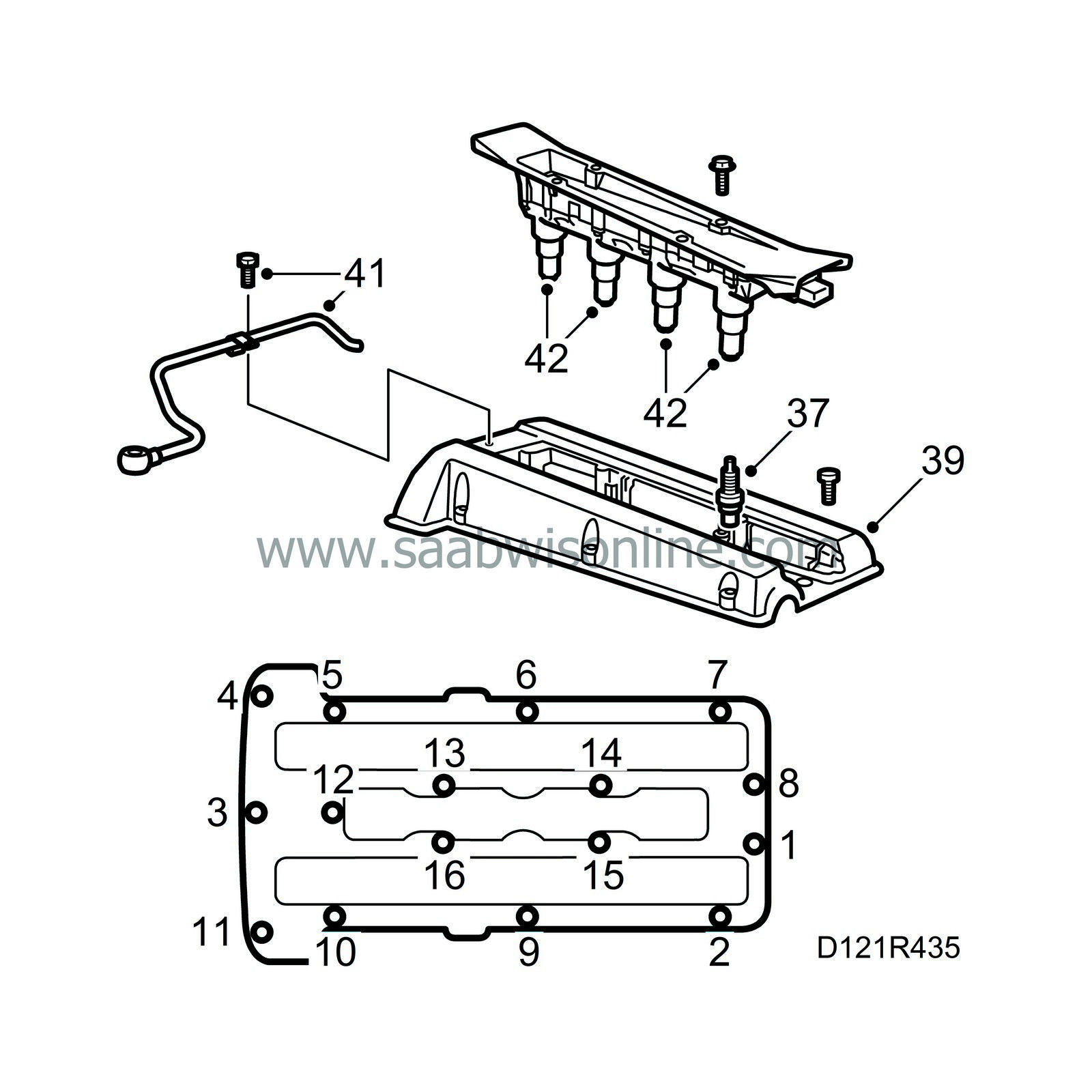
Check the condition and play of the spark plugs. Replace them if necessary. Fit the spark plugs.
Tightening torque: 28 Nm (21 lbf ft).
|
|
38.
|
Clean the sealing surface of the camshaft cover with benzine.
|
|
39.
|
Apply a thin layer of gasket adhesive, part no. 46 20 084, in the outer and inner gasket seats on the camshaft cover. Fit the gaskets.
|
|
40.
|
Apply oil to the opening on the camshaft cover and fit the cover, starting at the opening. Then, tighten the bolt located furthest to the front at the timing chain end. Continue all the way round the outside and inside. See illustration.
Tightening torque: 15 Nm (11 lbf ft).
|
|
41.
|
Fit the banjo pipe to the charge air pipe.
|
|
42.
|
Lubricate the ignition discharge module contact surfaces with Krytox, part no. 30 19 312. Fit the ignition discharge module.
Tightening torque: 11 Nm (8 lbf ft).
|
|
43.
|
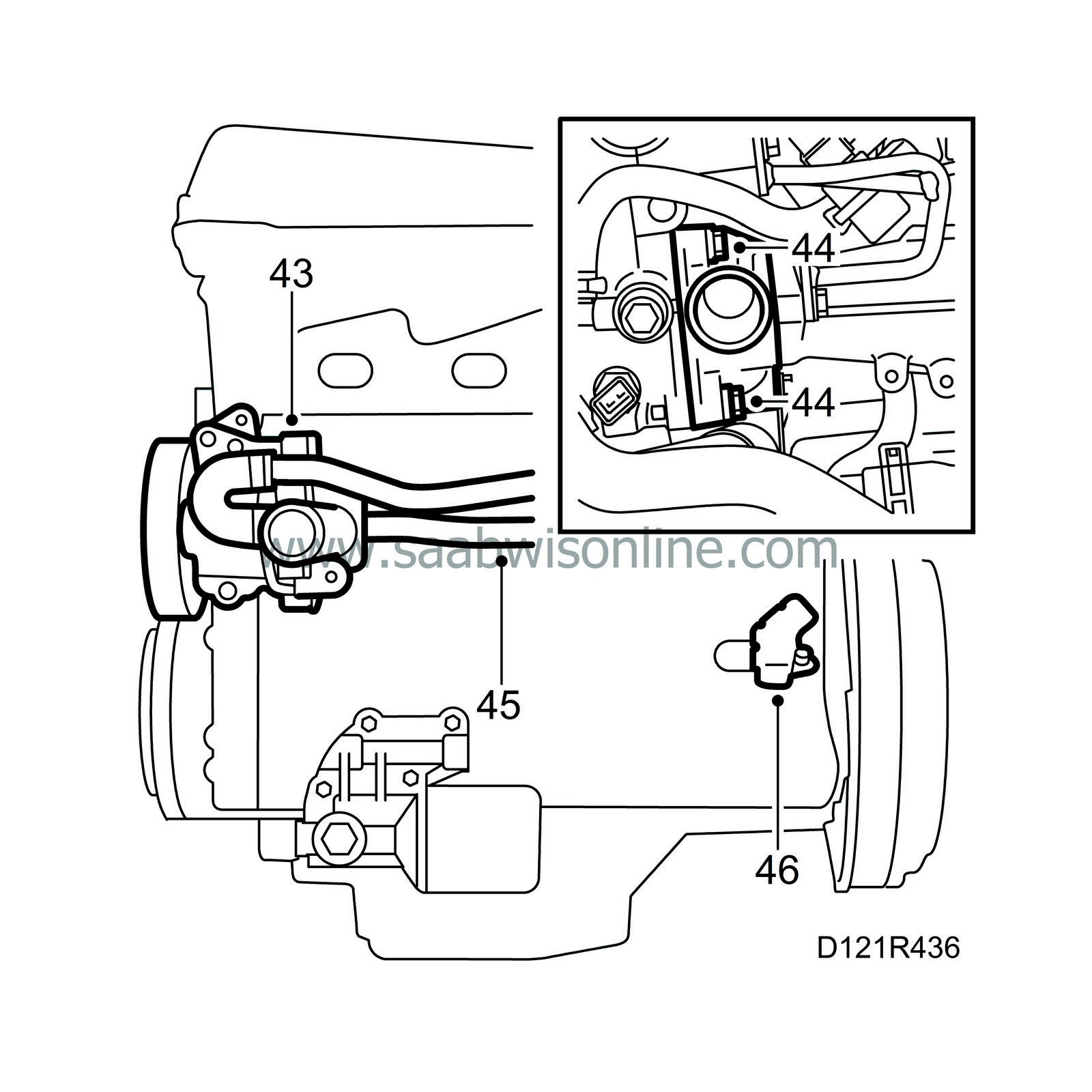
Check the coolant pump O-rings. Replace as necessary.
Clean the hole in the block and fit the connector with the large vane pointing horizontally towards the flywheel side.
Lubricate the O-rings with acid-free Vaseline and fit the coolant pump and pipe.
|
|
44.
|
Fit the thermostat and thermostat housing.
|
|
45.
|
Fit the input and output pipes of the water pump. Be aware of the bolt lengths.
|
|
46.
|
Fit the crankshaft position sensor with protective cover.
|
|
47.
|
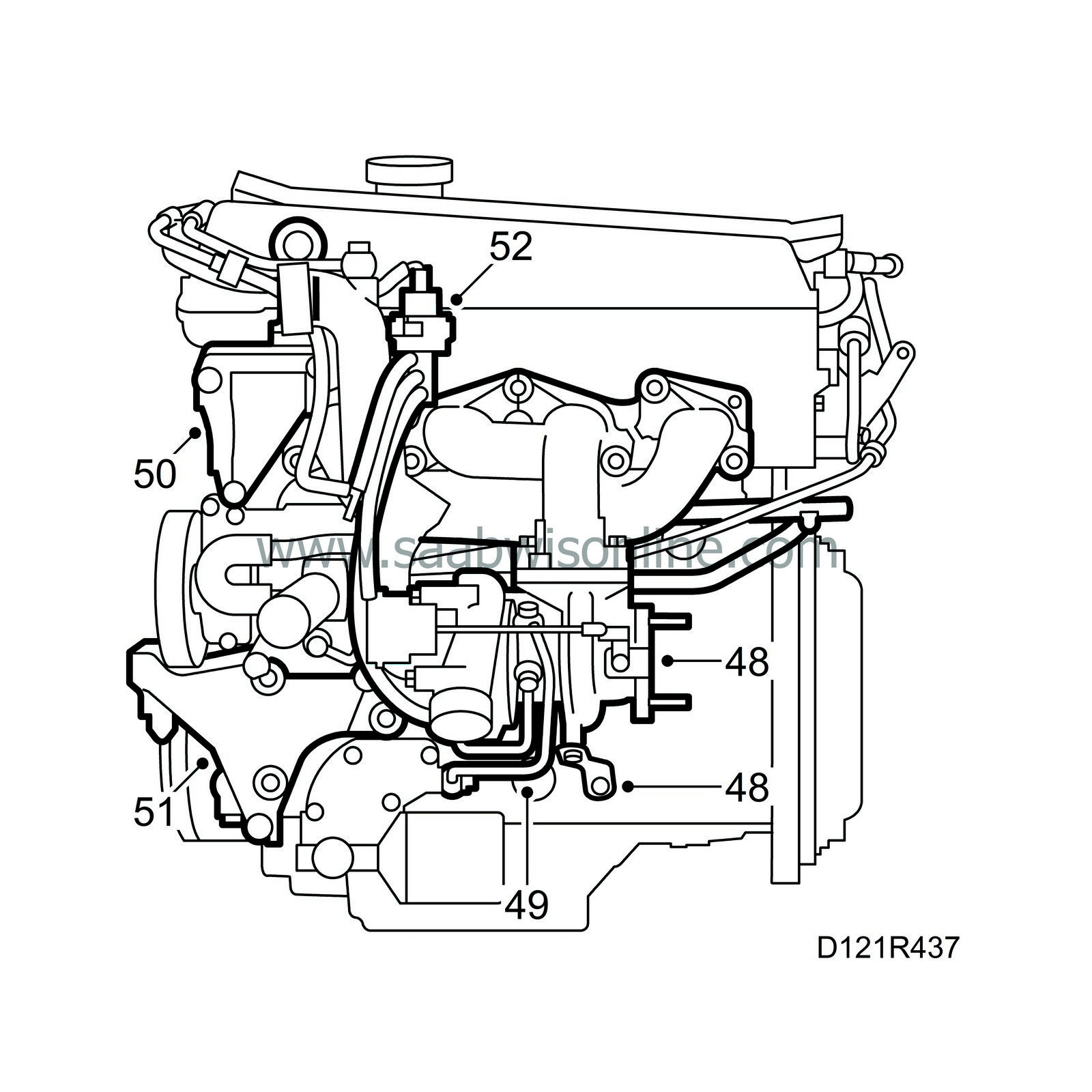
Clean the gasket surfaces and fit a new exhaust manifold gasket.
|
|
48.
|
Fit the turbocharger with exhaust manifold and stay.
Tightening torque: 25 Nm (19 lbf ft).
|
|
49.
|
Connect the coolant and oil pipes.
|
Important
|
|
The rubber gaskets must be placed closest to the adapter housing and water pump respectively in the cylinder head.
|
|
|
|
|
50.
|
Fit the servo pump bracket.
|
|
51.
|
Fit the A/C compressor bracket.
|
|
53.
|
Clean all gasket surfaces between the intake manifold and cylinder head.
|
|
54.
|
Align the intake manifold gaskets with the aid of the outer retaining bolts and fit the intake manifold.
Tightening torque: 22 Nm (16 lbf ft).
|
Important
|
|
Cars with intermediate piece have a gasket on both sides of the intermediate. (Not applicable to LEV cars.)
|
|
|
|
|
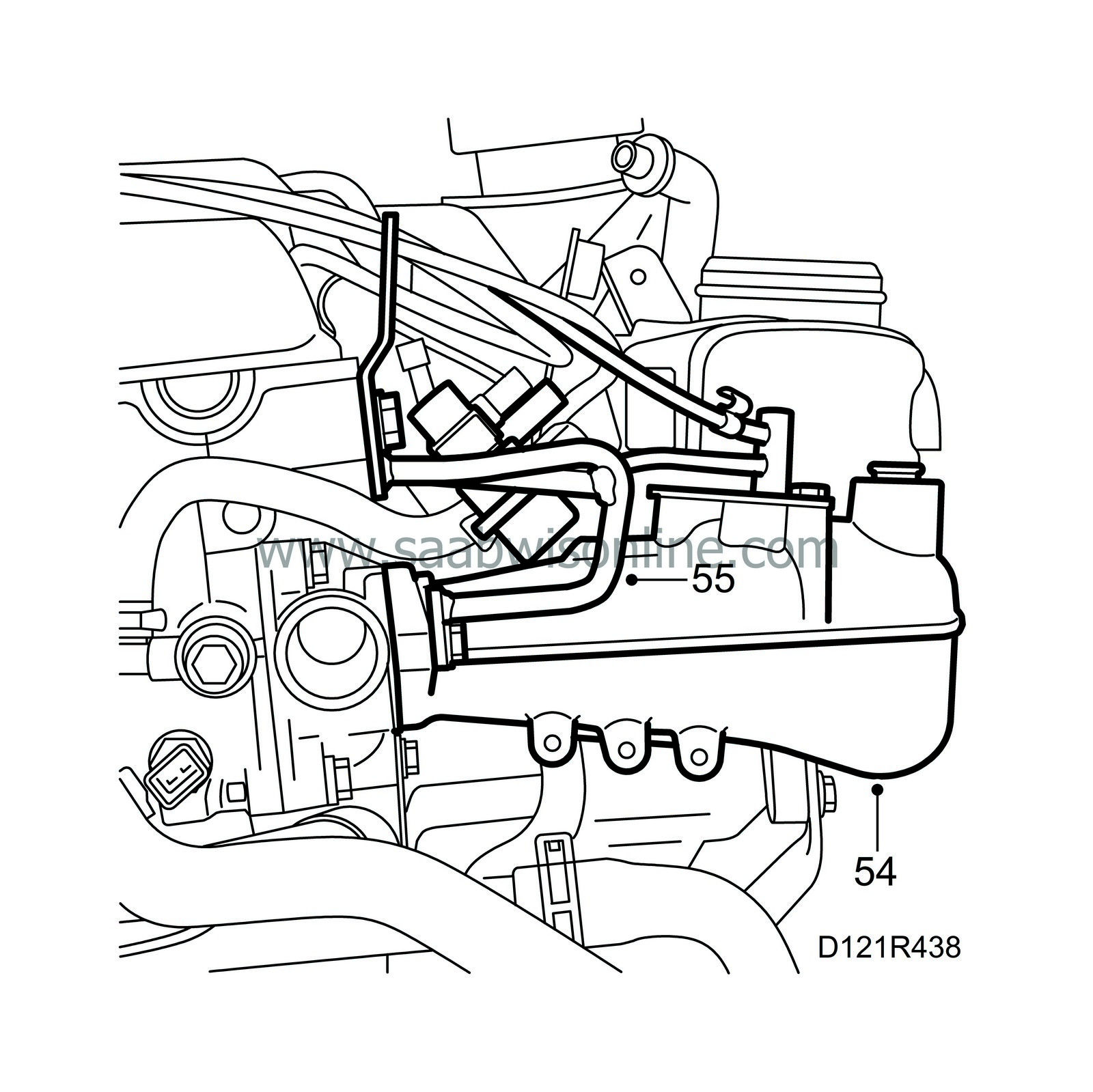
55.
|
(B235R) Fit the rear lifting eye. Fit the fuel distribution pip with clips.
|
|
56.
|
Reconnect the hoses from the throttle body.
|
|
57.
|
Fit the oil filler pipe with mounting. Fit a new O-ring.
|
|
58.
|
Fit the connector housing bracket at the intake manifold.
|
|
59.
|
Man: Fit the gearbox with flywheel cover plate.
|
|
60.
|
Aut: Fit the gearbox without cover plate
|
|
61.
|
Connect a lifting sling and lift the engine from the stand to the subframe.
|
|
63.
|
Fit the rear engine mounting bracket and the gearbox retaining bolts. Remove the plug.
|
|
65.
|
Position the engine on the subframe and fit the rear engine mounting, tightening it with a torque wrench.
Tightening torque: 50 Nm (37 lbf ft).
|
|
66.
|
Remove the plug and replace the packing box in the gearbox. Fit the bearing bracket with intermediate shaft and inner driver shaft. Use fitting tool 83 95 162. Check the fluid level in the gearbox and top up as necessary.
|
|
67.
|
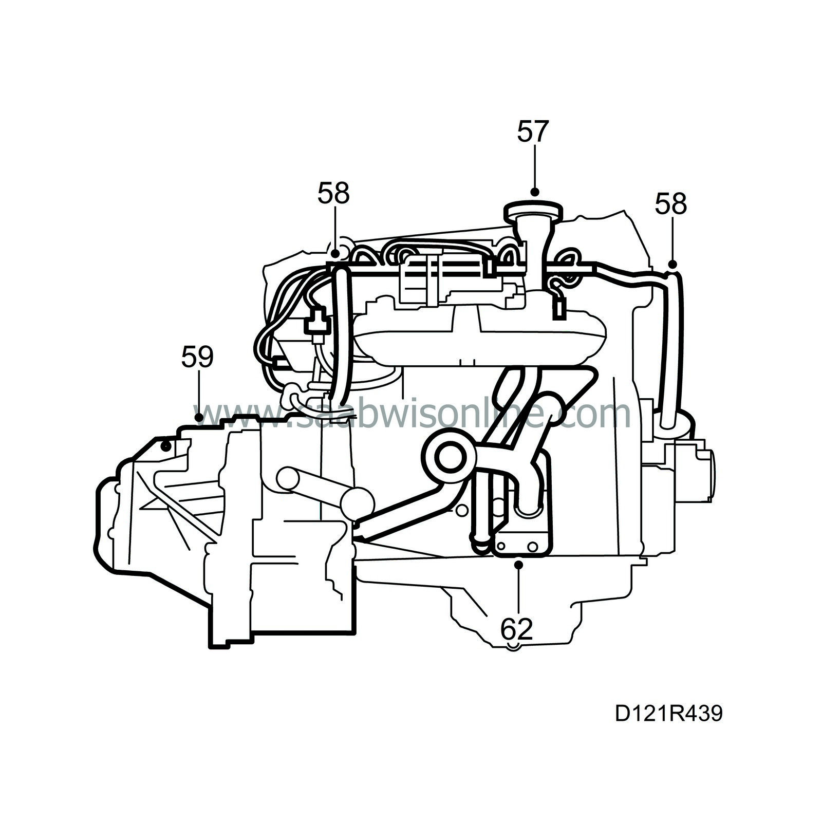
Fit the oil trap and connect its hoses.
|
|
68.
|
Fit the generator bracket.
|
|
69.
|
Fit the intake manifold stay.
|
|
70.
|
Fit the rail with wiring harness.
|
|
71.
|
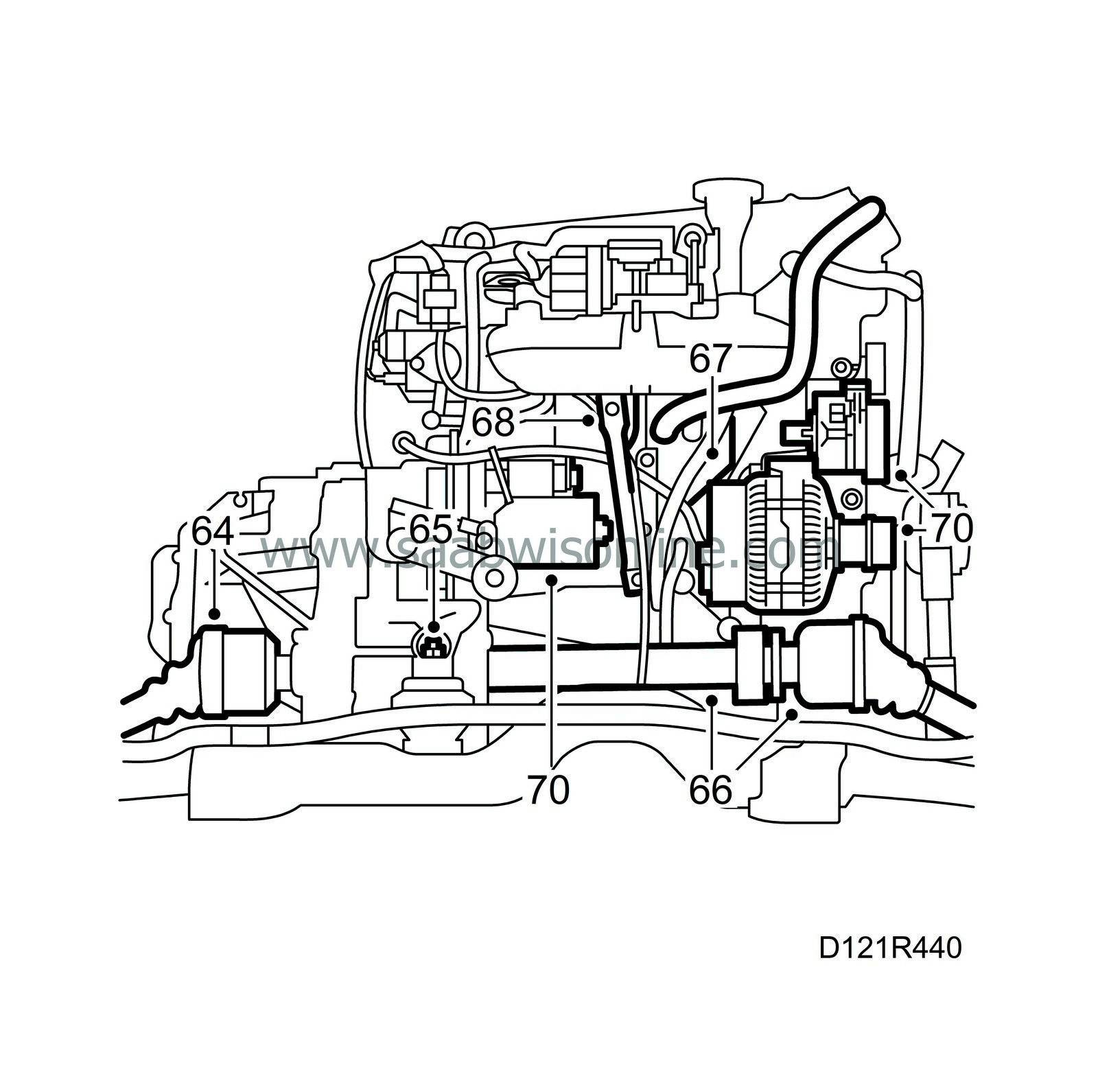
Fit and connect the generator.
|
|
72.
|
Fit the starter motor and belt tensioner.
|
|
73.
|
Check that the oil plug is tight. Loosely fit the belt on the auxiliary unit. The power train is now ready for fitting in the car.
Tightening torque 25 Nm (19 lbf ft).
|
|
Replacement of balancer-shaft bearings
|
To remove
|
1.
|
Remove the blanking-off washer.
|
|
2.
|
Insert press tool 83 94 470 from the flywheel end and connect the pull rod with a nut.
|
|
3.
|
Carefully remove the bearing by slowly tightening the nut.
|
To fit
|
1.
|
Clean the bearing surface in the cylinder block.
|
|
2.
|
Fit the bearing on press tool 83 94 470 .
|
|
3.
|
Insert the fitting tool from the flywheel end and connect the pull rod with nut.
|
|
4.
|
Tighten the nut until the mark on the tool is 5 mm from the edge of the hole for the blanking-off washer. The bearing is now in the correct position.
|
|
5.
|
Dismantle and remove the tool.
|
|
6.
|
Check that the oil passage is open by blowing compressed air through the centre main bearing.
|
|
7.
|
Fit a new blanking-off washer.
|


