To assemble the engine block
|
|
To assemble the engine block
|
Wash all sealing surfaces with benzine, making sure that they are perfectly clean.
|
1.
|
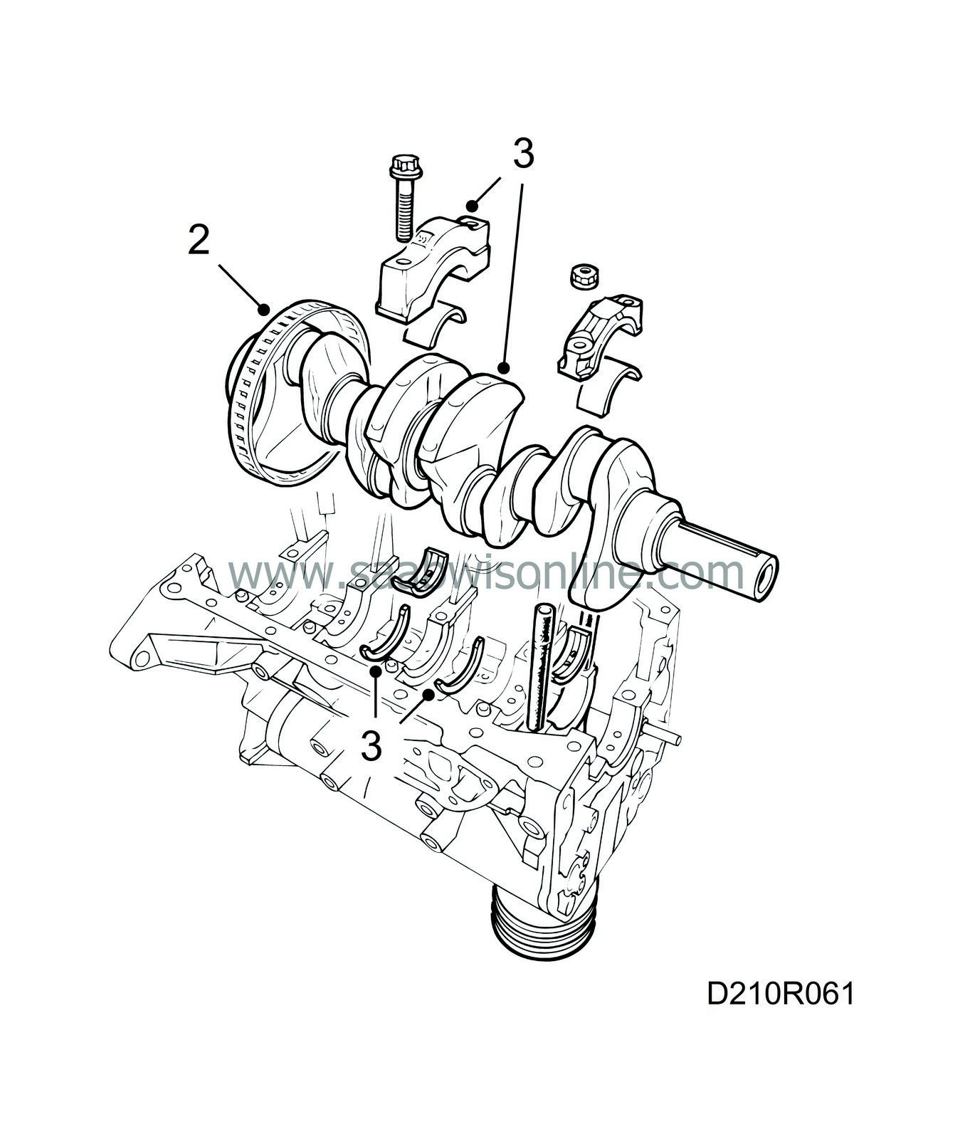
Fit the piston cooling nozzles. Place all main bearings in their correct positions and coat them with oil.
Tightening torques:
Piston cooling nozzle: 18 Nm (13.3 lbf ft)
|
|
2.
|
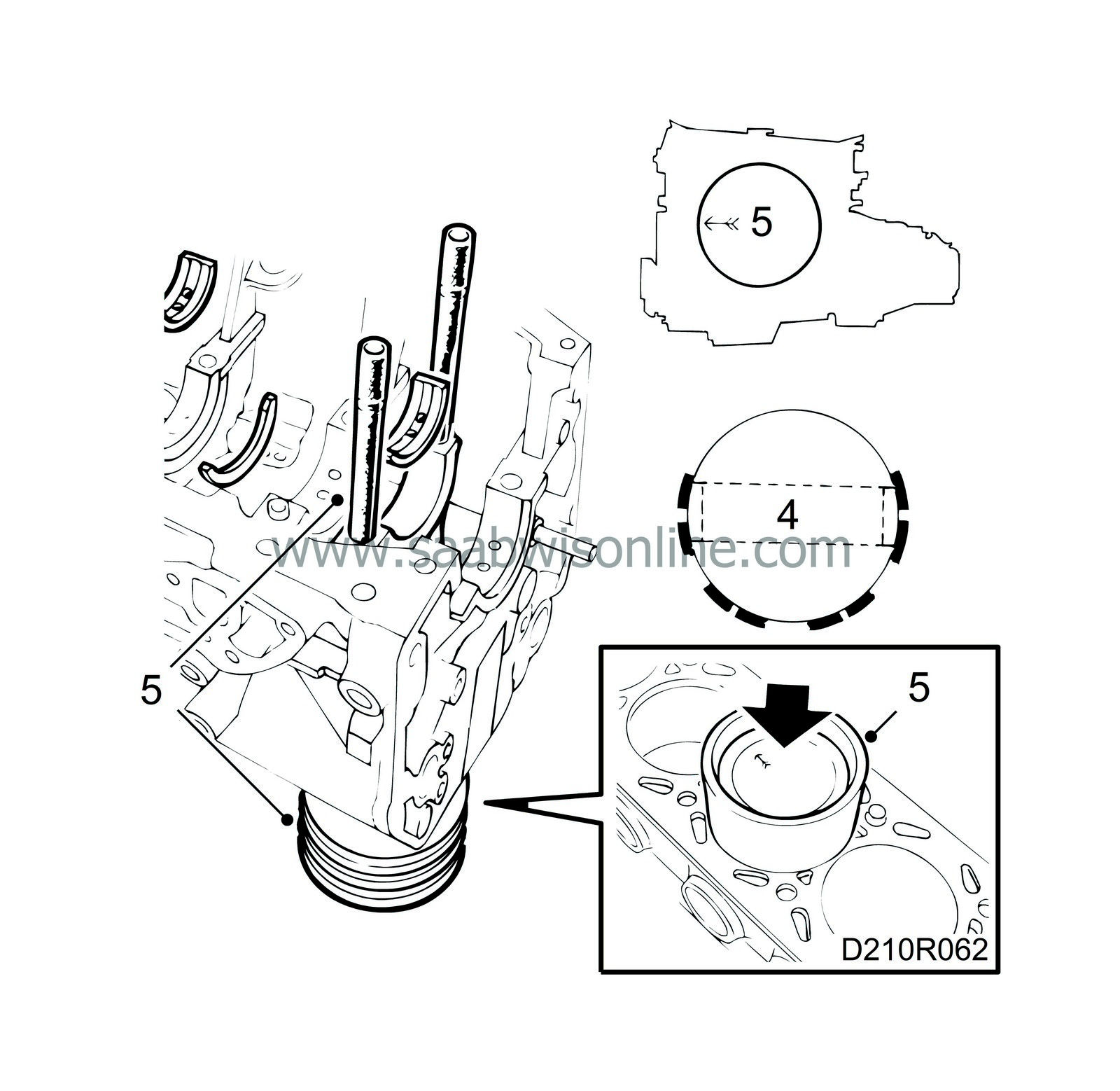
Fit the slotted ring, place the crankshaft in position and fit the two thrust washers at the main bearing between the No. 2 and No. 3 cylinders. Fit the washers with the embossed side facing towards the main bearing so that the bearing surface is the right way round.
|
Important
|
|
Observe the utmost care when handling the slotted ring.
|
|
|
|
|
3.
|
Lubricate and fit all main bearing caps in their correct places, making sure that they are the right way round.
Tightening torques:
20 Nm + 70° (15 lbf ft+ 70°)
|
|
4.
|
Turn the compression rings so that the gaps are staggered 180° and centred with the ends of the gudgeon pin. Also make sure that the gaps in the top and bottom rings of the three-part scraper ring are not in line with each other.
|
|
6.
|
Lubricate and fit all big-end bearing caps in their original positions, making sure that they are the right way round (number to number, groove in shell to groove in shell).
Tightening torques:
20 Nm + 70° (15 lbf ft + 70°)
|
|
7.
|
Apply a bead of flange seal, part no. 93 21 795, approximately 1 mm wide to the mating face of the end plate and fit the end plate. Be careful with the seal.
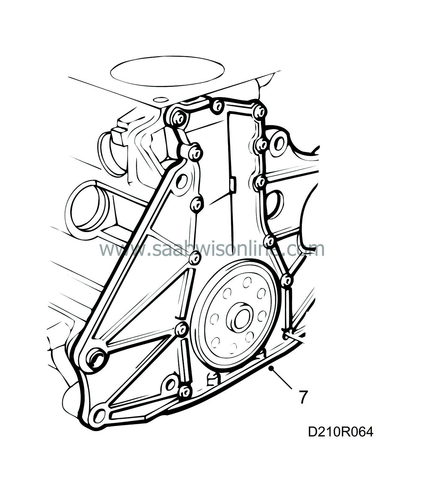
Tightening torque: 10 Nm (7 lbf ft)
|
|
8.
|
Loosely fit the flywheel or, alternatively, the companion disc. Use thread locking adhesive, part no. 74 96 292, to the bolts. Use
83 94 868 Flywheel locking attachment
and tighten the bolts.
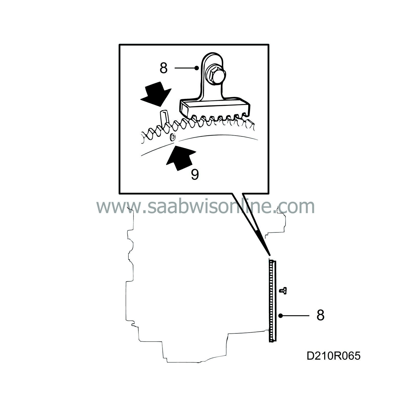
Tightening torque: 20 Nm + 50° (15 lbf ft + 50°)
|
|
9.
|
Align the 0-marking on the flywheel or, alternatively, the companion disc with the marking on the end plate.
|
|
10.
|
Lubricate the bearing surfaces on the balancer shafts and in the bearing housings and insert the balancer shafts into their respective tunnels, taking the utmost care to avoid damaging the bearing shells inside.
Tightening torques:
Bearing housing, balancer shafts to block 10 Nm (7 lbf ft)
|
Important
|
|
The shaft with the smaller thrust ring marked INL should be fitted on the inlet side of the engine. The shaft with the larger thrust ring marked EXH should be fitted on the exhaust side.
|
|
|
|
|
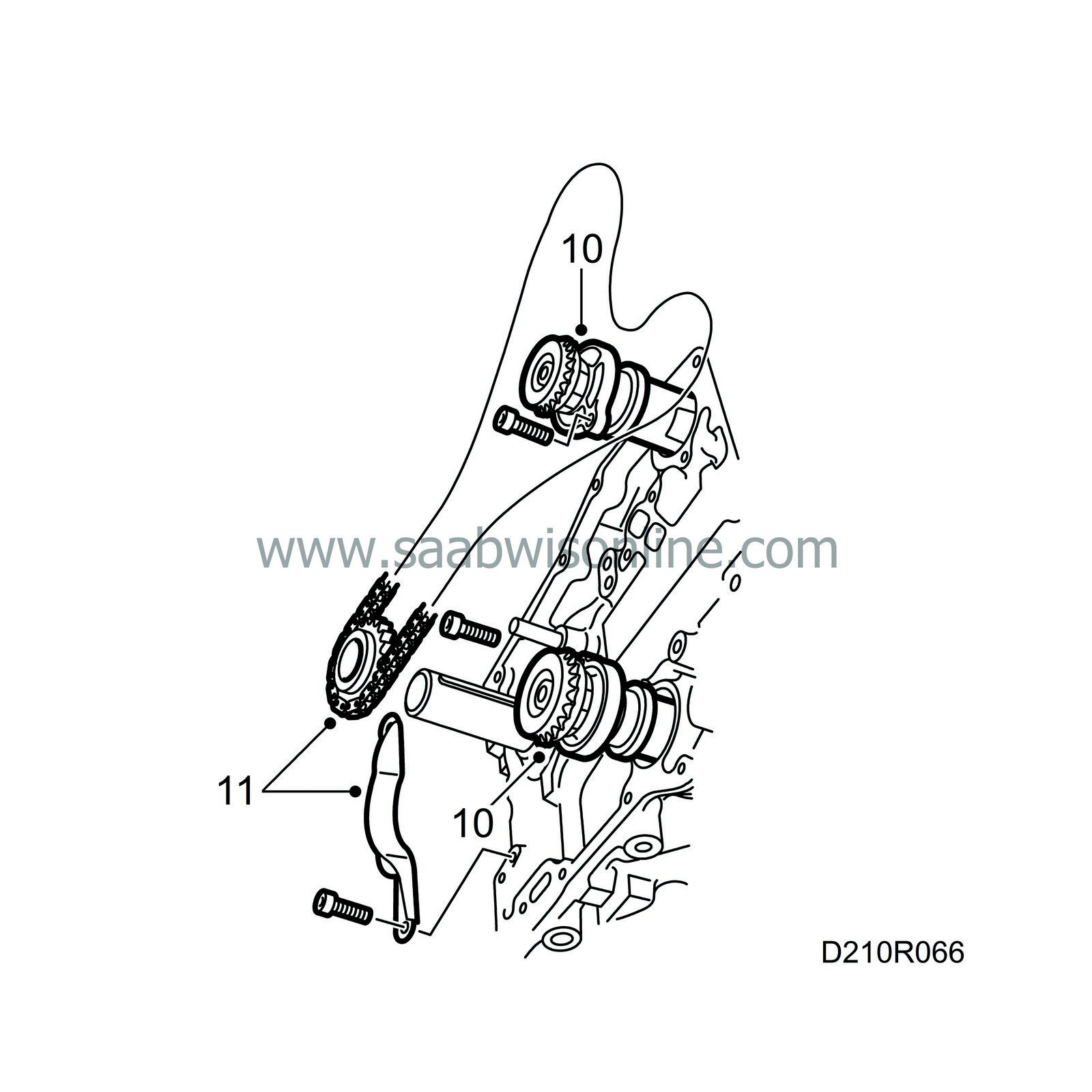
11.
|
Check the timing chain and fit the chain guard and chain onto the crankshaft end. Screw on the safety plate.
|
|
12.
|
Fit the fixed chain guard first, which is common to the timing chain and the balancer shaft chain, and then the pivoted chain guides for the timing chain and balancer shaft chains.
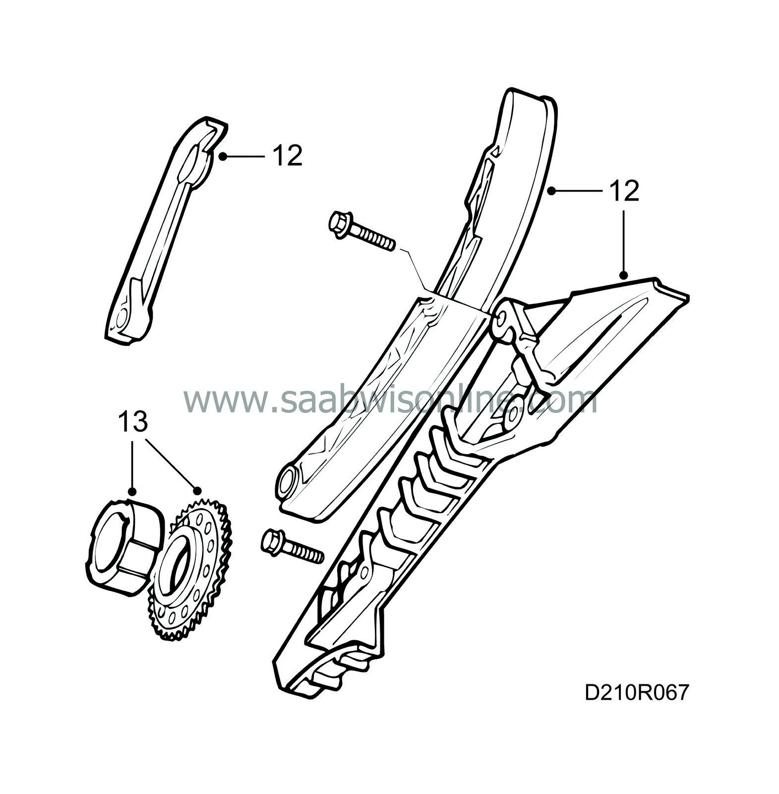
Tightening torque: 10 Nm (7 lbf ft)
|
|
13.
|
Fit the balancer shaft sprocket and the oil pump driver onto the crankshaft end.
|
|
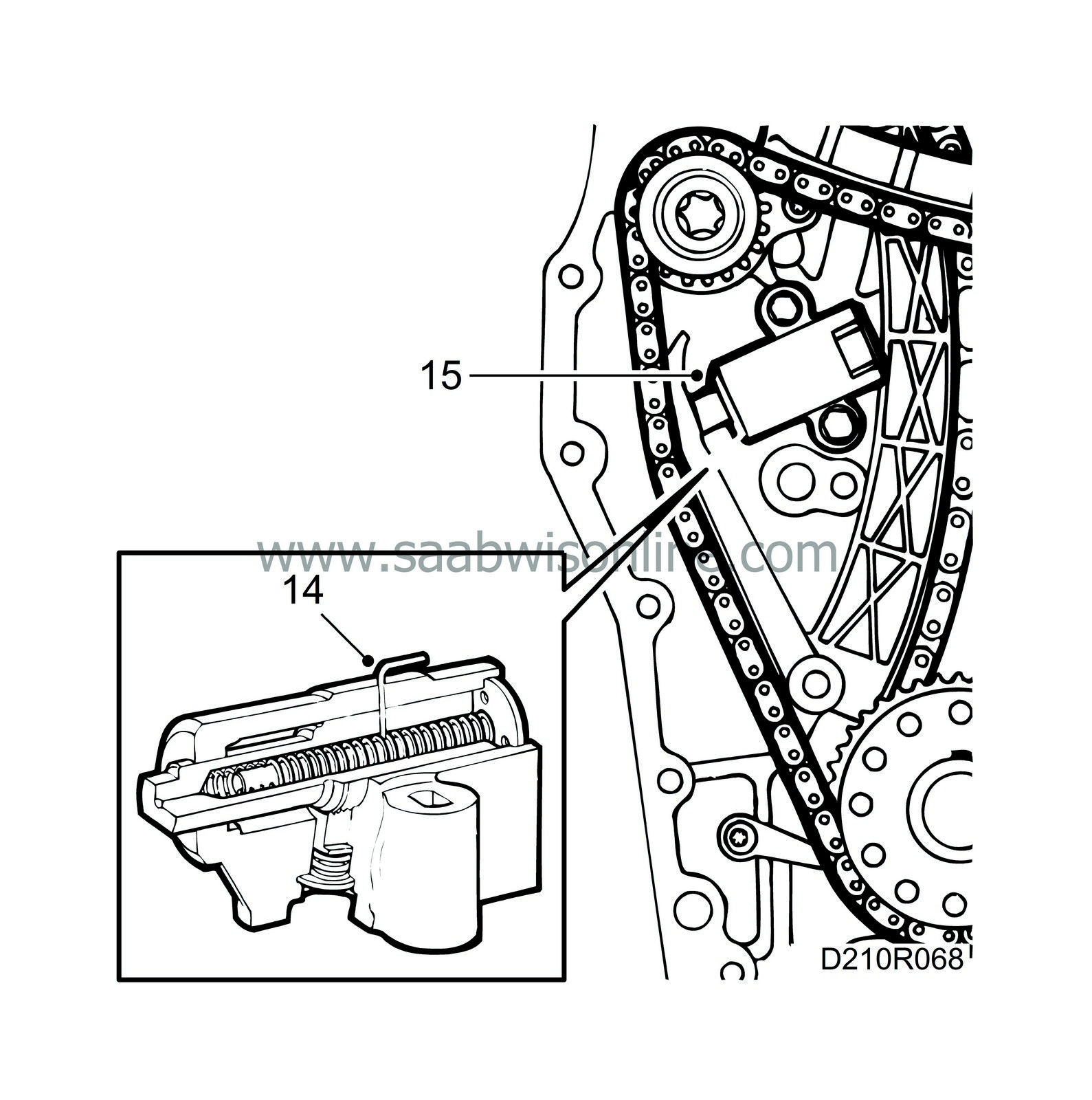
14.
|
Cock the balancer shaft chain tensioner and insert a paper clip or similar object through the hole in the cylinder to prevent triggering of the tensioner. Before this, check that the plunger is turned to the position where it really is pressed out by the spring.
|
|
15.
|
Fit the chain tensioner.
Tightening torque: 10 Nm (7 lbf ft)
 Warning
|
|
It is extremely important for the function that the correct torque is applied when fitting.
|
|
|
|
|
|
|
|
16.
|
Inspect the balancer shaft chain and fit it and the idler sprocket so that the upper setting markings behind the balancer shaft sprocket and bearing housing are aligned with each other. Tauten the chain between the crankshaft and balancer shafts. Fit the idler sprocket last of all. Hold the bolt in place with your thumb, mesh the teeth of the sprocket with the chain and "roll" it into position along the chain.
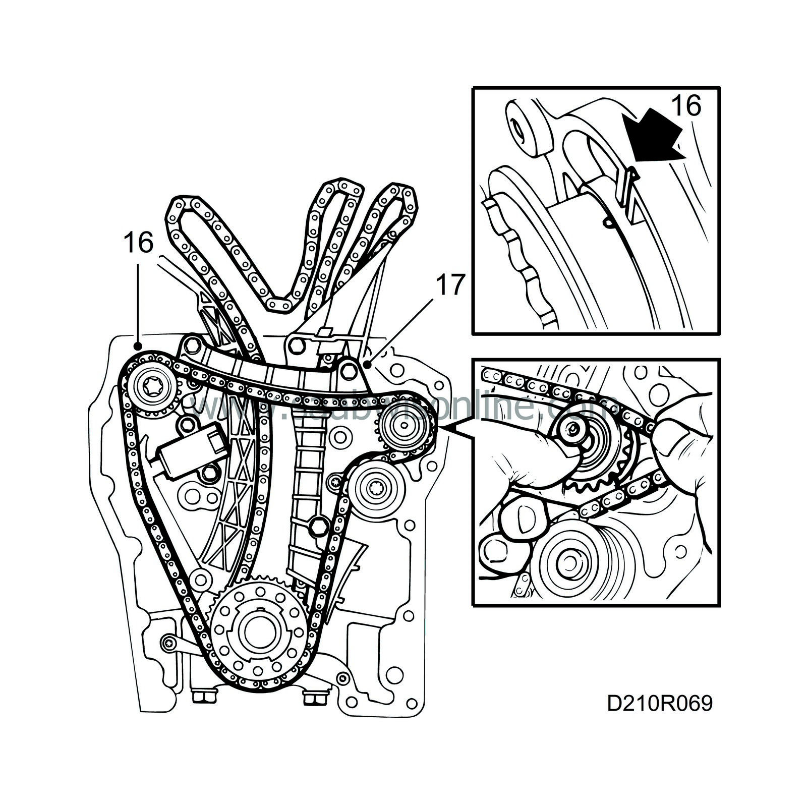
Tightening torques:
Idler sprocket, balancer shaft chain 25 Nm (18.5 lbf ft)
|
|
17.
|
Fit the top chain guide, pull out the chain slightly from the cylinder block and release the tensioner. Make sure there is a certain play by pressing in the tensioner. Rotate the crankshaft one revolution and then check that the setting is correct.
Tightening torque: 10 Nm (7 lbf ft)
|
|
18.
|
Make sure the mating face on the timing cover is completely clean. Apply a bead of flange sealant, part no. 93 21 795, approx. 1 mm wide on the timing cover. Apply the bead in the centre of the sealing surfaces.
|
|
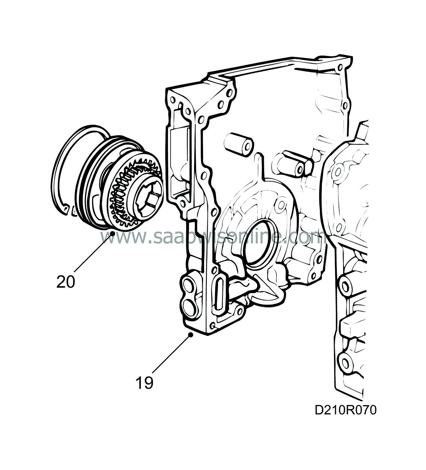
19.
|
Fit the timing cover.
Tightening torque: 22 Nm (16 lbf ft)
|
|
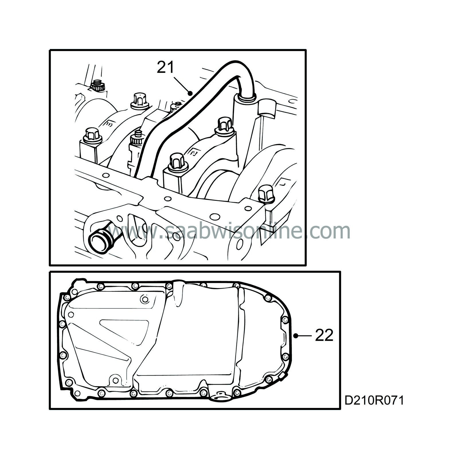
21.
|
Fit the oil pump pressure pipe and check that there are no impurities or other foreign matter in the oil sump.
|
|
22.
|
Make sure the mating surface on the oil sump is completely clean and apply an even coat of flange sealant, part no. 93 21 795, turn over the engine and fit the oil sump.
Tightening torque: 22 Nm (16 lbf ft)
|
|
23.
|
Turn the engine in the stand, rotate the crankshaft 45° and fit the cylinder head with a new gasket. Make sure it is correctly seated on the guide sleeves and that the chain runs freely.
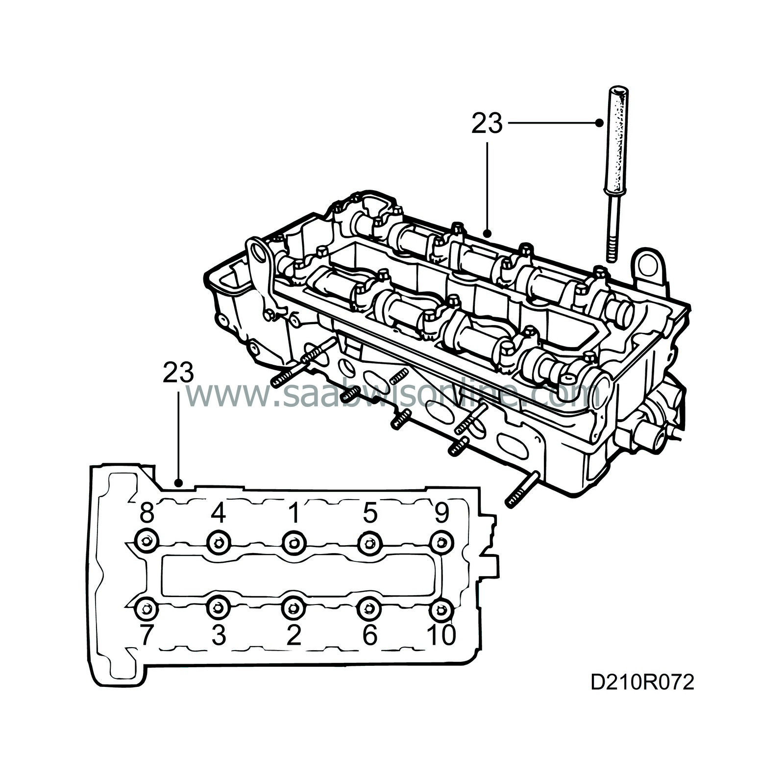
Tighten the bolts in the order shown in the illustration.
Tighten in three stages:
Stage I: 40 Nm (29.5 lbf ft)
Stage II: 60 Nm (44.3 lbf ft)
Stage III: A further 90°
|
|
24.
|
Fit the two bolts between the timing cover and cylinder head.
Tightening torque: 24 Nm (18 lbf ft)
|
|
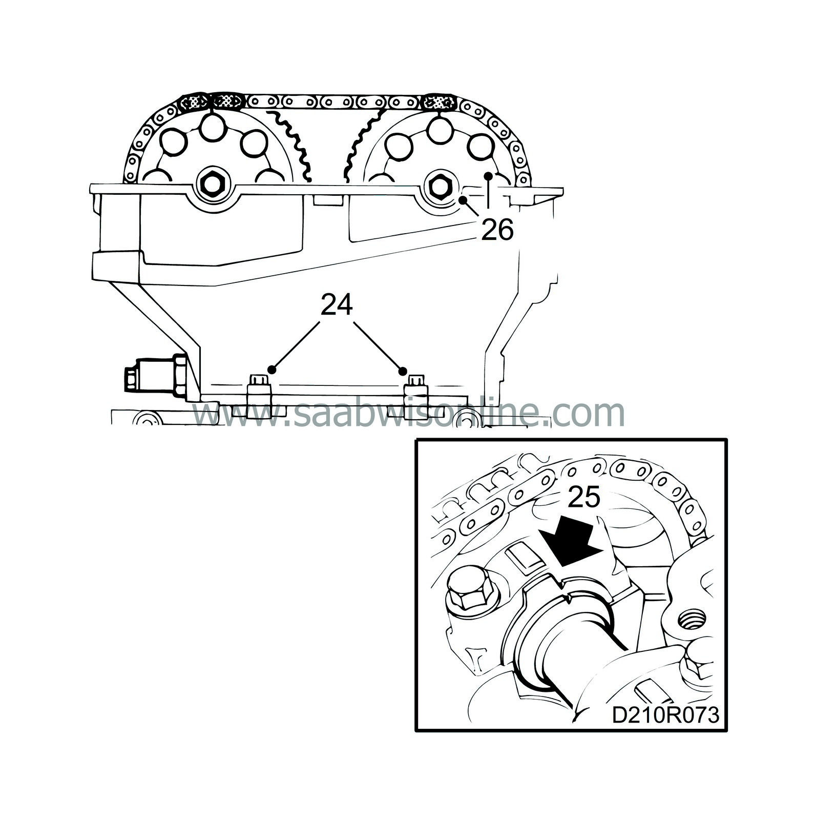
25.
|
Make sure the camshafts are aligned with their setting markings and return the crankshaft to its 0-marking.
|
|
26.
|
Fit the camshaft sprockets and chain. Start with the intake camshaft.
|
Note
|
|
Do not tighten the bolts.
|
|
|
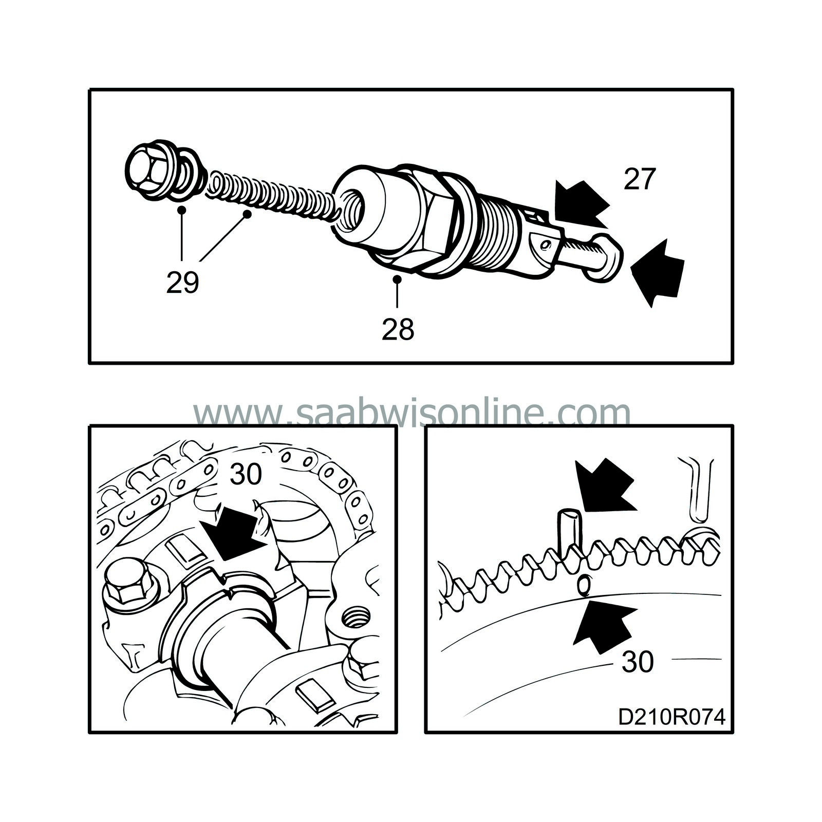
27.
|
Prepare the chain tensioner for mounting by pressing down the catch and pressing in the chain tensioner.
|
|
28.
|
Fit the chain tensioner with a 27 mm socket.
Tightening torque: 63 Nm (47 lbf ft)
|
|
29.
|
Fit the chain tensioner plug with push rod and spring.
Tightening torque: 22.5 Nm (17 lbf ft)
|
|
30.
|
Make sure the chain is positioned correctly on the chain guards. Rotate the crankshaft two revolutions and check the setting of the flywheel and camshafts.
|
|
31.
|
Tighten the camshaft sprocket bolts.
Tightening torque: 63 Nm (47 lbf ft)
|
|
32.
|
Clean the sealing surface of the camshaft cover with benzine.
|
|
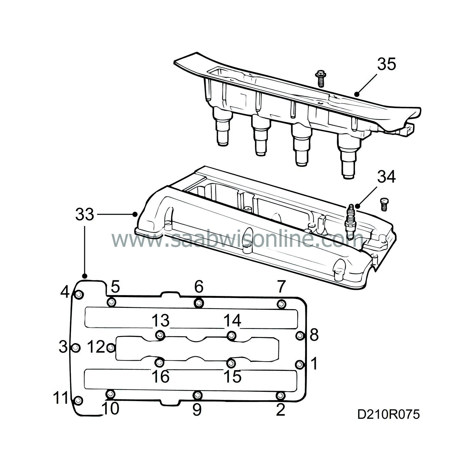
33.
|
Apply soap to the opening in the camshaft cover and fit the cover, starting at the opening. Then tighten the bolt located furthest to the front at the timing chain end. Continue all the way round the outside and inside.
Tightening torque: 15 Nm (11 lbf ft)
|
|
34.
|
Fit the spark plugs.
Tightening torque: 28 Nm (21 lbf ft)
|
|
35.
|
Fit the ignition discharge module (turbo), or alternatively the ignition leads and cover.
Tightening torques:
Ignition discharge module: 11 Nm (8 lbf ft)
Cover: 4 Nm (3 lbf ft)
|
|
37.
|
Fit the exhaust manifold with a new gasket. If it is a two-part exhaust manifold, fit the outer part first. Make sure the connecting surfaces to the front pipe are level with each other.
Tightening torques:
Lock nuts: 17.5 Nm (13 lbf ft)
Lock nuts (turbo): 24 Nm (18 lbf ft)
|
Note
|
|
There are sleeves on the outer studs only.
|
|
|
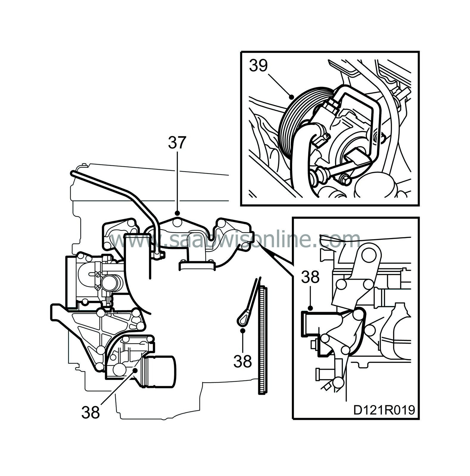
38.
|
Fit the adapter housing and oil filter. Fit the crankshaft position sensor and thermostat housing cover.
|
|
39.
|
Fit the power steering pump and bracket.
|
|
40.
|
Fit the turbocharger.
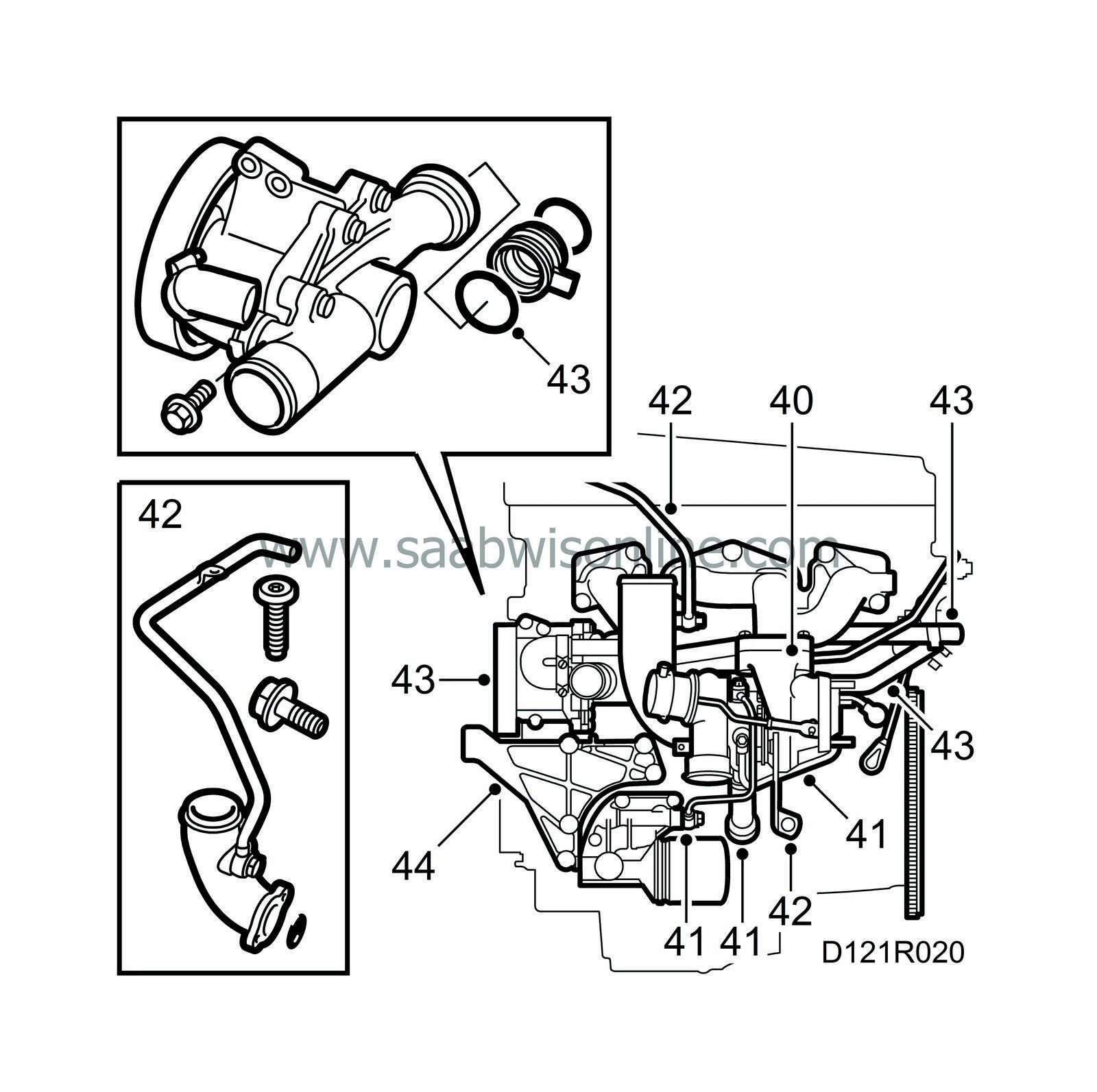
Tightening torques:
Stud screws: 22 Nm (16 lbf ft)
Lock nuts: 25 Nm (19 lbf ft)
|
|
41.
|
Connect the water and oil pipes (turbo).
Tightening torques:
Water pipe: 25 Nm (19 lbf ft)
Oil pipe, in: 25 Nm (19 lbf ft)
Oil pipe, out: 22 Nm (16 lbf ft)
|
|
42.
|
Fit the turbocharger stay and the pipe for the crankcase ventilation together with the intake manifold (turbo). Be careful with the O-ring!
Tightening torques:
Turbo, stay to block: 22 Nm (16 lbf ft)
Turbo/intake manifold: 8 Nm (6 lbf ft)
Crankcase ventilation pipe: 24 Nm (18 lbf ft)
Pipe clamp: 9.5 Nm (7 lbf ft)
|
|
43.
|
Lubricate the O-rings with acid-free Vaseline and fit the water pump and the water pipes from the expansion tank and heat exchanger. Fit the clips for the crankshaft position sensor at the same time.
|
|
44.
|
Fit the bracket for the engine mounting.
|
|
45.
|
Position the intake manifold gasket using bayonet pins, part no. 83 94 736, and fit the intake manifold.
Tightening torque: 24 Nm (18 lbf ft)
|
|
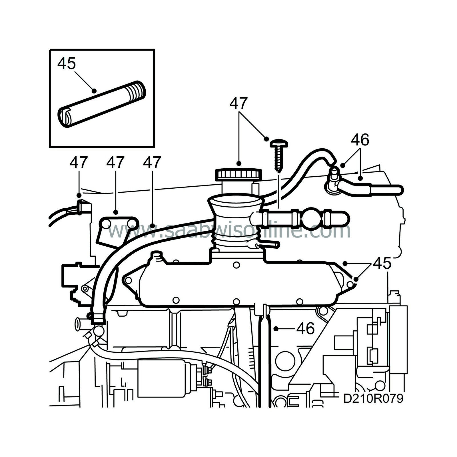
46.
|
Fit the intake manifold stay and connect the positive crankcase ventilation nipple.
Tightening torque: 24 Nm (18 lbf ft)
|
|
47.
|
Connect the cables to the ignition discharge module (turbo), the temperature sensor and the hoses to the throttle body. Fit the oil filler pipe bracket.
Tightening torques:
Upper mounting: 10 Nm (7 lbf ft)
Lower mounting: 22 Nm (16 lbf ft)
|
|
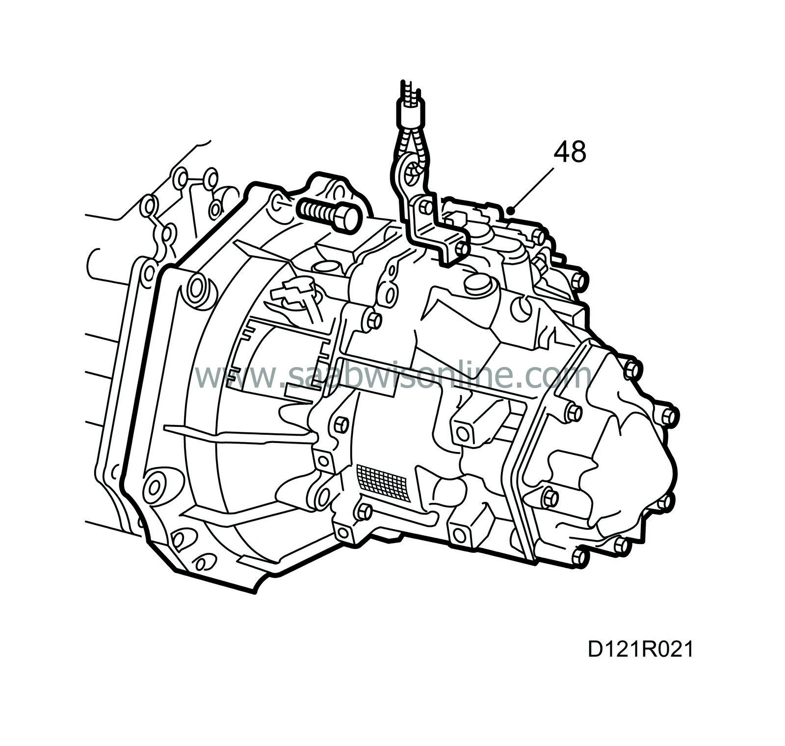
48.
|
Make sure the torque converter bottoms in the gearbox and that the lock screw is fitted (aut.). Fit the gearbox and tighten the bolts.
|
|
49.
|
Tighten the bolts on the torque converter (aut.). Use thread locking adhesive, part no. 74 96 292, on the bolts.
Tightening torque: 60 Nm (44 lbf ft)
|
|
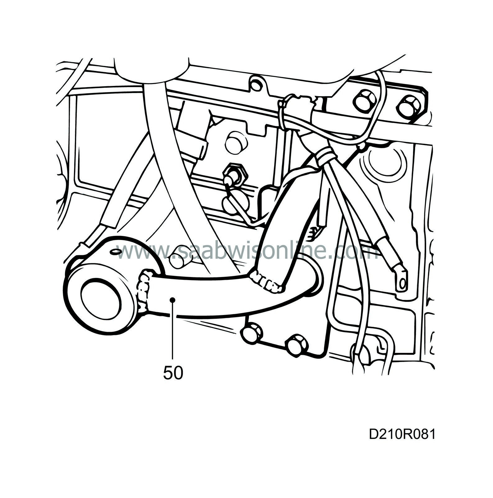
50.
|
Connect a lifting sling and lift the engine away from the stand. Remove the fixture and place the engine on the lifting trolley.
|
|
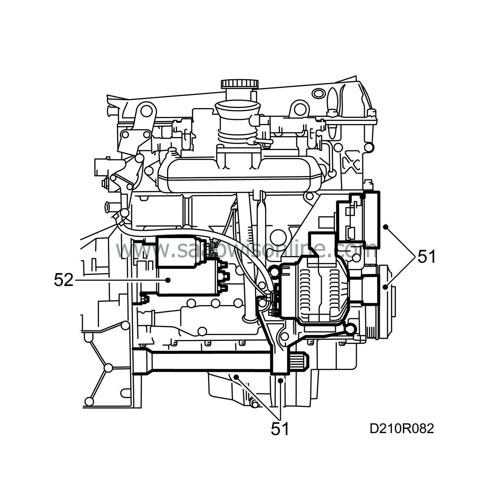
51.
|
Fit the bearing bracket with pipe and the inboard drive shaft. Fit and connect the generator and fit the belt tensioner.
|
|
52.
|
Fit the starter motor and connect the cables. Make sure the oil drain plug is tight. The power train is now ready for fitting in the car.
|


