Check values, control module connections, DICE
|
|
Check values, control module connections, DICE
|
Values and directions for measuring signals and levels in DICE can be found on the following pages.
|
•
|
Note the measuring conditions, use common sense when considering the measurement results.
|
|
•
|
The values given apply with the ignition key in the ON position unless otherwise indicated.
|
|
•
|
First check that the control module is supplied with power and that it is grounded.
|
|
•
|
Then check all the sensor inputs and signals from other systems.
|
|
•
|
Finally, check the control module outputs. Remember that the measured values will not indicate if the switch device is functional.
|
|
•
|
If any measured value is incorrect, use the wiring diagram to diagnose which leads, connections or components that should be checked further.
|
|
•
|
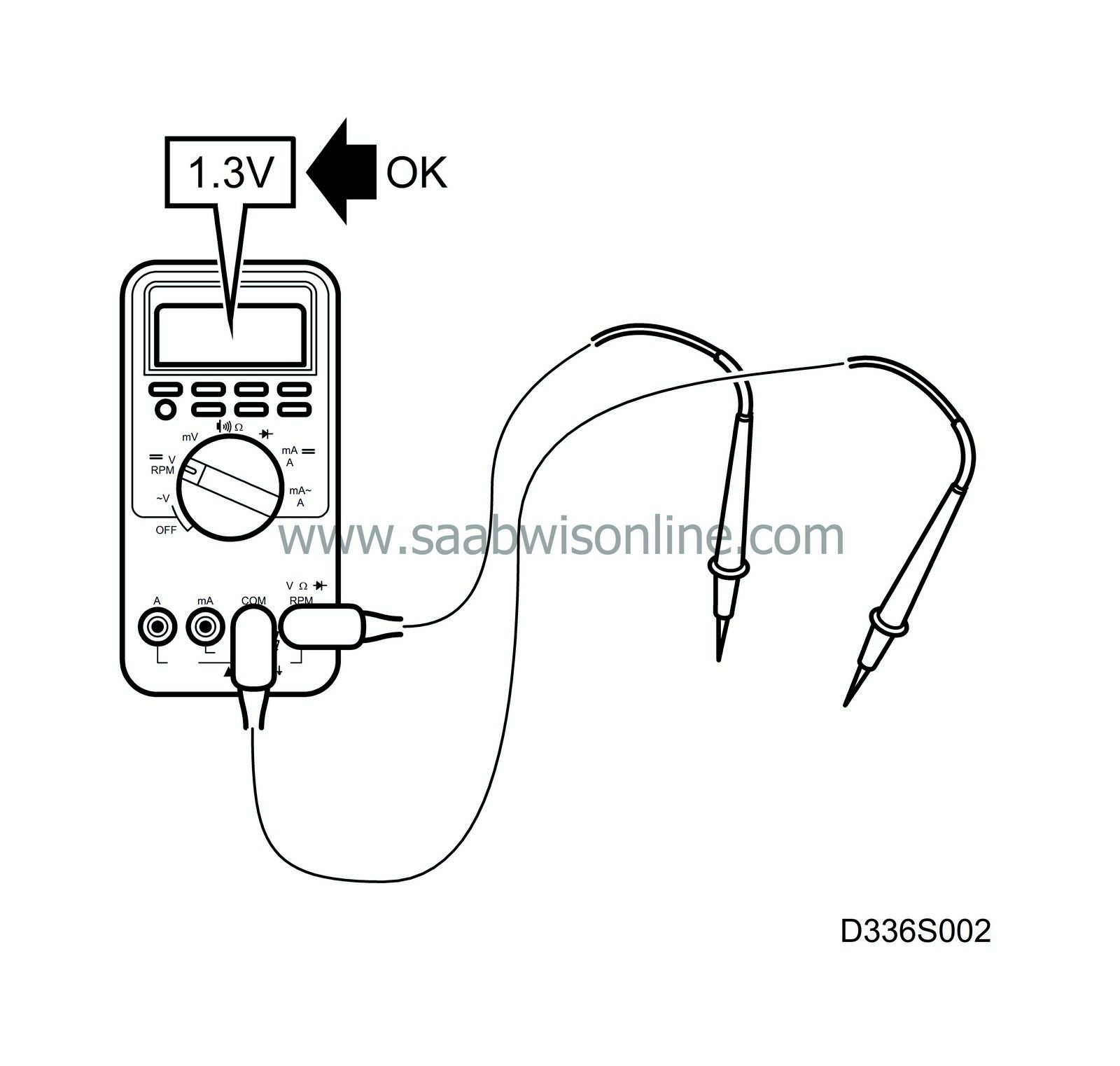
Given values refer to calibrated Fluke 88/97.
|
|
•
|
The measured values %(+) and ms(+) show the pulse ratio and pulse duration of the signal. A test instrument with pulse ratio and pulse duration measuring capacity must be used. The sign (+) indicates positive trigger pulse, TRIG+.
|
> = greater than
< = less than
»
= approximately equal to
∼ = alternating current
(LP: LOGIC PROBE P = select pulse; p = visible pulses)
For other measured values and control module connections, refer to group 03, DICE

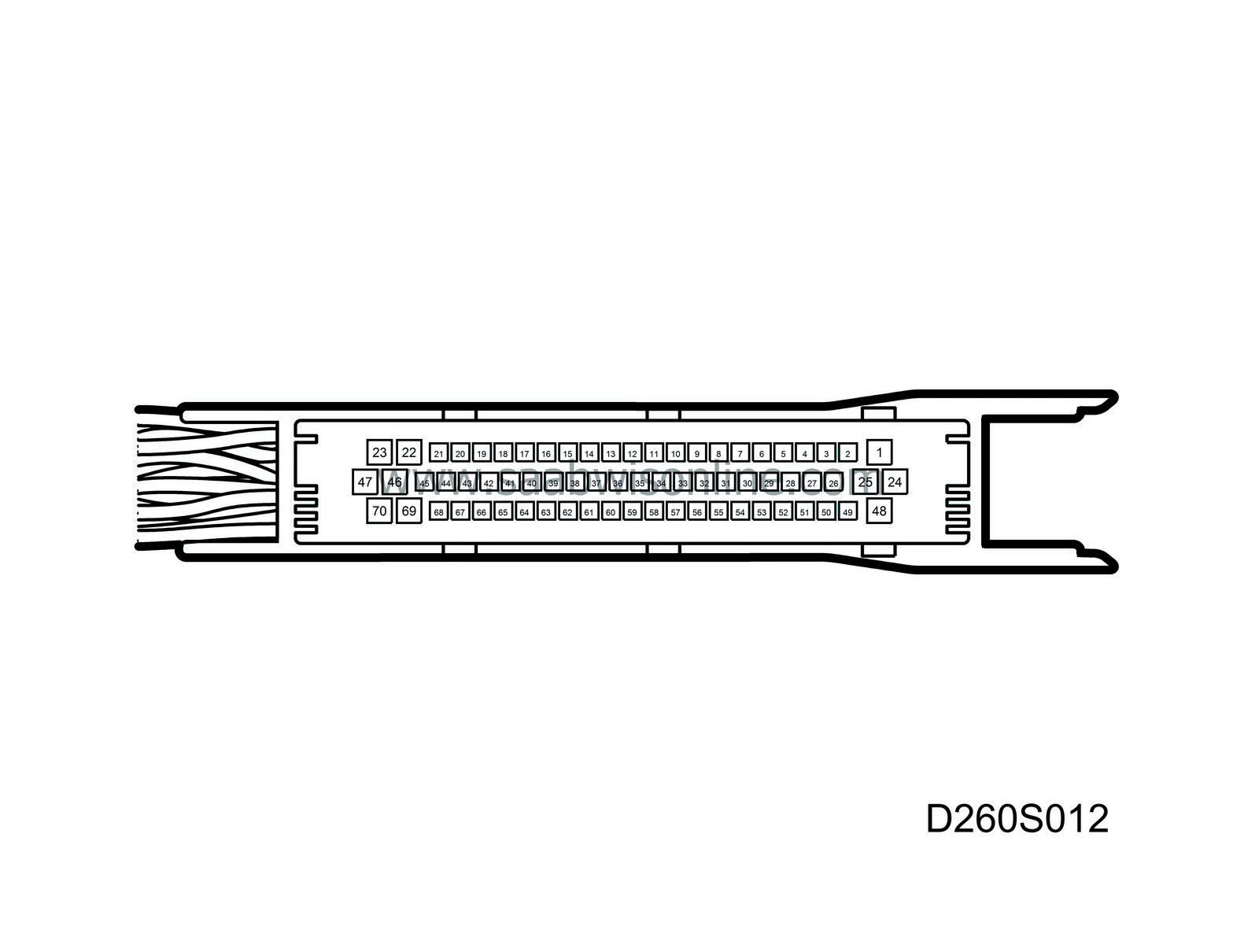
Pin no.
|
Lead colour
|
Component/function
|
In/out
|
Measuring condition
|
Measure between
|
Value
|
See
|
35
|
BN/RD
|
Radiator fan low speed,
relay.
|
Out
|
Activate function with diagnostics tool.
|
26-35
|
B+
|
Radiator fan
|
53
|
BN/GY
|
Radiator fan high speed,
relay.
|
Out
|
Activate function with diagnostics tool.
|
26-53
|
B+
|
Radiator fan
|


