(291-2217 utg. 3) Replacement of check valve and banjo screw to remedy blue smoke
|
MODIFICATION INSTRUCTION
|
|
Bulletin Nbr:
|
291-2217 utg. 3
|
|
Date:
...........
|
Augusti 2000
|
|
Market:
|
US, CA, JP
|
|
|
Replacement of check valve and banjo screw to remedy blue smoke
|
|
Emissions-related campaign 10719
|
Cars in stock must be remedied before delivery.
A personal communication must be sent to the owners of cars already delivered requesting them to get in touch with the nearest Saab garage as soon as possible to have the fault rectified.
Saab 9-3 with B205 or B235 engines M99-M00 up to and including VIN:
Y2017062 (3D/5D excluding Viggen)
Y7005097 (Viggen 3D/5D and all CV)
Some cars produce unwanted blue smoke. There are two possible reasons:
|
•
|
The check valve for the crankcase ventilation can stick, which means that engine oil can be forced out into the exhaust pipe, resulting in blue smoke.
|
|
•
|
The flow of coolant through the turbo unit may be reduced, which results in the temperature becoming so high that the engine oil crystallizes (builds carbon deposits) around the turbine-side bearing. Over time these deposits reduce the oil flow through the bearing, which means that engine oil is forced past the turbine shaft seal and out into the exhaust pipe, resulting in blue smoke.
|
This MI describes the procedure for preventing blue smoke and damage to the turbo unit.
51 25 406 Banjo screw
81 24 141 Gasket (x2)
93 99 973 Hose with check valve
79 71 864 Cable tie
16 - 30 04 223 Electronics cleaner (sufficient for 10 cars)
Examine boxes B5 and C5 on the modification identity plate before proceeding. Are the boxes marked?
|
•
|
Both B5 and C5 are marked.
The car has been rectified.
|
|
•
|
B5 is marked but not C5.
Carry out steps 1, 3 (but only detach the vacuum hose from the camshaft cover), 6, 7, 8 and 15 below.
|
|
•
|
Neither B5 or C5 is marked.
Proceed as follows:
|
B205L M99-M00 up to VIN Y2013566 (3D/5D excluding Viggen) and Y7003737 (CV excluding Viggen):
Perform all steps.
B205L M00 within VIN interval Y2013567-Y2017062 (3D/5D excluding Viggen) and Y7003738-Y7005097 (CV excluding Viggen):
Perform steps 1-15 only.
B205R/235R:
Perform steps 1-15 only.
|
1.
|
Remove the engine cover.
|
|
2.
|
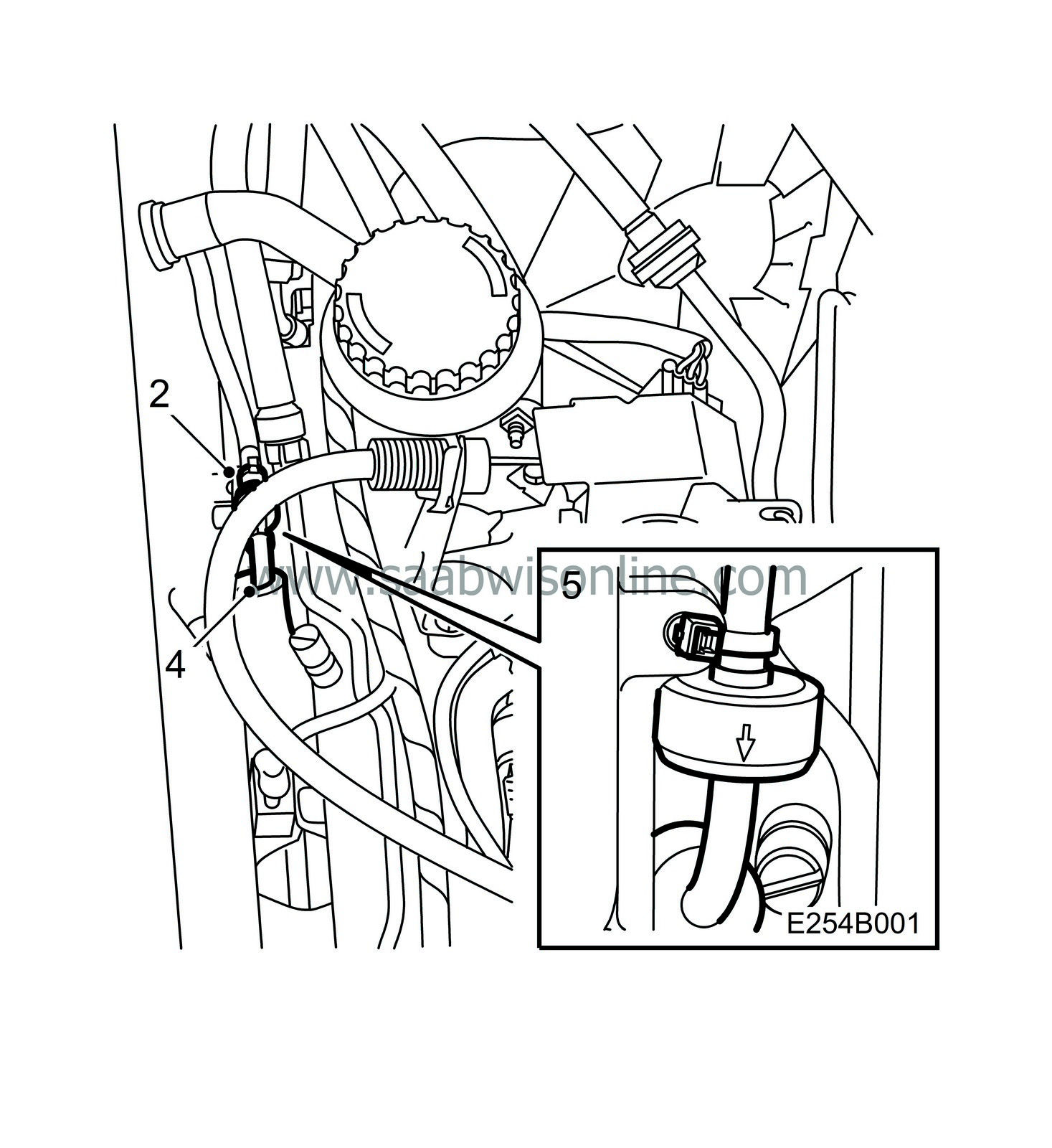
Cut off the cable tie securing the check valve to the camshaft cover.
|
|
3.
|
Pull the check valve vacuum hose off the camshaft cover and the throttle body.
|
|
4.
|
Transfer the insulation hose from the old hose to the new.
|
|
5.
|
Connect the new hose to the throttle body.
|
Important
|
|
The check valve must be turned so that the flow is directed away from the camshaft cover towards the throttle body, see the arrow on the check valve.
|
|
|
Fasten the check valve to the camshaft cover using a cable tie.
|
|
6.
|
Remove the crankcase ventilation hose from the nipple on the camshaft cover and remove the nipple from the cover.
|
|
7.
|
Clean the nipple for the check valve vacuum hose with a 2 mm drill bit. Flush with compressed air to clean.
|
|
8.
|
Fit the nipple to the camshaft cover and connect the hoses to the nipple.
|
|
9.
|
Check that the ignition key is in the OFF position.
|
|
10.
|
Remove the bolt securing the turbocharger delivery pipe mounting to the engine and the hose clip from the pipe attachment on the throttle body.
|
|
11.
|
Remove the turbocharger delivery pipe and move it to one side. Keep the O-ring.
|
|
12.
|
Turn the throttle disc until open and clean the inside of the throttle body, especially around the sealing surfaces of the throttle disc. Use a lint-free cloth dampened with electronics cleaner (part no. 16 - 30 04 223).
|
|
13.
|
Grease the O-ring with acid-free vaseline and fit the turbocharger delivery pipe to the throttle body.
|
|
14.
|
Fit the bolt securing the turbocharger delivery pipe mounting to the engine and the hose clip to the pipe attachment on the throttle body.
|
|
15.
|
Fit the engine cover.
|
|
16.
|
Open the coolant expansion tank cap to release the overpressure in the cooling system. Shut the cap.
 Warning
|
|
Take care if the car is warm. The coolant is hot and there is also a risk of burning yourself on the manifold.
|
|
|
|
|
|
|
|
17.
|
Place a receptacle under the car.
|
|
18.
|
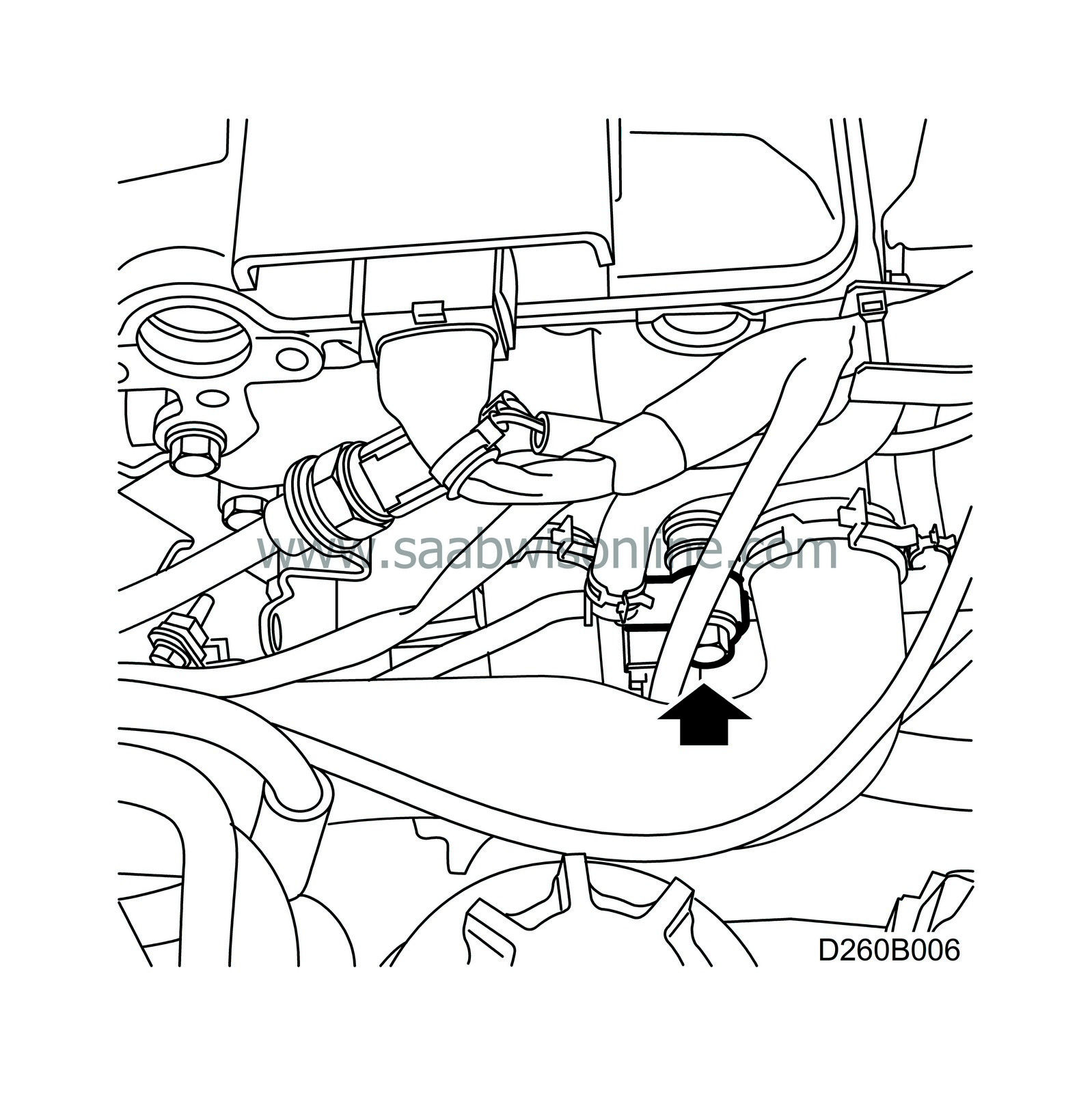
Using a fixed spanner to hold the coolant pipe nipple in place on the cylinder head, detach the coolant pipe from the cylinder head, see illustration, and the pressure sensor mounting.
|
|
19.
|
Check that the coolant pipe nipple on the cylinder head is tightened, and fit the coolant pipe with a new banjo screw and new gaskets in the cylinder head, see illustration. Fasten the pipe to the pressure sensor mounting.
|
Important
|
|
Banjo screw 51 25 406 must not be fitted anywhere else on the cooling system other than on the cylinder head connection.
|
|
|
Tightening torque:
Nipple in cylinder head 35 Nm (25.8 lbf ft)
Banjo screw, cylinder head 25 Nm (18.4 lbf ft)
|
|
20.
|
Top up the coolant if necessary.
|
|
Marking the modification identity plate
|
On completion of the necessary procedure, boxes B5 and C5 of the modification identity plate must be marked. If the work was carried out by the importer, mark the boxes with a "7". If done by a dealer, mark with an "8".
|
Warranty/Time information
|
See separate information.


