PRE-RELEASE
Steering column assembly
| Steering column assembly |
| To remove |
|
|||||||
See Safety and handling directions .
|
|||||||
|
|||||||
| Important | ||
|
Ensure the wheels are pointing straight ahead before dismantling begins. |
||
| 1. |
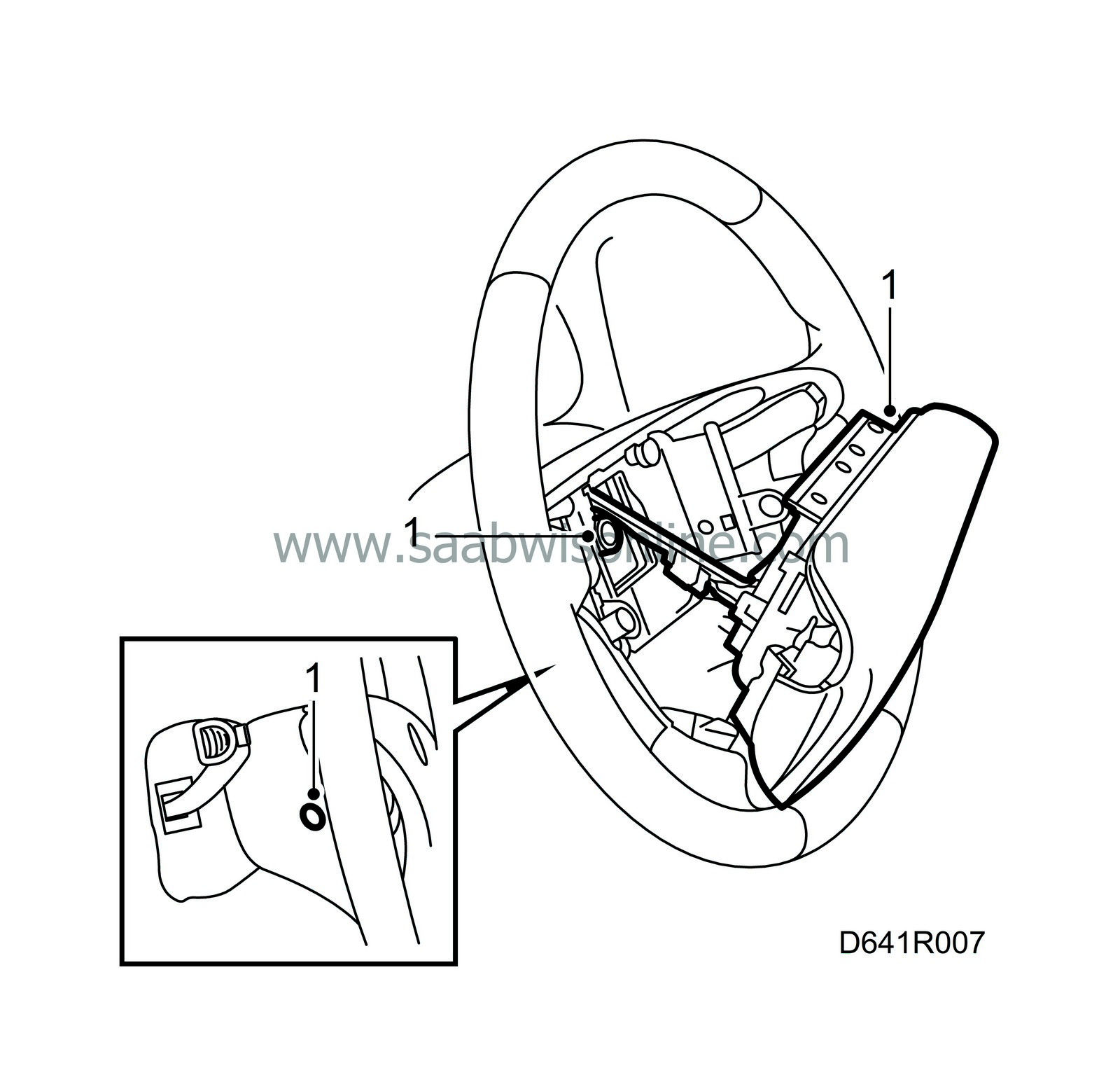
Remove the steering wheel.
|
|
| • |
Remove the airbag from the steering wheel, 2 plugs and screws.
|
| • |
Lift out the airbag module and unplug the connector.
|
||||||||||
| • |
Loosen the steering wheel nut leaving it on its last threads and pull the steering wheel up to the nut. Then remove the nut and carefully lift off the steering wheel.
|
| 2. |
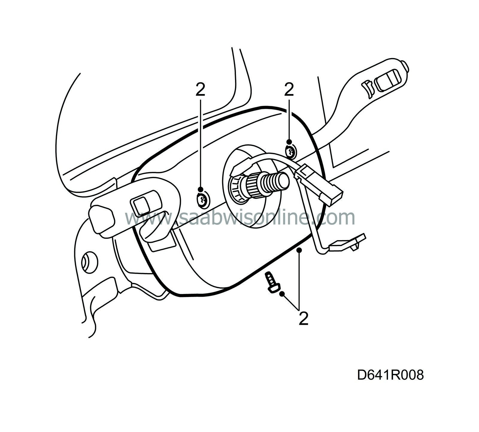
Remove the top and bottom steering column covers, three screws.
|
|||||||
| 3. |
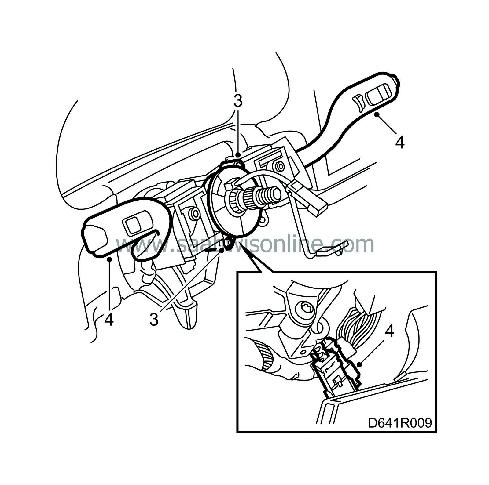
Remove the two contact roller screws and unplug the connectors.
|
|
| 4. |
Remove switches and the direction indicator and wiper stalk switches. Remove the securing cable from the bearing housing.
|
|
| 5. |
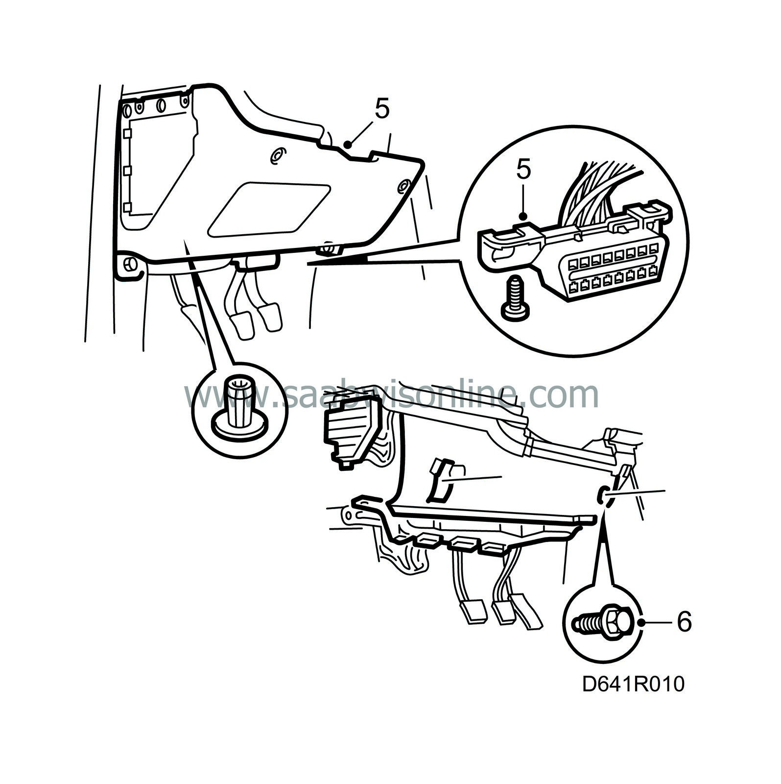
Remove the lower dashboard panel.
|
|
| 6. |
LHD:
Remove the two knee member bolts and then the knee member.
|
|
| 7. |
RHD:
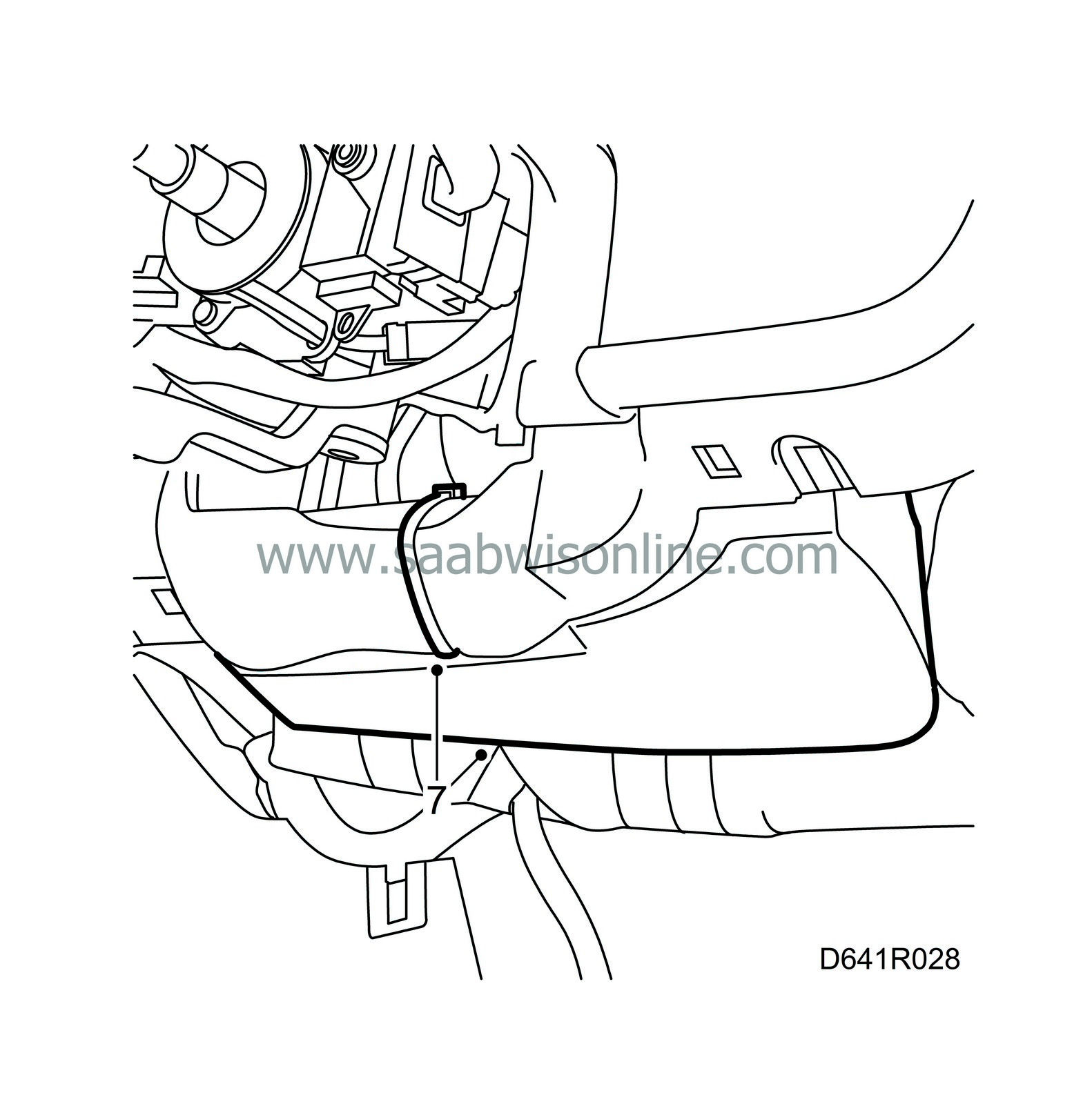
Cut off the cable tie and remove the knee shield.
|
|
| 8. |
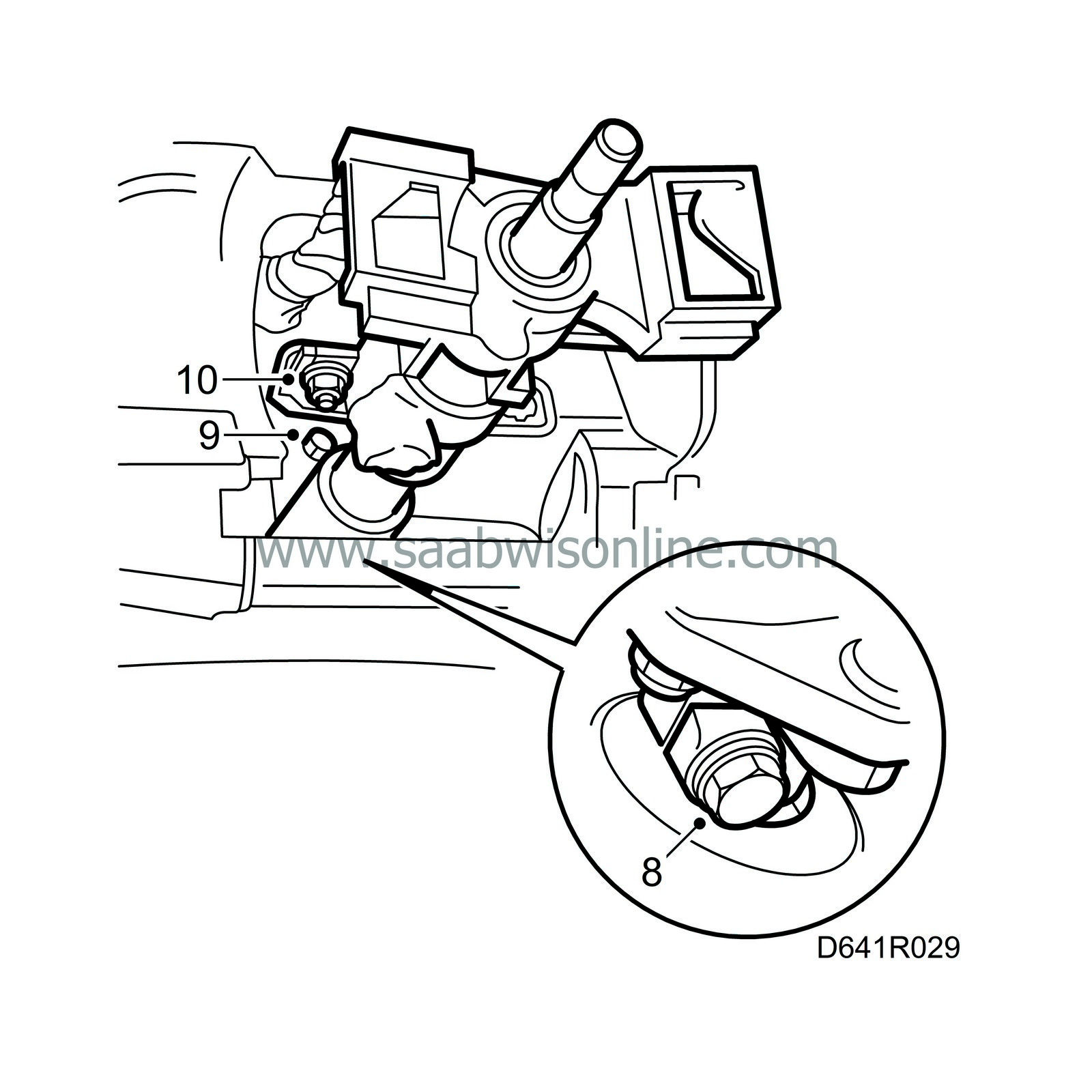
Remove the steering shaft universal joint and lift the joint off the pinion shaft.
|
|
| 9. |
Remove the lower steering column assembly bolt above the air duct.
|
|
| 10. |
Remove the two upper steering column assembly nuts under the instruments.
|
|
| 11. |
Remove the steering column assembly.
|
|
| To fit |
| 1. |
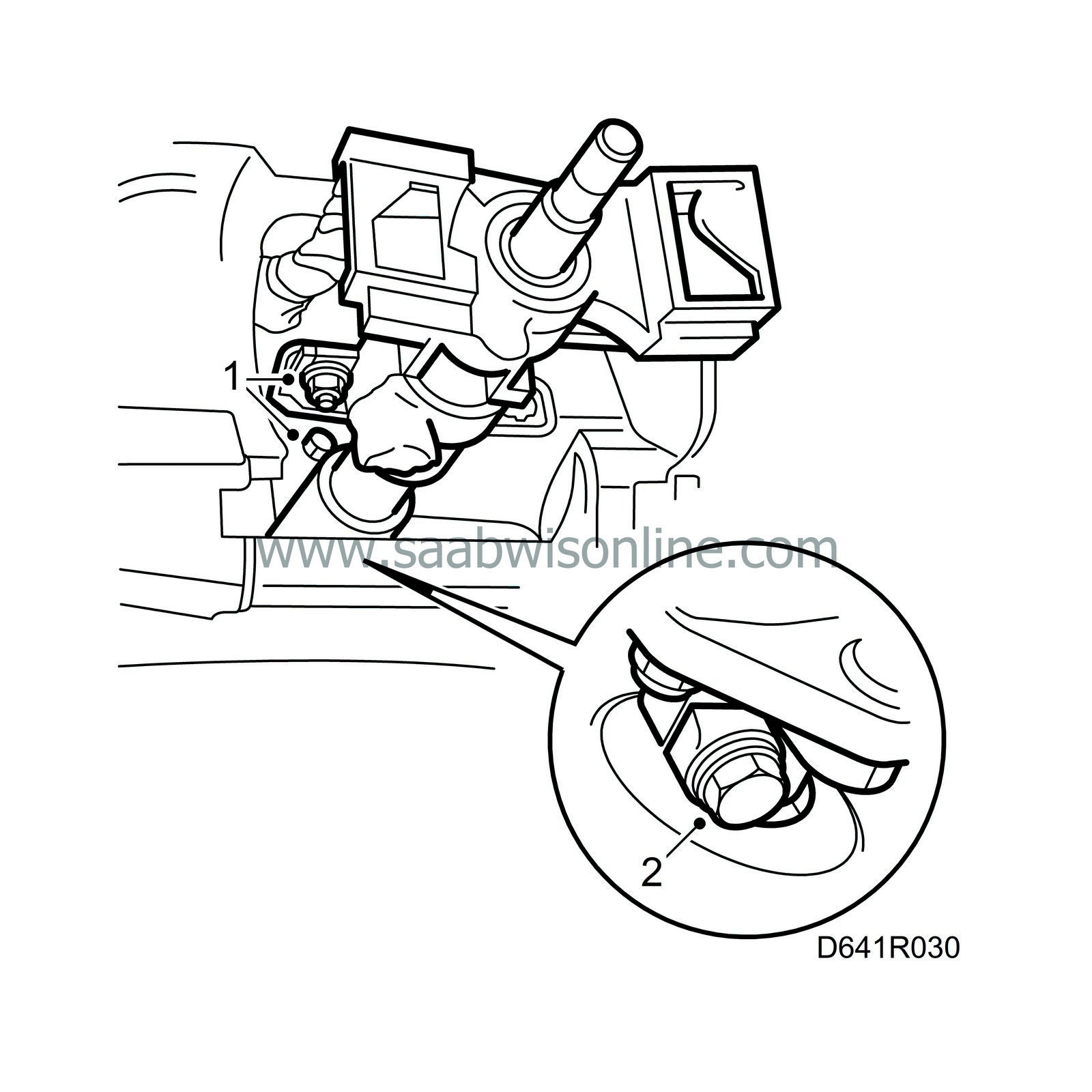
Put the steering column assembly in place and screw home the two top nuts and the lower bolt.
|
||||||||||
| 2. |
Fit the steering shaft joint to the pinion shaft.
Tightening torque: 24 Nm (18 lbf ft) |
|
| 3. |
Adjust the steering wheel to its lowest position and secure with the adjustment lever.
|
||||||||||
| 4. |
Tighten the two upper nuts.
Tightening torque: 24 Nm (18 lbf ft) 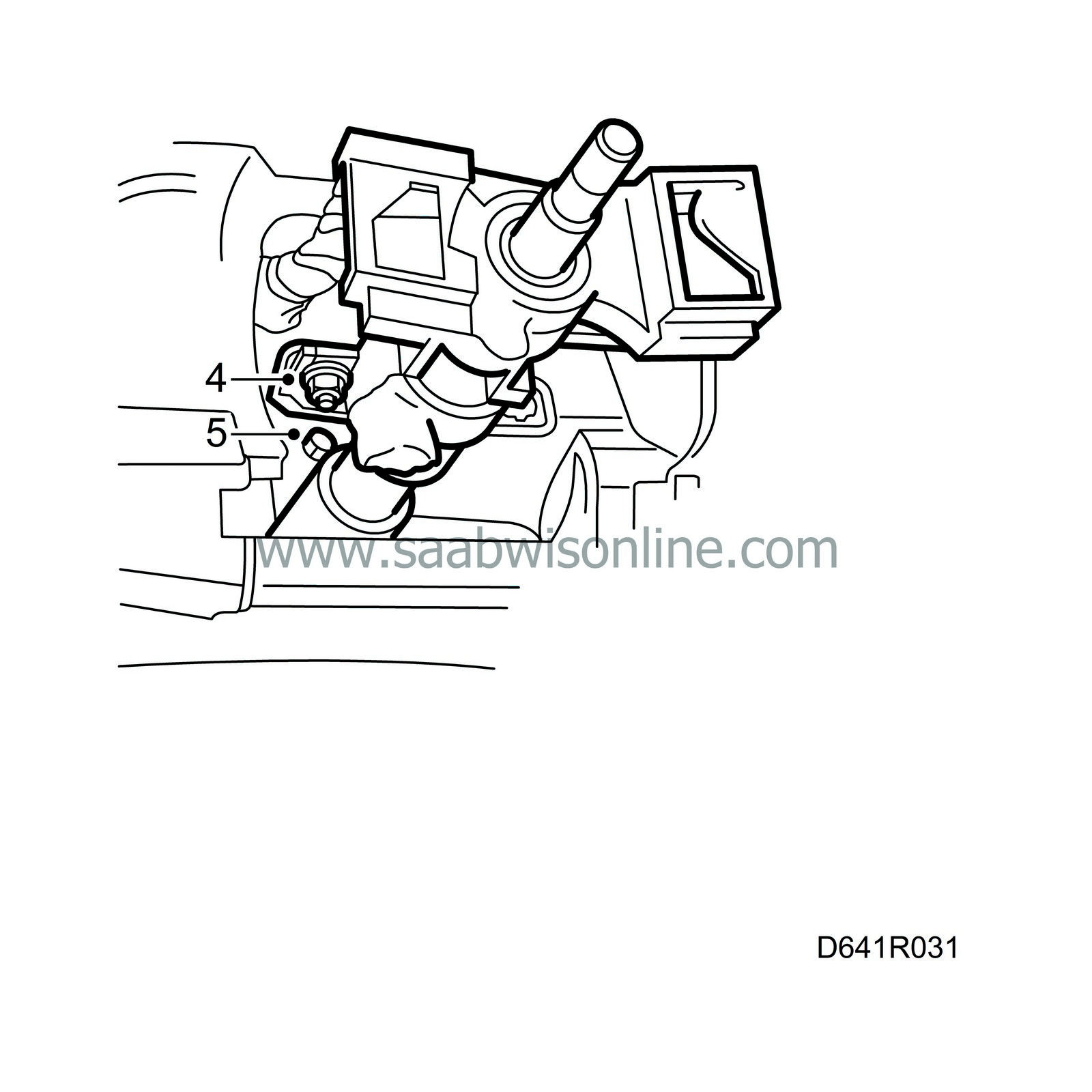
|
|
| 5. |
Tighten the lower bolt.
Tightening torque: 24 Nm (18 lbf ft) |
|
| 6. |
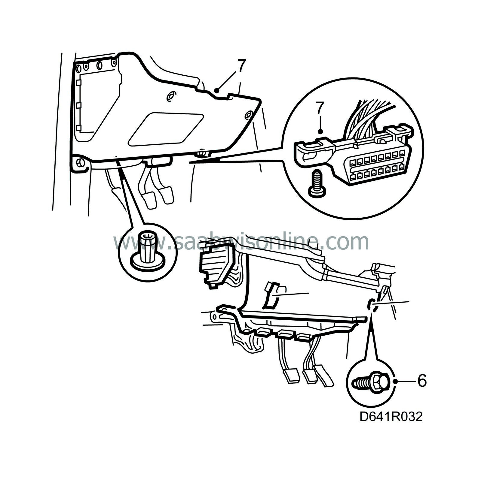
Fit the lower dashboard panel and the knee member.
|
|
| 7. |
LHD:
Fit the lower dashboard panel.
|
|
| 8. |
RHD:
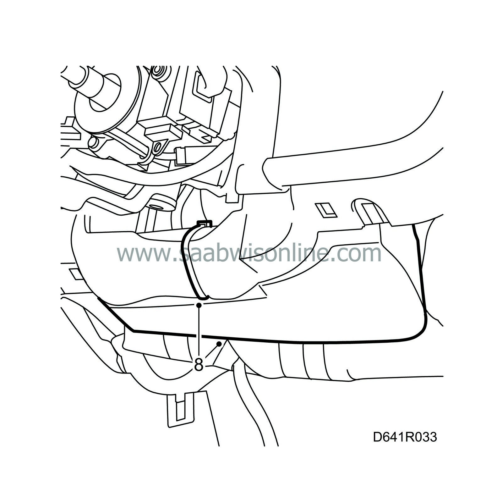
Fit the knee shield with a cable tie.
|
|
| 9. |
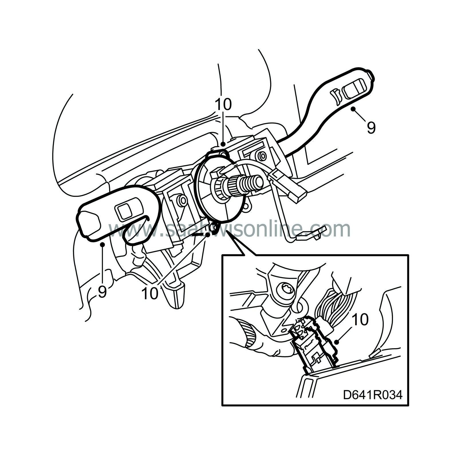
Fit the switches and securing cable.
|
|
| 10. |
Fit the two screws for the contact roller. Plug in the connectors.
Fit the top and bottom steering column covers. Adjust the contact roller centre position.
|
|||||||||||||||
| 10.a. |
Make sure the wheels are pointing straight ahead.
|
| 10.b. |
Rotate the contact roller
clockwise
until a steady resistance is felt.
|
| 10.c. |
Rotate the contact roller 2 turns in the opposite direction plus whatever is necessary for the electrical leads to stand straight up (“12 o'clock“).
|
| 11. |
Fit the steering wheel and tighten the centre nut.
Tightening torque: 38 Nm (28 lbf ft) 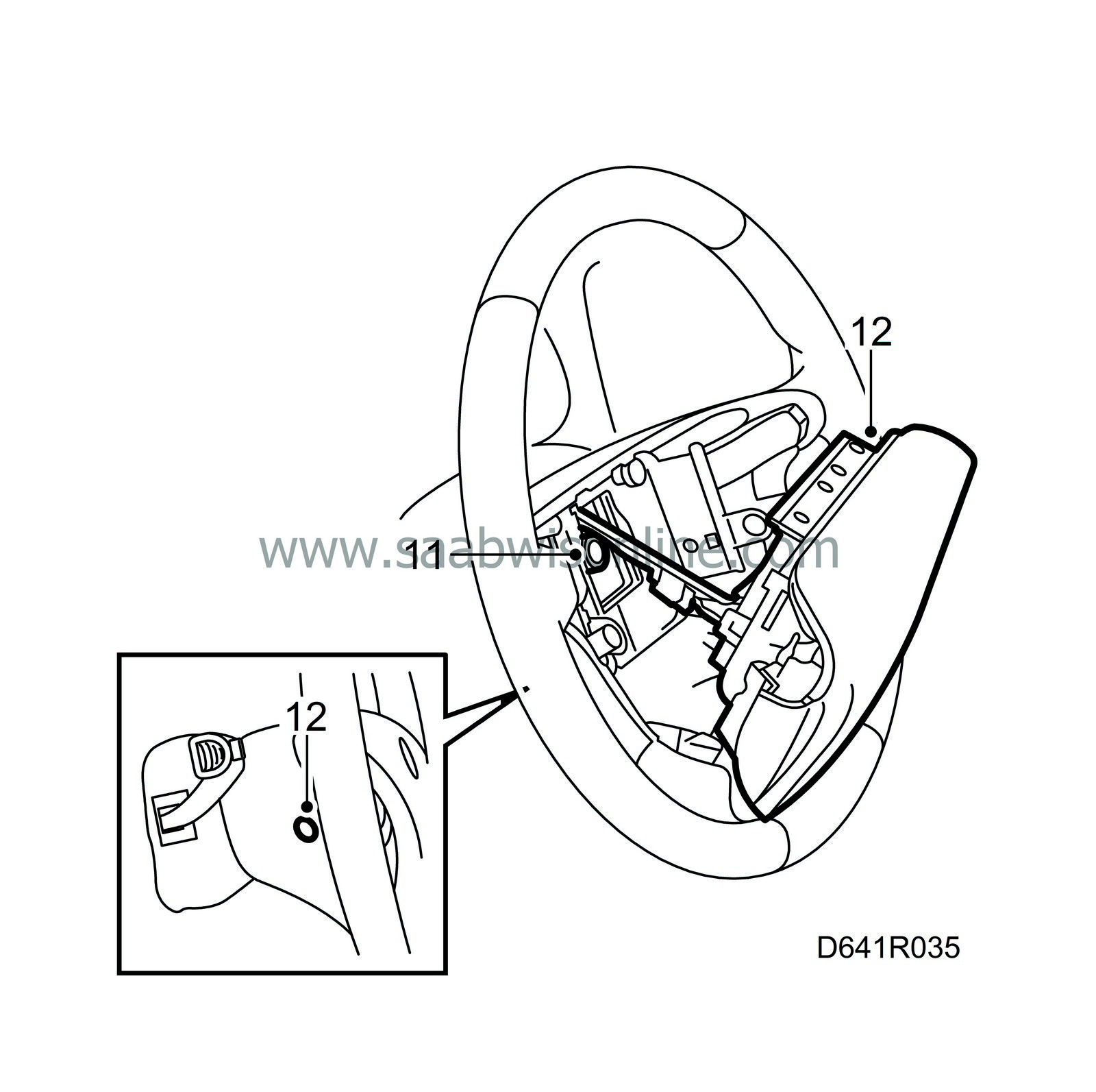
|
|
| 12. |
Plug in the connectors and fit the airbag module in the steering wheel with two screws and plugs.
|
|

 Warning

