Poor driveability, impaired performance, uneven running
Symptom: Poor driveability
Impaired performance
Engine has uneven or low idling speed
Surge or hesitation upon acceleration
|
|
Poor driveability, impaired performance, uneven running
|
Fault symptom
Poor driveability
Impaired performance
Engine has uneven or low idling speed
Surge or hesitation upon acceleration
Criteria
The car may have certain fault symptoms without a diagnostic trouble code being generated. This can be due to an air leak in the induction system.
If a fault code occurs, the respective fault diagnosis should be used to start with. The method below is a complement if the fault cannot be found using normal fault diagnosis.
Procedure
|
1.
|
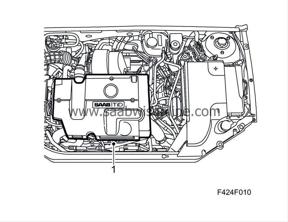
Remove the upper engine cover.
|
|
2.
|
Undo the crankcase ventilation hose clamp on the back of the camshaft cover using
30 07 739 Hose pinch-off pliers
and block the hose with a suitable plug, Ø 25mm.
|
Important
|
|
Do
not
plug the hole in the camshaft cover. The air that leaks past the pistons down in the crankshaft during test pressurising must be evacuated through this hole.
|
|
|

|
|
3.
|
Undo the intake hose from the mass air flow sensor. Fit the plug from kit 83 95 659 in the hose and then connect the wastegate to an external compressed air outlet.
|
Important
|
|
Close the pressure regulator before connecting it to the air pressure outlet.
|
|
|
|
|
4.
|
Connect Tech2, turn the ignition key to "ON" and select "Read value" for the relevant engine variant. Step forward through the list until "Charge pressure sensor" in "V" can be observed.
|
Important
|
|
When pressure increases, DTCs P0106 and P1106 will be generated due to the difference between boost pressure and atmospheric pressure. When the DTCs are generated "Boost pressure" will indicate 101 kPa, which is the default value. Boost pressure must therefore be read off directly from the voltage signal.
|
|
|
|
|
5.
|
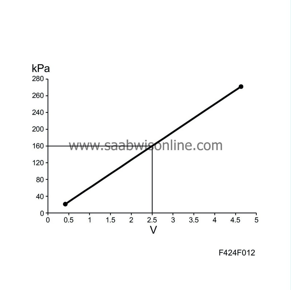
Read the voltage from the charge pressure sensor with Tech 2 and pressurise the intake system by carefully turning the wastegate until a maximum of 2.5 V is reached.
1.6V corresponds to approx. 100 kPa (atmospheric pressure)
2.5V corresponds to approx. 160 kPa (60 kPa overpressure)
|
|
6.
|
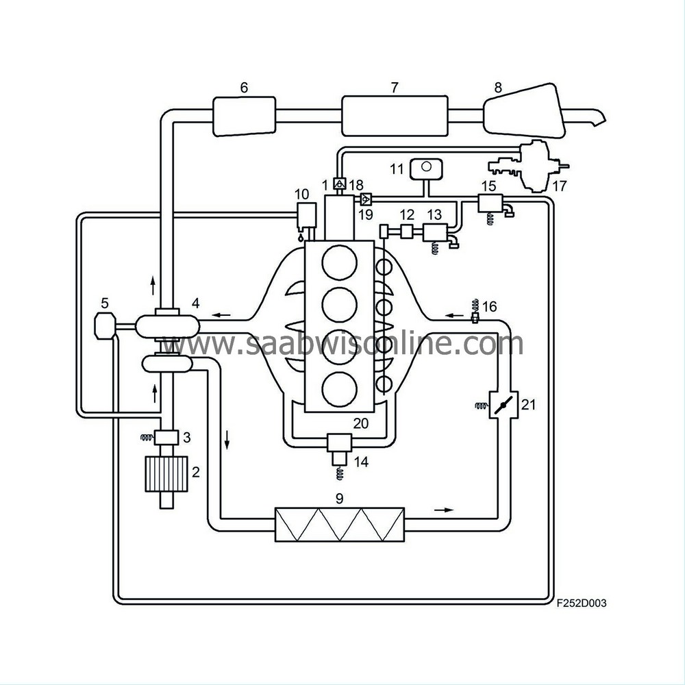
The entire induction system is thereby under pressure and leaks can be located using a leak spray or soap solution that will foam around a leak. Check all the components, hoses and connections and rectify any leaks.
|
|
|
6.3.
|
Mass air flow sensor
|
|
|
6.10.
|
Oil trap for crankcase ventilation (integrated in engine)
|
|
|
6.12.
|
Swirl throttle regulator
|
|
|
6.13.
|
Solenoid valve, swirl throttle
|
|
|
6.15.
|
Boost pressure control valve
|
|
|
6.21.
|
Cut-off valve
|
Important
|
|
Only large leaks affect the function of the engine management system. When leakage spray or soap water is used, even small leaks will be detected. Several small leaks can be grouped together and viewed as one large leak.
|
|
Individual tiny leaks need not be remedied.
|
|
|
|
|
7.
|
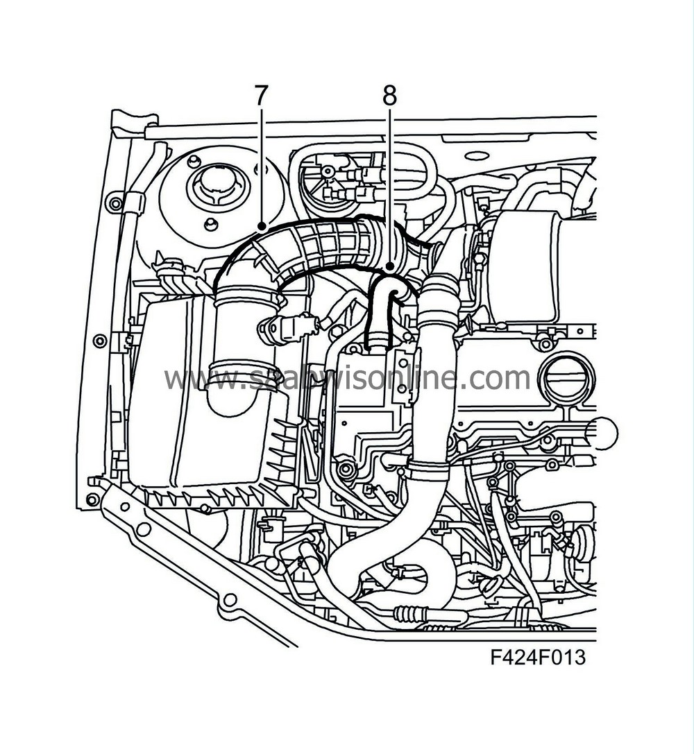
Remove the plug from the intake hose. Connect the hose to the mass air flow sensor.
|
|
8.
|
Remove the plug from the crankcase ventilation hose. Connect the hose to the camshaft cover.
|
|
9.
|
Fit the upper engine cover.

|
|
10.
|
Read the control module software version with Tech 2. If there is a later software version in TIS2000 then this must be programmed into the control module.
|
|
11.
|
If the problems have not been solved, complete the checklist below and get in touch with the importer's technical support. Keep the checklist handy.
|
|
1.
|
Describe the fault symptom .......................................................................................................................................
...................................................................................................................................................
....................................................................................................................................................
|
|
3.
|
Turn off A/C or ACC and let the engine idle. Coolant temperature must be over 80°C.
|
Note
|
|
Diagnostic trouble codes must not be erased.
|
|
|
4.
|
Read and note any diagnostic trouble codes: .......................................................................................................................
|
|
5.
|
Select "Engine" - "Engine management system" - "Read value / Activate" in Tech 2. Read and note the following values:
|
|
|
Unit
|
Ignition On
|
Idling
|
Desired value
|
|
Engine speed
|
rpm
|
-------------
|
|
700-1000
|
|
Fuel mass/Combustion
|
mg/c
|
-------------
|
|
3 - 20
|
|
Air mass/Combustion **
|
mg/c
|
-------------
|
|
200 - 400
|
|
Requested air mass/Combustion **
|
mg/c
|
-------------
|
|
200 - 400
|
|
EGR valve PWM **
|
%
|
-------------
|
|
5 - 95
|
|
EGR valve feedback signal
|
%
|
-------------
|
|
85 - 95
|
|
Mass air flow sensor
|
V
|
|
|
0,85 - 1,15
|
|
Coolant temperature
|
°C
|
|
|
80-100
|
|
Engine oil temperature
|
°C
|
|
|
60 - 120
|
|
Fuel temperature
|
°C
|
|
|
0 - 80
|
|
Intake air temperature
|
°C
|
|
|
20 - 60
|
|
Atmospheric absolute pressure
|
kPa
|
|
|
90-115
|
|
Charge air absolute pressure
|
kPa
|
|
|
90 - 115
|
|
Additive adaptation
|
mg/c
|
|
|
max 0.6
|
** Note! EGR closes after approx. 40-60 seconds after idling speed has been activated. Read the values with EGR active.
Under “system information” there is information on VIN and PSG 16 version number
|
VIN
(obligatory)
|
|
|
Software Module Identifier #1 or Software version
(obligatory)
|
|
|
Programming date
(obligatory)
|
|


