Measurement values, control unit connections PSG 16
|
|
Measurement values, control unit connections PSG 16
|
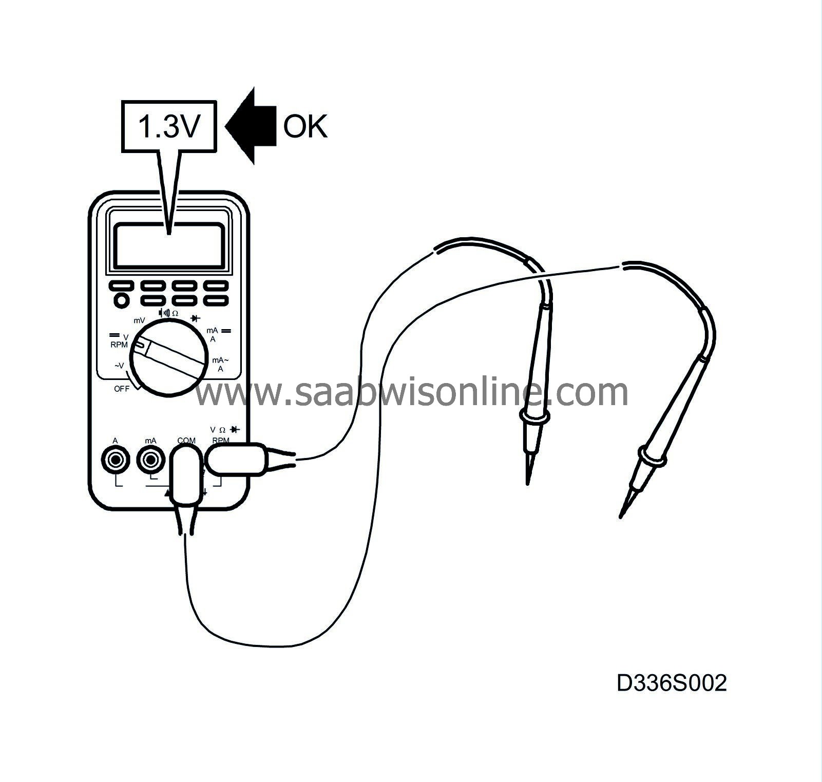
Directions for the measurement of levels and signals at the control module PSG 16 and the measurement values are given on the following pages.
|
•
|
Pay attention to the measurement requirements, use common sense when judging the measurement result.
|
|
•
|
The measurement values which are given are with the ignition ON unless otherwise stated.
|
|
•
|
Check first that there is a voltage supply to the control module and that it is grounded.
|
|
•
|
Then check all sensor inputs and signals from other systems.
|
|
•
|
Lastly check the outputs of the control module. Remember that the output values do not say anything about the functioning of the related actuator.
|
|
•
|
If any measurement value is incorrect, use the wiring diagram to determine which cables, connectors or components should also be checked.
|
|
•
|
The given measurement values are as measured with a calibrated Fluke 88/97.
|
|
•
|
The measurement values %(+) and ms(+) show respectively the pulse ratio and the pulse length. A test instrument with pulse ratio and pulse width measurement must be used. The plus sign (+) denotes a positive trigger pulse, TRIG+.
|
 >= greater than; <= less than
Pins without further comments lack a pin connection. (LP: LOGIC PROBE P= choose pulse; p= visible pulses)
|
Note
|
|
*All units connected to the I and P busses transmit signals.
|
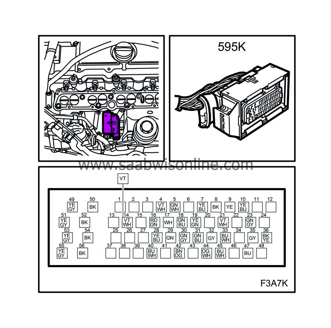
Connector K
|
Pin ( refers to the control module)
|
Colour
|
Component / Function
|
In / Out
|
Measurement requirement.
|
Measurement value
|
Measure between
|
|
4
|
VT/WH
|
Control module, glow plug
|
Out
|
Glow plug not activated
|
10.3 V
|
5-50
|
|
5
|
|
Radiator fan circuit 3
|
Out
|
Radiator fan circuit 3 activated
Radiator fan circuit 3 not activated
|
<0.1 V
B+
|
5-50
5-50
|
|
7
|
YE/BU
|
Power supply measurement Group 3
|
Out
|
|
5 V
|
7-50
|
|
8
|
BK
|
Sensor ground
|
In
|
|
<0.1 V
|
8-50
|
|
9
|
YE
|
Reference ground, pedal position sensor 1
|
In
|
|
<0.1 V
|
9-50
|
|
10
|
YE/BU
|
Relay, +50
|
In
|
Rotation of the starter motor
|
B+
<0.1 V
|
10-28
|
|
14
|
VT/WH
|
Check Engine warning light
|
Out
|
|
B+
|
14-50
|
|
16
|
RD/GN
|
Power supply, +15
|
Out
|
|
<0.1 V
|
16-B+
|
|
17
|
|
P bus- *
|
|
|
2-3V
|
17-50
|
|
19
|
YE/GN
|
Clutch switch, cruise control
|
In
|
Unaffected
Depressed
|
B+
<0.1 V
|
19-50
|
|
21
|
VT/WH
|
Reference ground, pedal position sensor 2
|
In
|
|
<0.1 V
|
21-50
|
|
23
|
GN/GY
|
Relay, +50
|
Out
|
Rotation of the starter motor
|
B+
<0.1 V
|
10-28
|
|
28
|
YE/BU
|
Main relay
|
Out
|
|
<1 V
|
28-50
|
|
29
|
|
P bus+ *
|
|
|
2-3V
|
29-50
|
|
30
|
GN/GY
|
A/C compressor
|
Out
|
Idling, A/C on
|
B+
<0.5 V
|
30-50
|
|
31
|
GN/BU
|
Power supply measurement, Group 2
|
Out
|
|
5 V
|
31-50
|
|
32
|
GY
|
Pressure sensor, A/C
|
In
|
|
1-1.5 V
|
32-50
|
|
33
|
BU/WH
|
Pedal position sensor 1
|
In
|
Unaffected
Depressed
|
<1 V
3.7-3.8 V
|
33-9
|
|
35
|
GY
|
Glow plug control module, signal
|
In
|
|
<0.5 V
|
35-50
|
|
36
|
BK/YE
|
Brake switch, cruise control
|
In
|
Unaffected
Depressed
|
B+
<0.1 V
|
36-50
|
|
40
|
BU/WH
|
Brake lights
|
In
|
Unaffected
Depressed
|
<1.5 V
B+
|
40-50
|
|
44
|
OG/WH
|
Atmospheric pressure sensor
|
In
|
|
4.2 V
|
44-50
|
|
45
|
BU/WH
|
Pedal position sensor 2
|
In
|
Unaffected
Depressed
|
0.5 V
1.8 V
|
45-21
|
|
49
|
YE/GY
|
Main relay
|
In
|
|
B+
|
49-50
|
|
50
|
BK
|
Power ground
|
Out
|
|
B+
|
50-49
|
|
51
|
YE/GY
|
Main relay
|
|
|
B+
|
51-50
|
|
52
|
BK
|
Power ground
|
|
|
B+
|
52-49
|
|
53
|
YE/GY
|
Main relay
|
|
|
B+
|
53-50
|
|
54
|
BK
|
Power ground
|
|
|
B+
|
54-49
|
|
55
|
YE/GY
|
Main relay
|
|
|
B+
|
55-49
|
|
56
|
BK
|
Power ground
|
|
|
B+
|
56-49
|
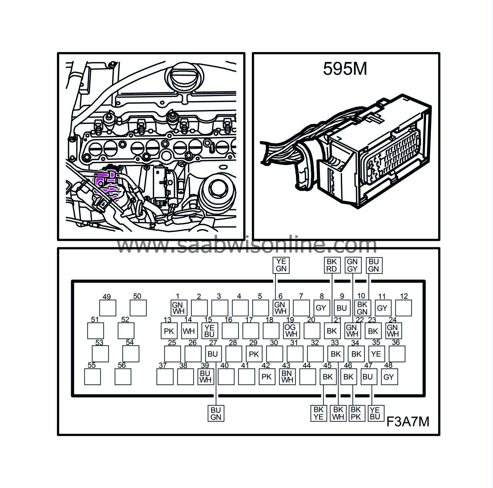
Connector M
|
Pin ( refers to the control module)
|
Colour
|
Component / Function
|
In / Out
|
Measurement requirement.
|
Measurement value
|
Measure between
|
|
1
|
GN/WH
|
Mass air flow sensor
|
Out
|
|
5 V
|
1-47
|
|
6
|
GN/WH
|
Level switch, engine oil
|
Out
|
|
<0.1 V
|
6-B-
|
|
8
|
GY
|
Temperature sensor, coolant
|
Out
|
|
2.9 V
|
8-45
|
|
9
|
BU
|
Absolute pressure sensor
|
In
|
|
1.75 V
|
9-B-
|
|
10
|
BK/GN
|
Mass air flow sensor
|
In
|
|
1.1 V
|
10-B-
|
|
11
|
GY
|
Screen ground
|
In
|
|
<0.1 V
|
11-B-
|
|
13
|
PK
|
Solenoid valve, charge air
|
Out
|
|
5.5 V
|
13-B-
|
|
14
|
WH
|
EGR
|
Out
|
|
10.3 V
|
14-B-
|
|
19
|
OG/WH
|
EGR
|
In
|
|
4.4 V
|
19-B-
|
|
21
|
BK
|
Temperature sensor, engine oil
|
Out
|
|
4.1 V
|
21-33
|
|
22
|
GN/WH
|
Intake air temperature
|
In
|
|
2.2 V
|
22-46
|
|
23
|
BK
|
Crankshaft sensor
|
In
|
Idling
|
1.6 V alternating current
|
23-35
|
|
24
|
GN/WH
|
Pressure switch, engine oil
|
Out
|
Idling
|
<0.1 V B+
|
24-B-
|
|
27
|
|
L-Terminal
|
|
Idling
|
B+ <0.5 V
|
27-B+
|
|
28
|
YE/BU
|
Main relay
|
Out
|
|
B+
|
28-B+
|
|
29
|
PK
|
Solenoid valve, engine shut-off
|
Out
|
|
B+
|
29-B-
|
|
33
|
BK
|
Temperature sensor, engine oil
|
In
|
|
4.1 V
|
33-21
|
|
34
|
BK
|
Level sensor, fuel
|
In
|
|
B+
|
34-B+
|
|
35
|
YE
|
Crankshaft sensor
|
In
|
Idling
|
1.6 V alternating current
|
35-23
|
|
39
|
BU/WH
|
Power supply, Map
|
Out
|
|
5 V
|
39-B-
|
|
42
|
PK
|
Solenoid valve, engine shut-off
|
Out
|
|
B+
|
42-B-
|
|
43
|
BN/WH
|
Solenoid valve, combustion circulation
|
Out
|
|
5.3 V
|
43-B-
|
|
45
|
BK
|
Temperature sensor, coolant
|
In
|
|
2.9 V
|
45-8
|
|
46
|
BK
|
Map, sensor ground
|
In
|
|
5 V
|
46-39
|
|
47
|
BU
|
Mass air flow sensor, reference ground
|
In
|
|
5 V
|
47-1
|
|
48
|
GY
|
Level sensor, fuel
|
Out
|
|
1 V
|
48-34
|