Driver door module (702D)
|
|
Driver door module (702D)
|
The main tasks of the DDM are:
|
•
|
Read the status of the window lift buttons ·
|
|
•
|
Control and supply power for the driver's door window lift (with optional pinch protection function)
|
|
•
|
Send the status for other window lift buttons on the bus.
|
|
•
|
Read the bootlid button status and send the value on the bus.
|
|
•
|
Read the status of the door mirror buttons.
|
|
•
|
Control and supply power for the driver door mirror motors (optional memory function and electrically-operated retraction) and control the corresponding function for the front passenger door via the bus.
|
|
•
|
Supply power to driver's door mirror heating.
|
|
•
|
Read the central lock button status and send the value on the bus.
|
|
•
|
Supply power to central locking system in driver's door with or without TSL, read the central locking system and TSL status and send the value on the bus.
|
|
•
|
The control module also reads the door switch status with an individual lead but does not use the value. The connection is intended for future development.
|
|
•
|
Supply power to door button lighting.
|
|
•
|
Supply power to the courtesy lighting lamp mounted in the lower edge of the door.
|
The DDM has an external button for each window lift. The button has the following positions:
|
•
|
Express up (pinch protection variant only)
|
There is also a button for blocking the rear window lifts. The button is also used to disengage the pinch protection function for the door window lifts and sunroof. In this case, the button must be held down while the window lift in question or the sunroof is being operated. The button has an internal microprocessor with clock, RAM and flash ROM.
An internal bus connects the processor and memory to the I/O unit, which reads values from the A/D converter for analogue inputs, digital inputs, bus and transistor activation in the output stages.
For information on control modules, see
Control modules, general description
.
|
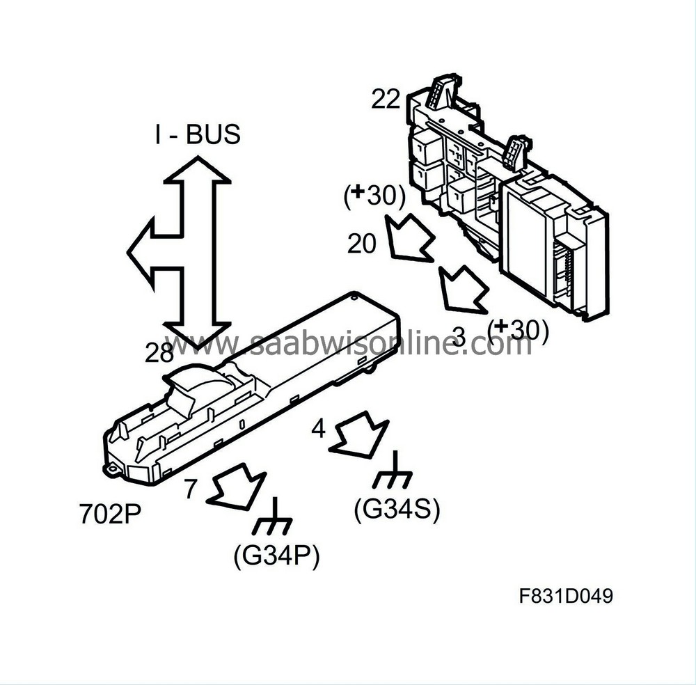
Power supply, ground and bus communication
|
|
Pin
|
Signal type
|
Description
|
|
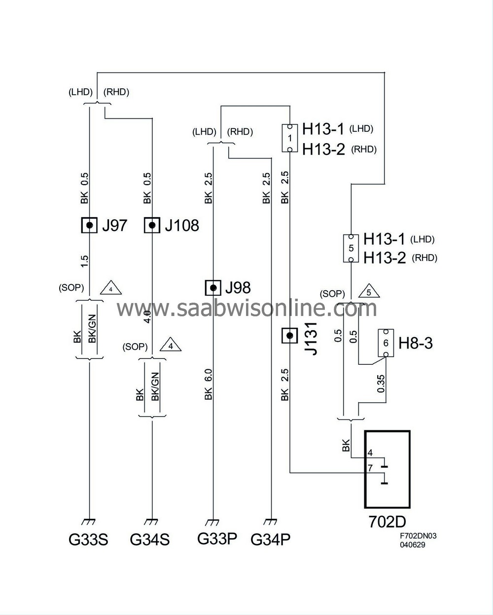
7 (J2)
|
Power ground
|
Power supply
|
|
4 (J1)
|
Signal ground
|
Power supply
|
|
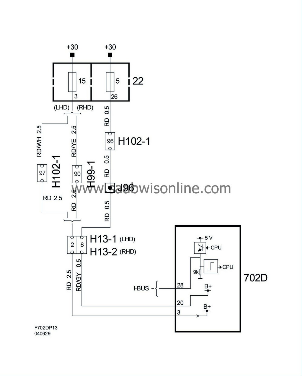
3 (J2)
|
+30 Power
|
Power supply
|
|
20 (J1)
|
+30 Signal
|
Power supply
|
|
28 (J1)
|
Instrument bus
|
Signal on/from other control modules
|