(TA232-0337) Air leak testing, intake system, D223L
|
TECHNICAL ADVICE - Quick information for your help
|
|
Bulletin Nbr:
|
TA232-0337
|
|
Date:
...........
|
July 2003
|
|
Market:
|
All
|
|
|
Air leak testing, intake system, D223L
|
Saab 9-3 and 9-5 (9600) 4-cyl diesel.
The car may have certain fault symptoms without a diagnostic trouble
code being generated. This can be due to an air leak in the intake system.
The following fault diagnosis covers air leak testing of the intake
system . If a diagnostic trouble code arises then relevant fault diagnosis
must first be used . The following method is supplementary if the fault cannot
be located by normal fault diagnosis .
The car may have one or more of the following symptoms:
|
•
|
Engine has uneven/low idling speed
|
|
•
|
Surge or hesitation upon acceleration
|
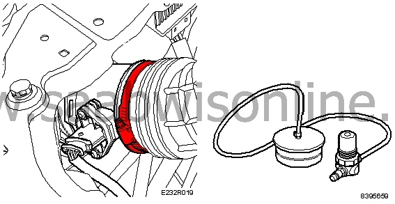
Tools and Materials
83 95 659 Plug set with pressure regulator
30 07 739 Pliers for hose clip
Ø 25 mm plug for the crankcase ventilation hose
Leakage (detection) spray or soap solution
Tech 2
|
1.
|
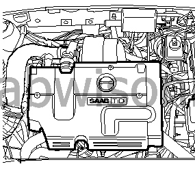
Remove the upper engine cover in order to uncover the intake system.
|
|
2.
|
Undo the crankcase ventilation hose clamp by the camshaft cover
rear section using pliers 30 07 739 and block the hose with a suitable plug
of Ø 25 mm.
Caution
Do
not
plug the hole in the camshaft cover.
It must be possible to evacuate the air that leaks past the pistons down in
the crankcase during test pressurising out through this hole.
|
|
3.
|
Undo the intake hose by the mass air flow sensor. Fit plug 83
95 659 in the hose and then connect the pressure regulator to an external
compressed air outlet.
Caution
Close the pressure regulator before connecting it to the air pressure
outlet.
|
|
4.
|
Connect Tech 2, turn on the ignition and select “Read values
list” for the current engine variant. Scroll forward in the list until
“Charge pressure sensor” in “V” can be seen .
Caution
When the pressure is increased diagnostic trouble code P0106 and P1106
will be generated due to the difference in atmospheric pressure. When a diagnostic
trouble code is generated then “Charge pressure” will indicate
101 kPa, which is the default value when the diagnostic trouble code is set.
For this reason the charge pressure must be read directly on the voltage signal.
|
|
5.
|
Read the voltage from the charge pressure sensor with Tech 2 and
pressurise the intake system by carefully turning the pressure regulator until
a maximum of 2.5 V is reached.
- 6V is corresponds to approx. 100 kPa (atmospheric pressure)
- 5V corresponds to approx. 160 kPa (60 kPa overpressure)
|
|
6.
|
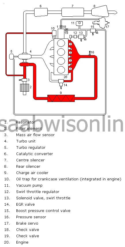
In this way the entire intake system is pressurised and leaks
can be located by using leakage (detection) spray or soap solution which will
bubble and foam around the leak . Inspect all components, hoses and connections
and rectify all audible or visible leaks .
Caution
Only large leaks are of any significance for the functioning of the
engine management system. When leakage (detection) spray or soap solution
is used small leaks will also be discovered. Several small leaks together
can equate to a large leak. Individual very small leaks do not need to be
rectified .
|
|
7.
|
Remove the plug from the intake hose. Connect the hose to the
mass air flow sensor.
|
|
8.
|
Remove the plug from the crankcase ventilation hose. Connect the
hose to the camshaft cover.
|
|
9.
|
Fit the upper engine cover.
|
|
10.
|
Read out the control module software version with Tech 2. If there
is a later software version in TIS2000 then this must be programmed into the
control module.
|
|
11.
|
If the problems have not been solved, complete the Checklist below
and contact the importer's technical support. Have the checklist ready.
|
|
1
|
Describe the fault symptom
......................................................................
......................................................................
......................................................................
|
|
2
|
Connect Tech 2.
|
|
3
|
Switch off the A/C or ACC and let the engine idle. Coolant temperature
must be over 80°C
|
Note
|
|
Diagnostic trouble codes may not be erased.
|
|
|
4
|
Read and note any diagnostic trouble codes:
......................................................................
......................................................................
|
|
5
|
Select "Engine" - "Engine management system" - "Read values" in Tech
2. Read and note the following values:
|
|
|
Unit
|
Ignition On
|
Idle
|
Desired value
|
|
Engine speed
|
rpm
|
............
|
|
700 - 1000
|
|
Fuel mass for combustion
|
mg/c
|
............
|
|
3 - 20
|
|
Air mass/Combustion **
|
mg/c
|
............
|
|
200 - 400
|
|
Requested air mass/combustion **
|
mg/c
|
............
|
|
200 - 400
|
|
EGR valve PWM **
|
%
|
............
|
|
5 - 95
|
|
EGR valve feedback signal
|
%
|
............
|
|
85 - 95
|
|
Mass air flow sensor
|
V
|
|
............
|
0,85 - 1,15
|
|
Coolant temperature
|
°C
|
|
|
80 - 100
|
|
Oil temperature, engine
|
°C
|
|
|
60 - 120
|
|
Fuel temperature
|
°C
|
|
|
0 - 80
|
|
Intake air temperature
|
°C
|
|
|
20 - 60
|
|
Atmospheric absolute pressure
|
kPa
|
|
|
90 - 115
|
|
Charge air absolute pressure
|
kPa
|
|
|
90 - 115
|
** Note: EGR is closed after approx. 40-60 seconds after idling speed
has been activated.
Read the values with EGR active.
Under "All" - "ECU Information / System information" - "ECM" there is
information on Vehicle Identification Number and software version for Trionic
8.
|
Chassis number
(compulsory)
|
|
|
Software Module Identifier #1 or Software Version
(compulsory)
|
|
|
Programming date
(compulsory)
|
|
