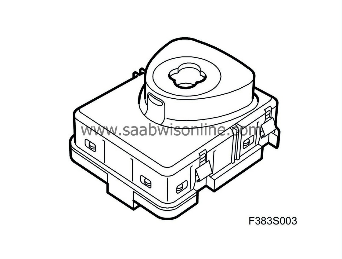
Ignition switch unit (20)
|
|
Ignition switch unit (20)
|
Ignition switch unit (20)
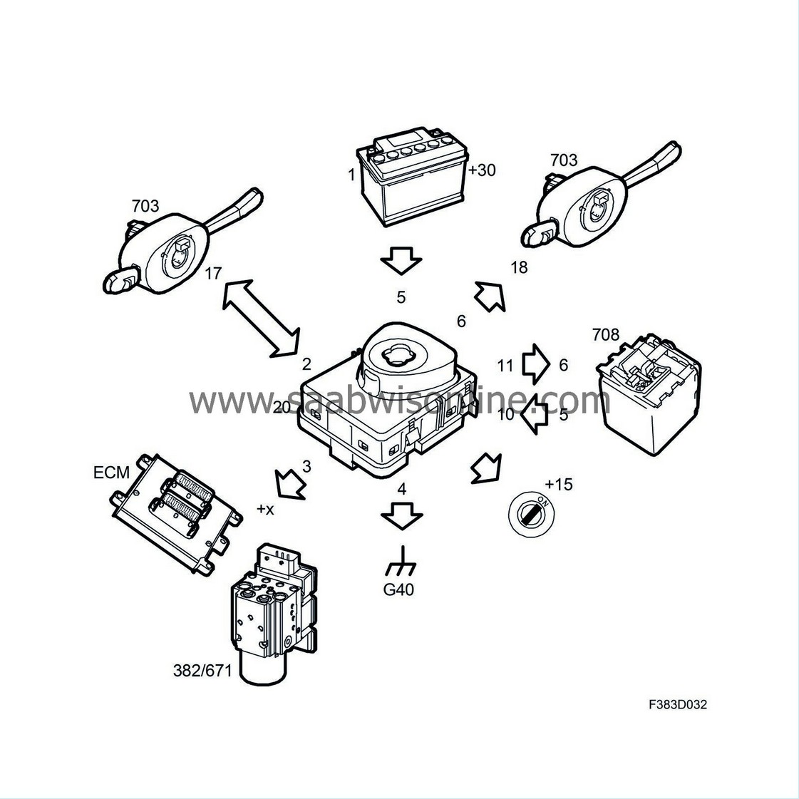
The ignition switch (ISM) is linked with the column integration module (CIM) and the steering column lock (SCL) and has the following uses:
|
•
|
Send the transponder code to CIM via the communication cable for identification.
|
|
•
|
Send the key position to CIM via the communication cable for forwarding to the buses.
|
|
•
|
Send the remote control battery status to CIM via the communication cable in order to display a battery warning on SID.
|
|
•
|
Prevent the key being turned from LOCK to OFF before the transponder code has be approved and SCL unlocked.
|
|
•
|
Prevent the key being turned from OFF to LOCK before the car has stopped and the selector lever has been moved to P (aut).
|
|
•
|
Release the SCL locking pin via a direct lead prior to locking the steering column after a command on the communication cable from CIM.
|
|
•
|
Find out via a direct lead from SCL that the locking pin is in unlocked and released position and send it to CIM on the communication cable.
|
|
•
|
Illuminate the key positions.
|
|
•
|
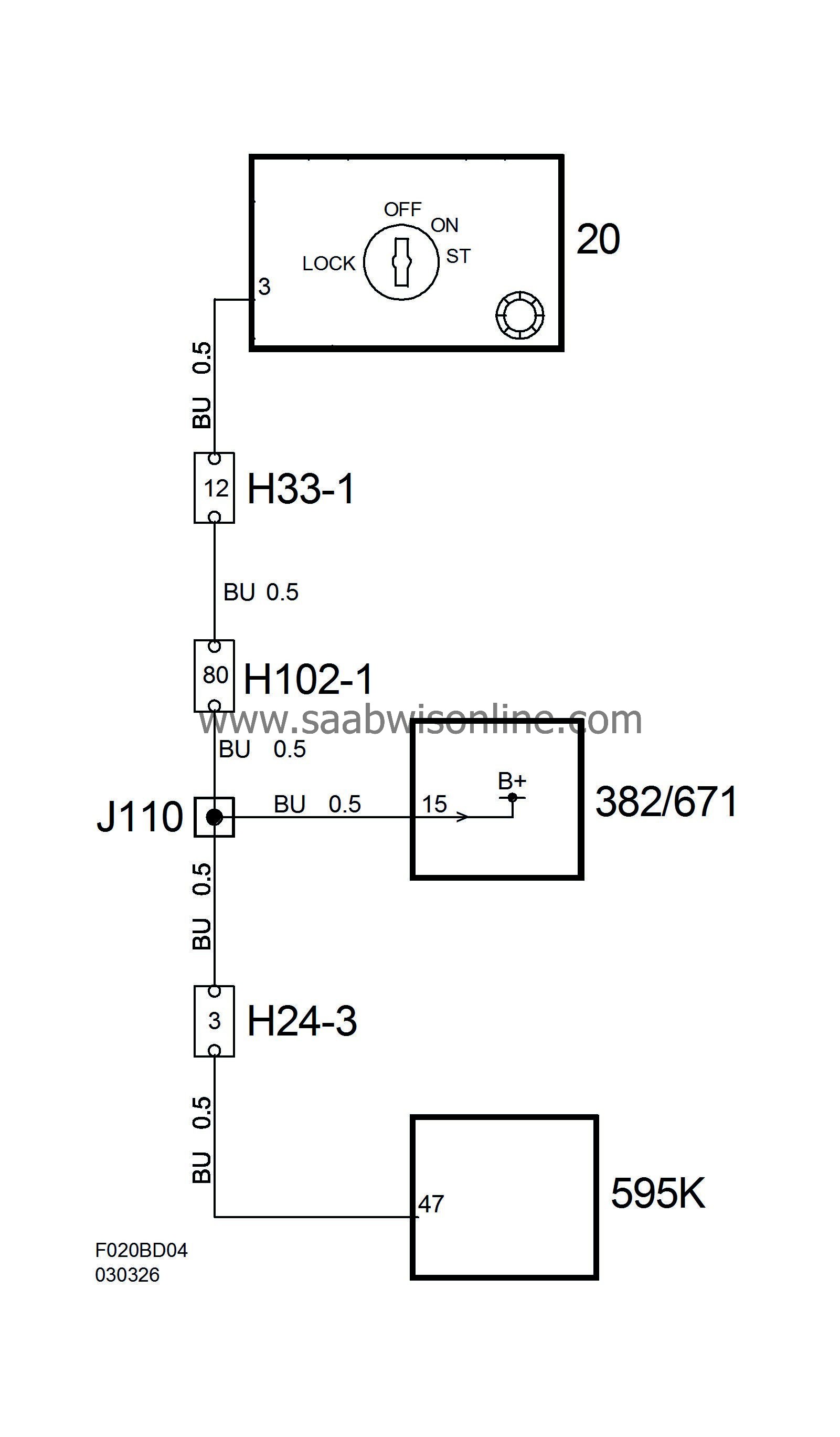
Provide a number of units with battery voltage via a direct lead in certain key positions.
|
ISM is a unit that contains the following components:
|
•
|
Ignition switch with four positions, LOCK, OFF, ON and ST, and a switch to indicate that the key is inserted.
|
|
•
|
Solenoid to prevent the key from being turned from LOCK to OFF and from OFF to LOCK.
|
|
•
|
Transponder antenna for identifying the key transponder.
|
|
•
|
Illumination for key positions.
|
|
Pin no.
|
Signal type
|
Description
|
|
2
|
Communication cable
|
Communication with CIM.
|
•
|
Key transponder code to CIM.
|
|
•
|
SCL locking pin in unlocked and secured position to CIM.
|
|
•
|
Release SCL locking pin, command from CIM.
|
|
•
|
Brightness value for key positions from CIM.
|
|
|
3
|
+X
|
Signal and supply to
|
•
|
TCS control module/EPS control module
|
|
|
4
|
Ground
|
Power supply
|
|
5
|
+30
|
Power supply
|
|
6
|
+B
|
Wake-up signal to CIM.
|
|
10
|
Locking pin is in unlocked and secured position.
|
Hall sensor value. Signal from SCL.
|
|
11
|
Release locking pin.
|
Signal to SCL.
|
|
12
|
+15
|
Signal and supply to
|
•
|
All P-bus control modules.
|
|
•
|
Underhood electrical centre (UEC).
|
|
•
|
Rear electrical centre (REC).
|
|
•
|
Fuse box in instrument panel.
|
|
Power supply
Output +15
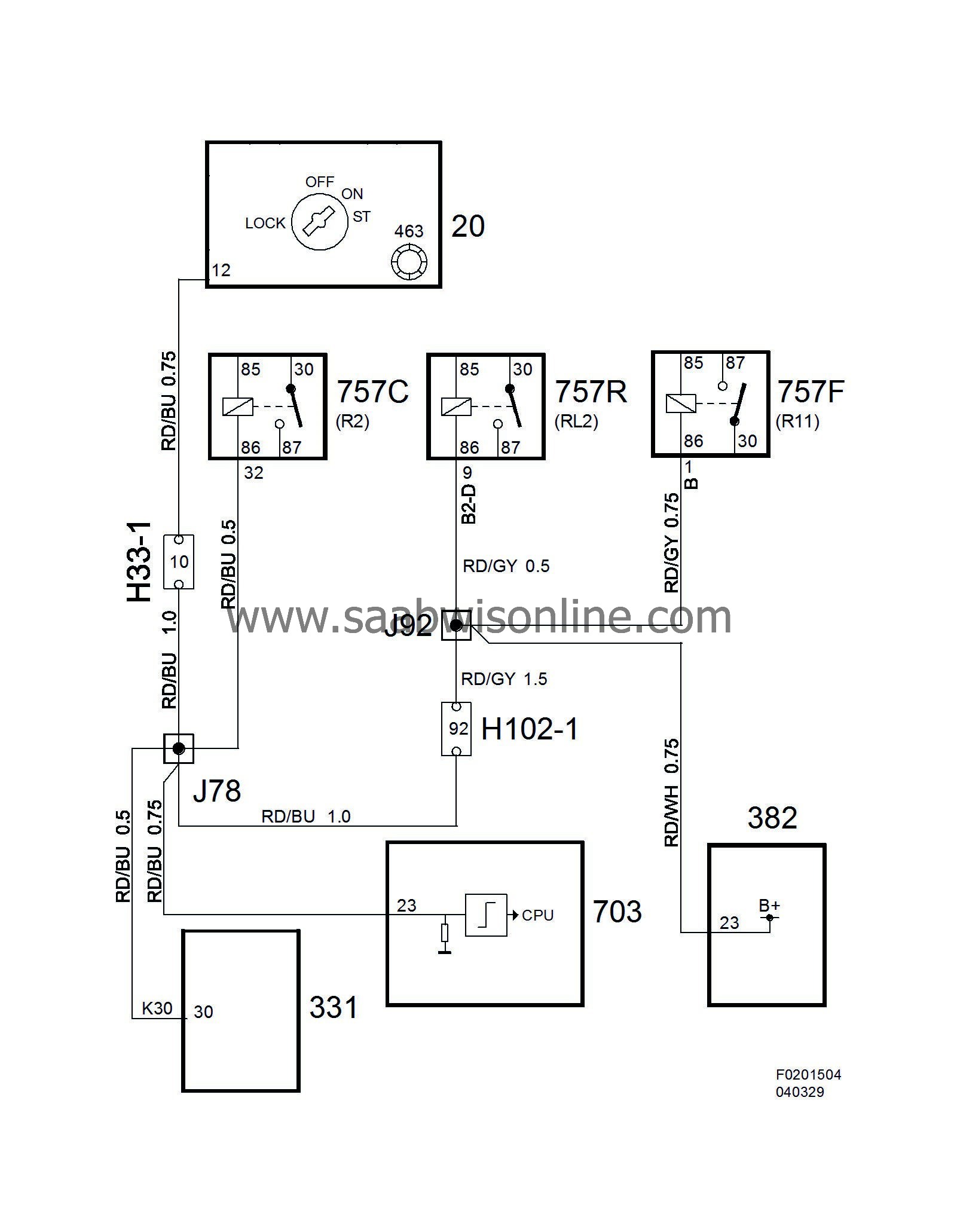
Output +X, T8
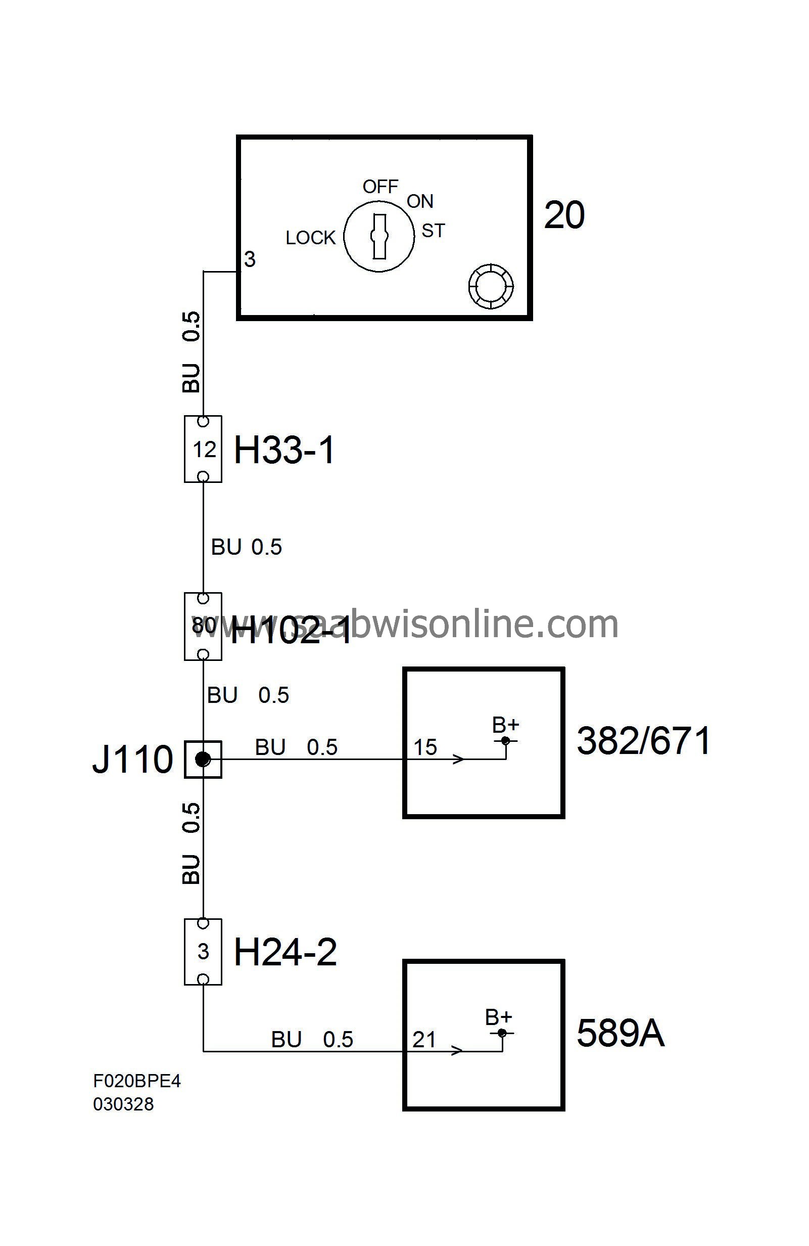
Output +X, Simtec
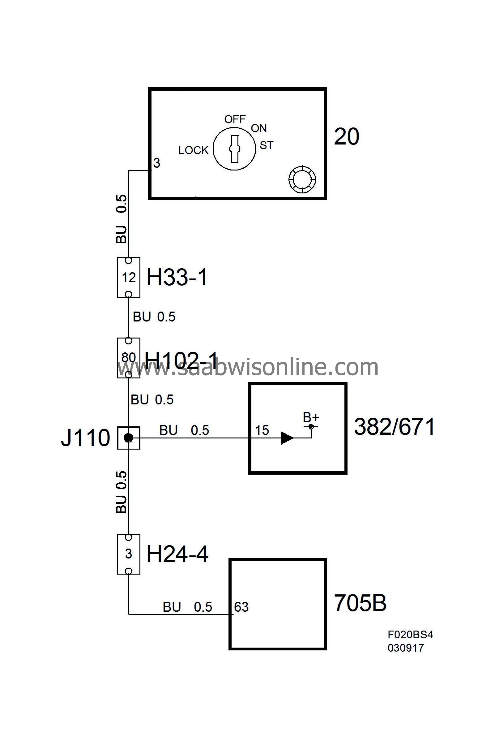
Output +X, PSG16