Diesel pump with control module (595)
|
|
Diesel pump with control module (595)
|
 Warning
|
|
The work involved in removing the fuel pump requires working with the vehicle's fuel system. The following points should therefore be heeded in conjunction with these measures:
|
|
|
|
|
|
|
•
|
Ensure good ventilation! If there is approved ventilation for evacuating fuel fumes then this must be used.
|
|
•
|
Wear protective gloves! Prolonged exposure of the hands to fuel can cause irritation to the skin.
|
|
•
|
Have a class BE fire extinguisher on hand! Be aware of the risk of sparks, i.e. in connection with electric circuits, short-circuiting, etc.
|
|
Important
|
|
ESD-SENSITIVE COMPONENT
|
|
Earth yourself by touching the car body before plugging in / unplugging components.
Do not touch the component pins
. Read
Before removing a control module
before changing a control module.
|
|
|
|
1.
|
Loosen the expansion tank cap and release any excess pressure.
|
|
3.
|
Remove the front right wheel.
|
|
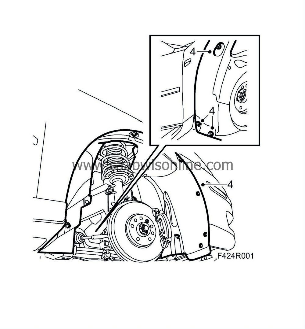
4.
|
Remove the right-hand wheel arch liner.
|
|
6.
|
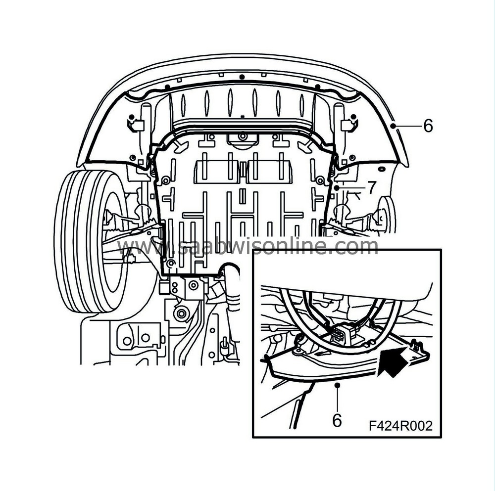
Remove the front spoiler shield. Detach the headlamp washer hose and unplug and remove the connector.
|
|
7.
|
Remove the lower engine cover.
|
|
8.
|
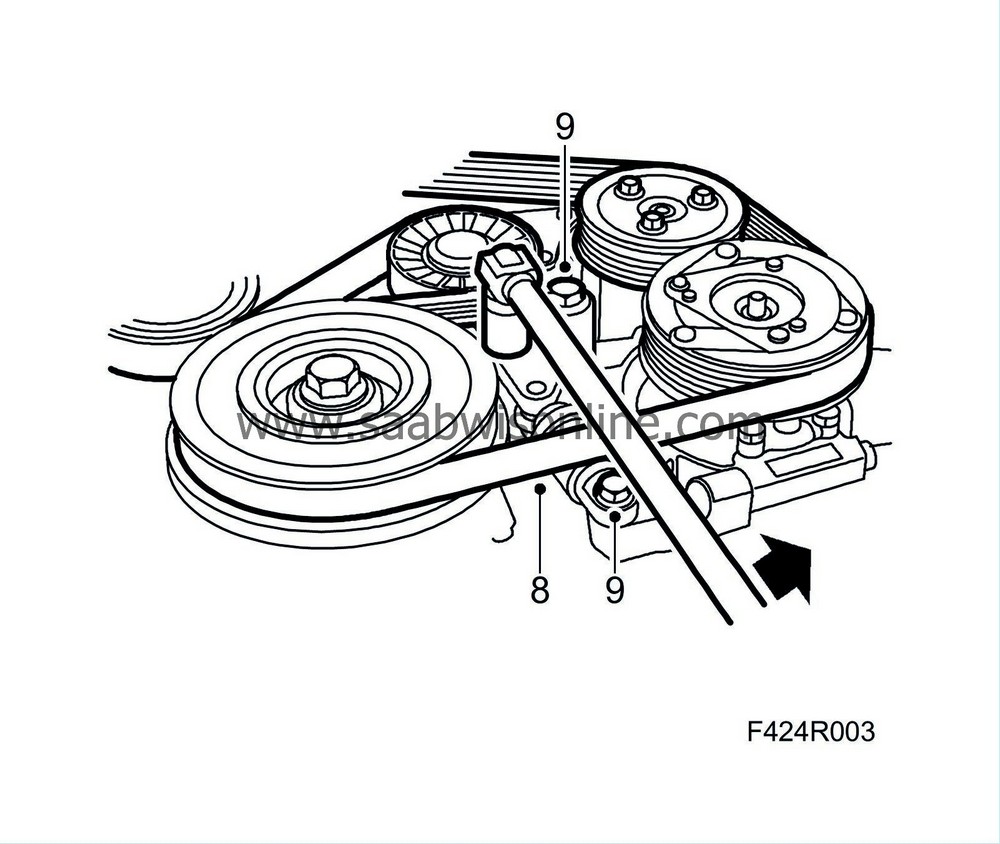
Mark the direction of rotation. Then unload and remove the Poly-V belt.
|
|
9.
|
Remove the belt tensioner. Store the belt tensioner upright. See marking.
|
|
10.
|
Place a receptacle under the car, connect a hose and drain the cooling system.
|
|
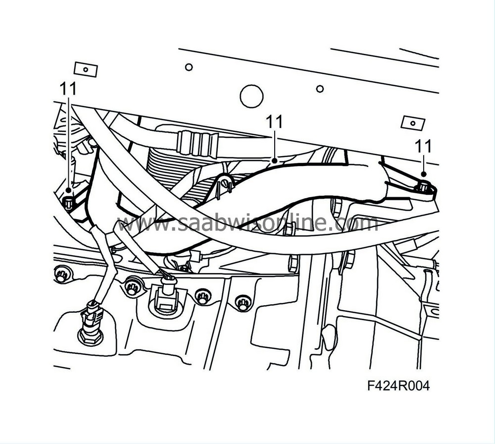
11.
|
Loosen the coolant pipe screws.
|
|
13.
|
Remove the upper engine cover.
|
|
14.
|
Unplug the connector from the mass air flow sensor.
|
|
15.
|
Detach the hose from the crankcase ventilation.
|
|
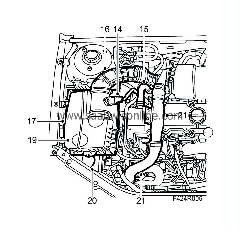
16.
|
Detach the inlet hose from the turbocharger. Cover the turbocharger inlet.
|
|
17.
|
Remove the cover of the air filter housing.
|
|
18.
|
Remove the air filter.
|
|
19.
|
Detach the intake air hose from the air filter housing.
|
|
20.
|
Remove the air filter housing. Be careful so as not to damage the A/C pressure sensor.
|
|
21.
|
Remove the charge air hose with charge air pipe from the turbocharger and the charge air pipe on the fan cowling. Plug the connections.
|
|
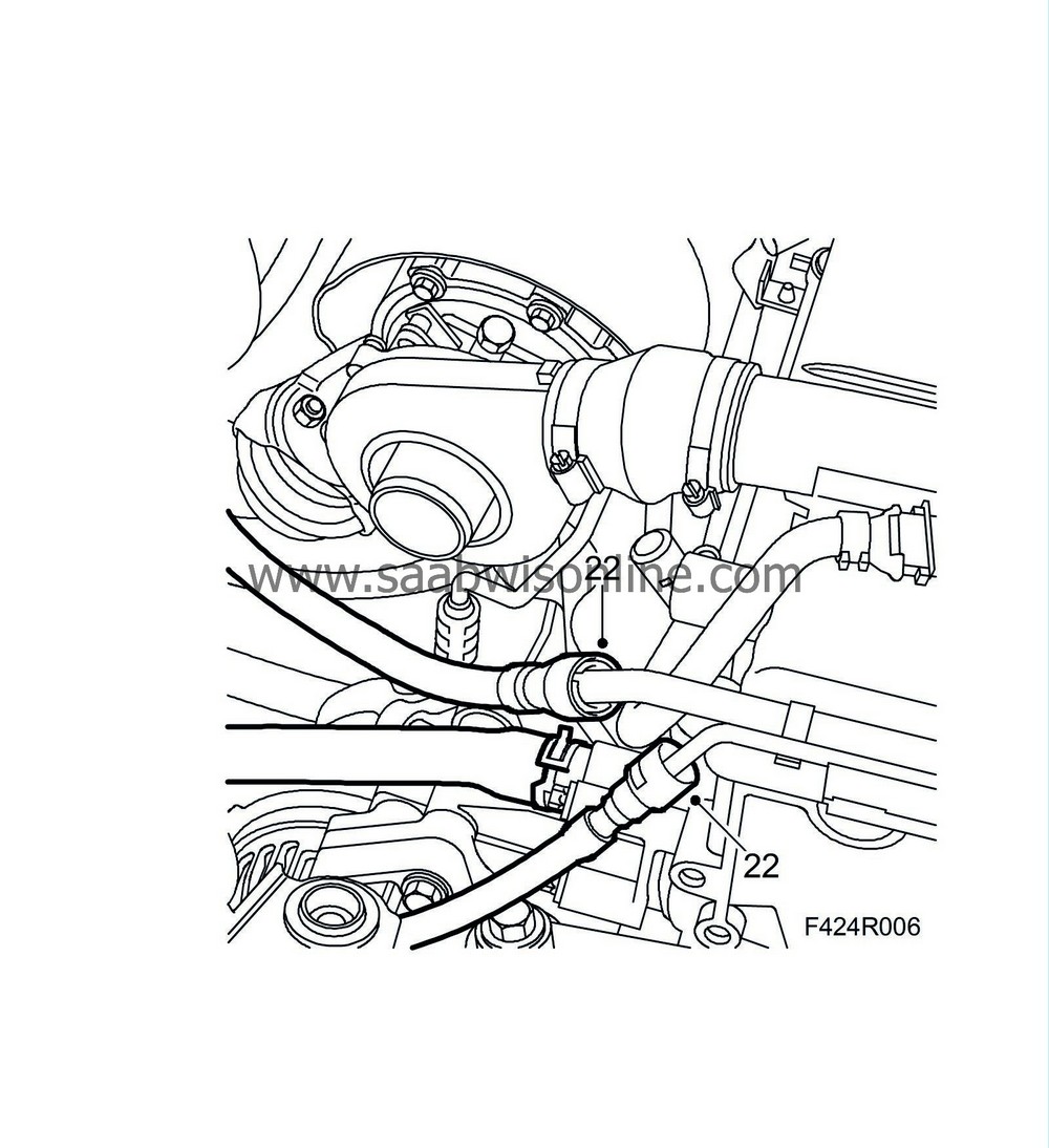
22.
|
Detach the fuel lines using
83 95 261 Fuel line tool
and seal them. Have a cloth or the like on hand to catch any fuel spill.
|
|
23.
|
Detach the boost pressure hose from the throttle body and put it to the side.
|
|
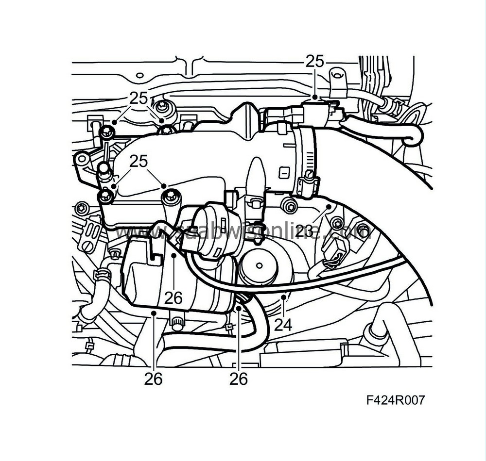
24.
|
Detach the vacuum hose from the throttle body.
|
|
25.
|
Remove the throttle body.
|
|
26.
|
Detach the EGR valve connector and coolant hoses. Remove the EGR valve from the intake manifold.
|
|
27.
|
Place a receptacle under the car to catch fuel spill. Detach the fuel return hoses from the fuel bridges.

|
|
28.
|
Mark the position of the fuel rails with clamps and remove them.
|
|
29.
|
Remove the upper section of the intake manifold.
|
|
30.
|
Detach the hoses from the thermostat housing.

|
Important
|
|
Take care when releasing the locking mechanism on the connector so as not to damage the connector. Pull the halves straight apart to avoid bending the pins. For further information regarding connectors, refer to
Connectors, handling and inspection
.
|
|
|
|
|
31.
|
Unplug the connectors of the A/C pressure sensor, coolant temperature sensor and the engine control module.
|
|
32.
|
Cut off the cable tie securing the coolant pipe. Move aside the wiring from the engine control module.
|
|
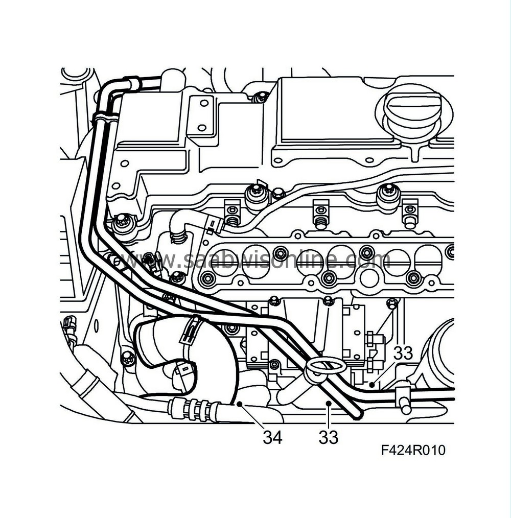
33.
|
Detach the supply and return fuel leads from the fuel distribution pump.
|
|
34.
|
Detach the coolant pipe with hose and move it aside.
|
|
35.
|
Detach and move aside the cable guides.
|
|
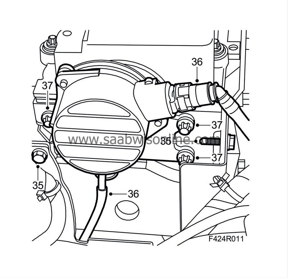
36.
|
Detach the vacuum hose of the brake servo and the vacuum hose connected to the bottom of the vacuum pump.
|
|
37.
|
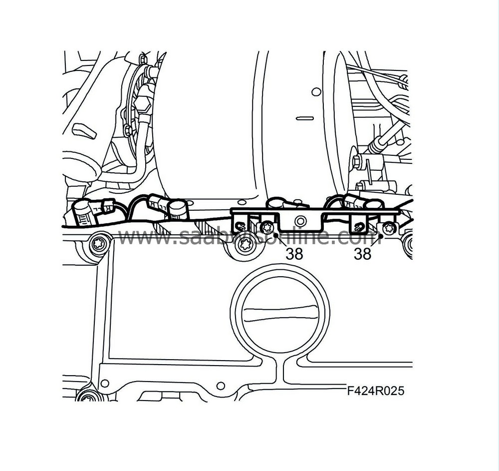
Remove the four retaining bolts of the vacuum pump and carefully lift out the pump and its adapter. Have a cloth or the like on hand to catch any oil spill.
|
|
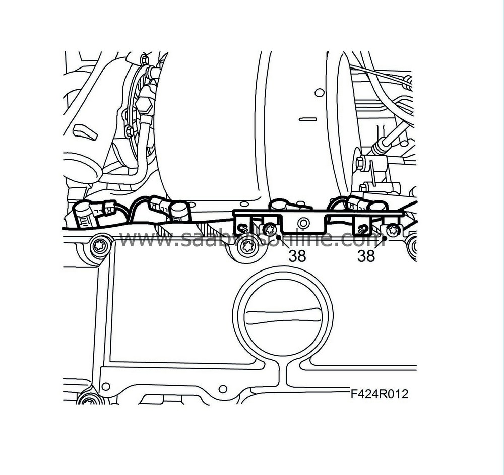
38.
|
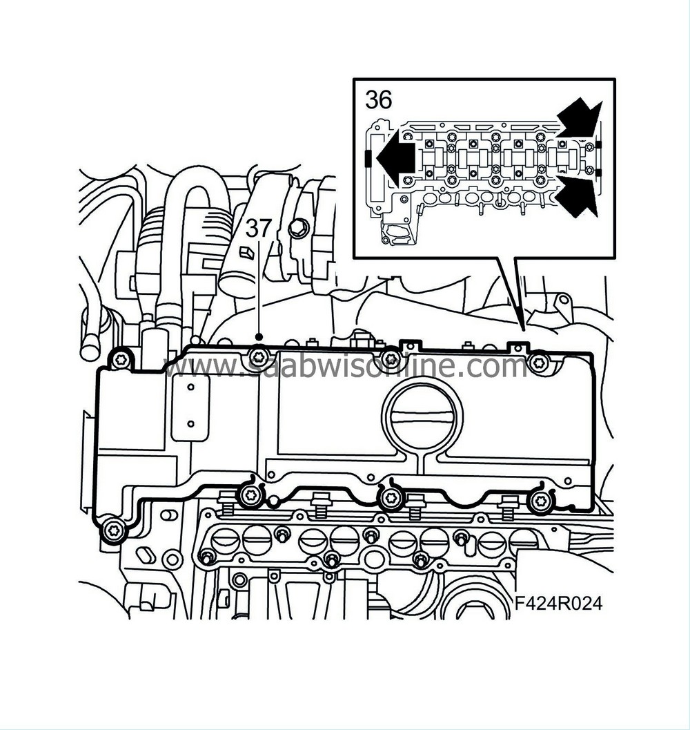
Loosen the rear mounting of the wiring harness from the camshaft cover.
|
|
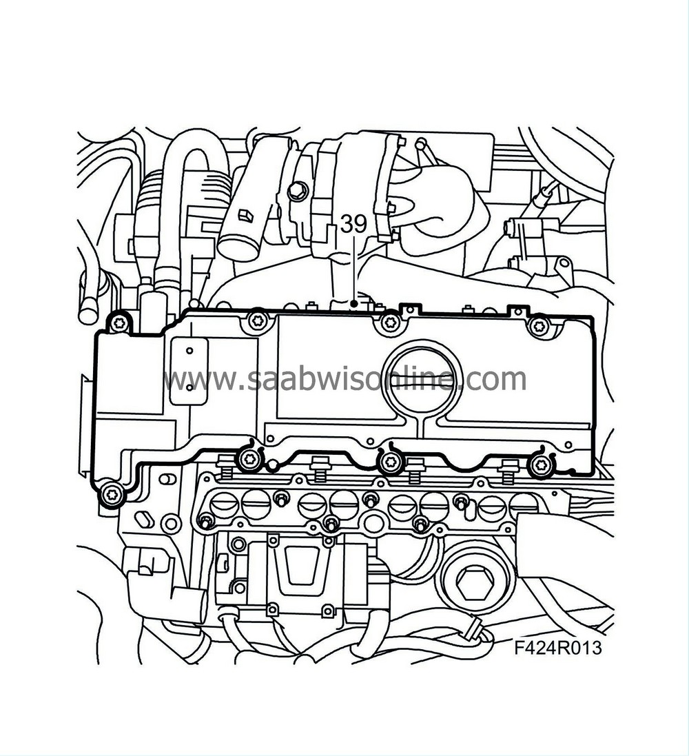
39.
|
Remove the camshaft cover.
|
|
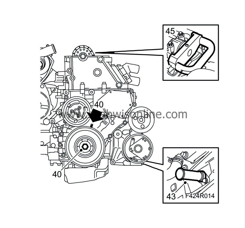
40.
|
Rotate the crankshaft to just before the TDC marking in cylinder 1. Check that both cam lobes for cylinder 1 point upwards on an angle.
|
|
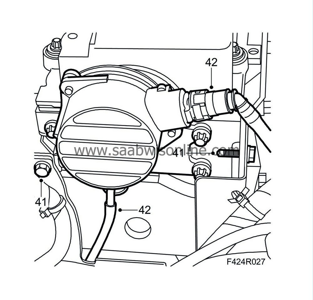
42.
|
Remove the crankshaft position sensor.
|
|
43.
|
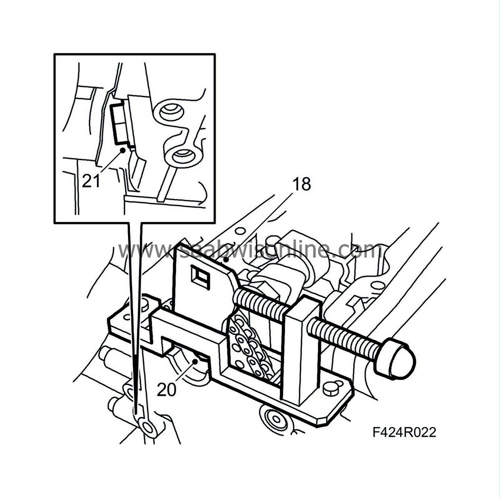
Insert
83 95 352 Adjustment tool, crankshaft
in the hole for the crankshaft position sensor. Press the tool in while rotating the crankshaft to its zero mark. The tool will then go into a socket in the crankshaft and lock it.
|
|
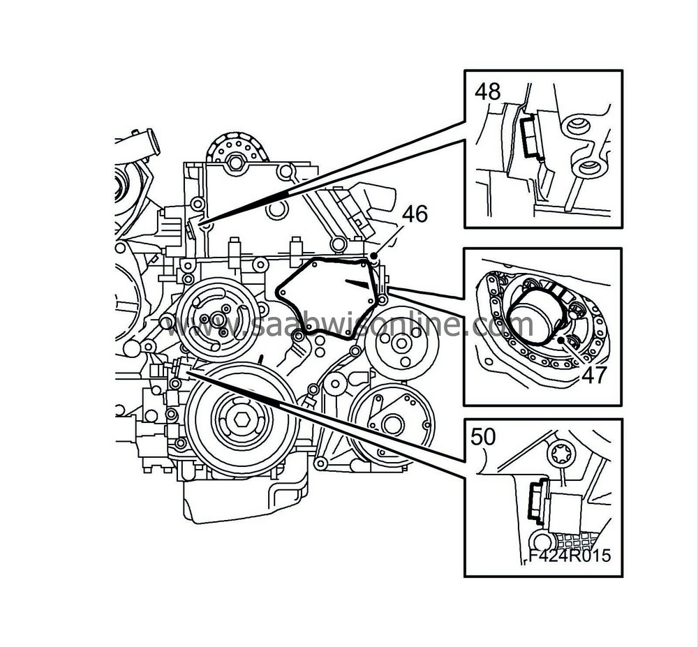
46.
|
Remove the screws of the timing cover lid, carefully insert a putty knife behind the lid and carefully prising it loose.
|
Important
|
|
Take care, otherwise the cover can be distorted and cause leaks.
|
|
|
|
|
48.
|
Remove the upper timing chain tensioner.
|
|
50.
|
Remove the lower timing chain tensioner.
|
|
53.
|
Secure the upper timing chain to the camshaft gear with a cable tie.
|
|
54.
|
Remove the camshaft gear using an open wrench as counterstay in the hexagonal socket on the camshaft.
|
|
55.
|
Loosen the screws of the fuel distribution pump sprocket and remove the sprocket.
|
Important
|
|
The centre nut must
absolutely not
be undone.
|
|
|
|
|
56.
|
Pull the chain up and remove it.
|
|
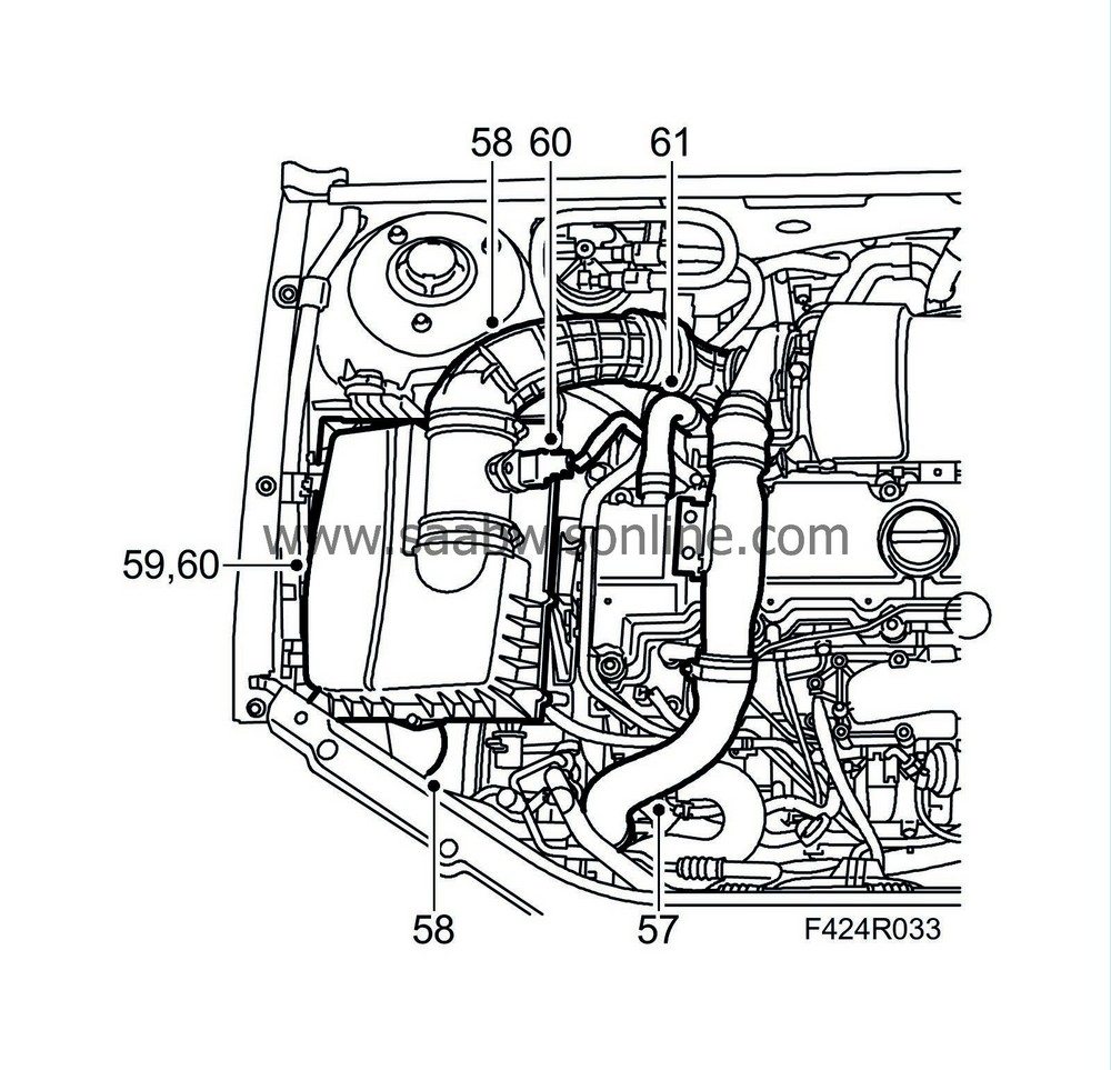
58.
|
Place a receptacle under the car. Loosen the drain nipple, 8 mm socket. Connect a hose to the engine block drain nipple. Drain the coolant.
|
|
59.
|
Remove the drain nipple.
|
|
60.
|
Remove the bracket screw from the cylinder block and remove the fuel pump.
|
Important
|
|
ESD-SENSITIVE COMPONENT
|
|
Earth yourself by touching the car body before plugging in / unplugging components.
Do not touch the component pins
. Read
Before removing a control module
before changing a control module.
|
|
|
|
|
1.
|
Clean the sealing surfaces.
|
|
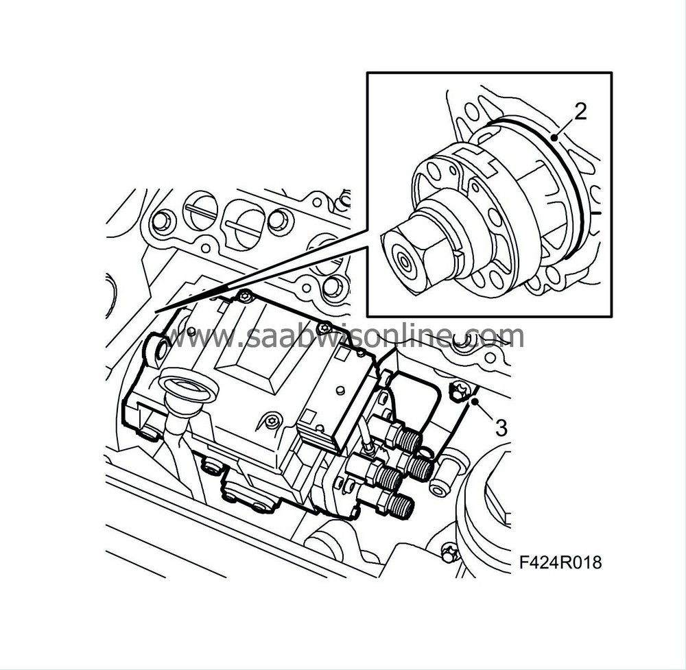
2.
|
Lubricate a new O-ring with acid-free vaseline and fit it to the fuel distribution pump. Fit the pump to the cylinder block. If replacing the pump, transfer the bracket to the new pump.
Tightening torque 20 Nm (15 lbf ft)
|
|
3.
|
Insert the screw for the bracket in the cylinder block without tightening it.
|
|
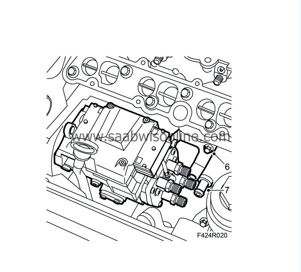
6.
|
Tighten the screw securing the bracket to the cylinder block.
Tightening torque 20 Nm (15 lbf ft)
|
|
7.
|
Fit the engine block drain plug using a new O-ring.
|
|
8.
|
Remove the inspection gauge from the fuel distribution pump.
|
|
9.
|
Lower the upper timing chain, fit the fuel distribution pump sprocket using a screw, fit the chain and tighten the sprocket screws by hand.
|
Important
|
|
The arrow on the sprocket must be aligned with the recess on the flange and the hole in the pump.
|
|
|
|
|
11.
|
Fit the camshaft gear to the camshaft.
|
|
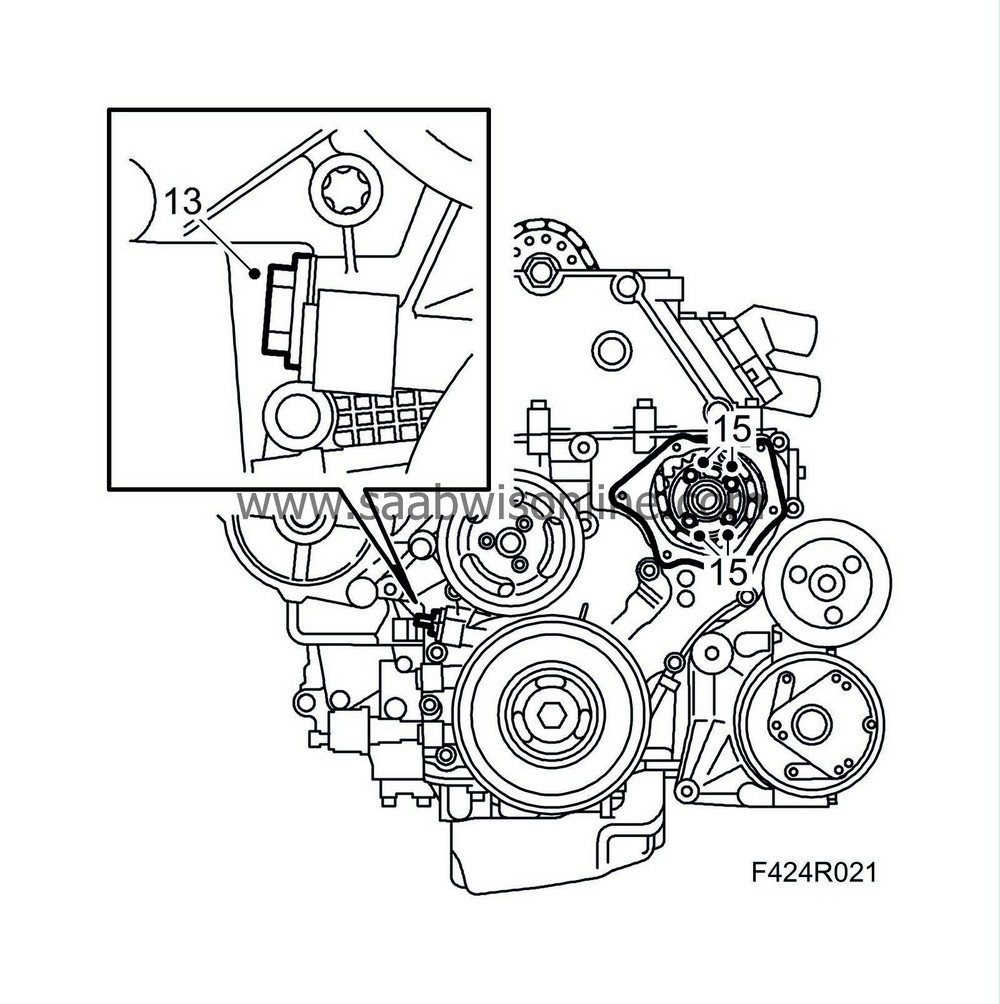
13.
|
Fit the chain tensioner for the lower timing chain using a new gasket.
Tightening torque 60 Nm (44 lbf ft)
|
|
15.
|
Remove the inspection gauge from the fuel distribution pump and tighten the sprocket screws.
Tightening torque 20 Nm (15 lbf ft)
|
|
16.
|
Refit the inspection gauge in the fuel distribution pump socket.
|
|
17.
|
Check that the camshaft gear runs freely on the camshaft and fit a new screw. Tighten by hand.
|
|
19.
|
Secure the position of the adapter on the camshaft gear by gently turning anticlockwise using a lock handle. Tighten the adjuster screw on the tool.
|
Important
|
|
Adjustment tool, fuel pump 83 95 337 must be easy to remove and fit at all times. If not, slacken the adjusting screw on the tool slightly
|
|
|
|
|
20.
|
Tighten the camshaft gear screw. Use an open wrench as counterstay in the hexagonal socket on the camshaft.
Tightening torque 90 Nm (67 lbf ft) + 60°
|
|
21.
|
Fit the chain tensioner for the upper timing chain using a new gasket.
Tightening torque 60 Nm (44 lbf ft)
|
|
23.
|
Rotate the crankshaft two revolutions to just before the TDC marking in cylinder 1. Check that both cam lobes for cylinder 1 point upwards on an angle.
|
|
25.
|
Insert
83 95 352 Adjustment tool, crankshaft
in the hole for the crankshaft position sensor. Press the tool in while rotating the crankshaft to its zero mark. The tool will then go into a socket in the crankshaft and lock it.
|
|
27.
|
Check that the markings on the crankshaft pulley and timing cover line up. The arrow on the single timing chain gear at the fuel distribution pump should line up with the socket in the pump.
|
|
31.
|
Fit the crankshaft position sensor using a new O-ring.
|
|
32.
|
Cover the timing cover opening with a lint-free cloth and clean any gasket residue from the sealing surface. Clean the sealing surface on the lid as well.
|
|
33.
|
Apply a 2 mm thick string of
83 95 691 Flange sealant
to the lid, remove the cloth from the timing cover and fit the lid.
Tightening torque 6 Nm (5 lbf ft)
|
|
34.
|
Clean any gasket residue from the cylinder head sealing surfaces.
|
|
35.
|
Fit a new gasket on the camshaft cover. The screws have sleeves on which the gasket rests.
|
|
37.
|
Position the camshaft cover on the cylinder head and tighten the screws.
Tightening torque 8 Nm (6 lbf ft)
|
|
38.
|
Fit the rear mounting of the wiring harness to the camshaft cover.
|
|
39.
|
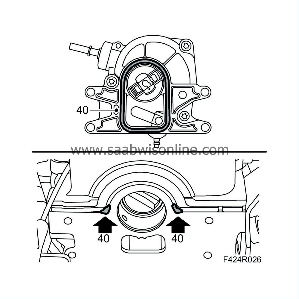
Clean the sealing surfaces of the vacuum pump and the cylinder head.
|
|
40.
|
Fit a new gasket to the vacuum pump, apply
83 95 691 Flange sealant
as illustrated and fit the pump together with the adapter.
Tightening torque 8 Nm (6 lbf ft)
|
|
41.
|
Fit the cable guides.
|
|
42.
|
Connect the vacuum hoses to the vacuum pump.
|
|
43.
|
Connect the coolant pipe with hose.

|
|
44.
|
Fit a new fuel return hose to the supply lead. Fit the supply and return fuel leads to the fuel pump using new sealing washers. Do not completely tighten the connections.
Connect the fuel leads to the leads from the tank, adjust the leads to the socket in the camshaft cover and completely tighten the connections to the fuel pump.
Hold the fuel leads so that they do not rotate when tightened.
Tightening torque 25 Nm (19 lbf ft)
|
Important
|
|
Take care when plugging in the connector so as not to damage or press out the pins/sleeves in the connector. For further information regarding connectors, refer to
Connectors, handling and inspection
.
|
|
|
|
|
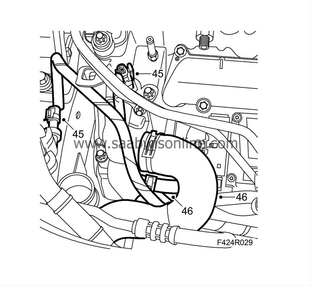
45.
|
Plug in the connectors to the fuel pump control module, coolant temperature sensor and AC pressure sensor.
|
Important
|
|
ESD-SENSITIVE COMPONENT
|
|
Earth yourself by touching the car body before plugging in / unplugging components.
Do not touch the component pins
. Read
Before removing a control module
before changing a control module.
|
|
|
|
|
46.
|
Fit the coolant hoses to the thermostat housing.
|
|
47.
|
Secure the wiring to the coolant pipe with a cable tie.
|
|
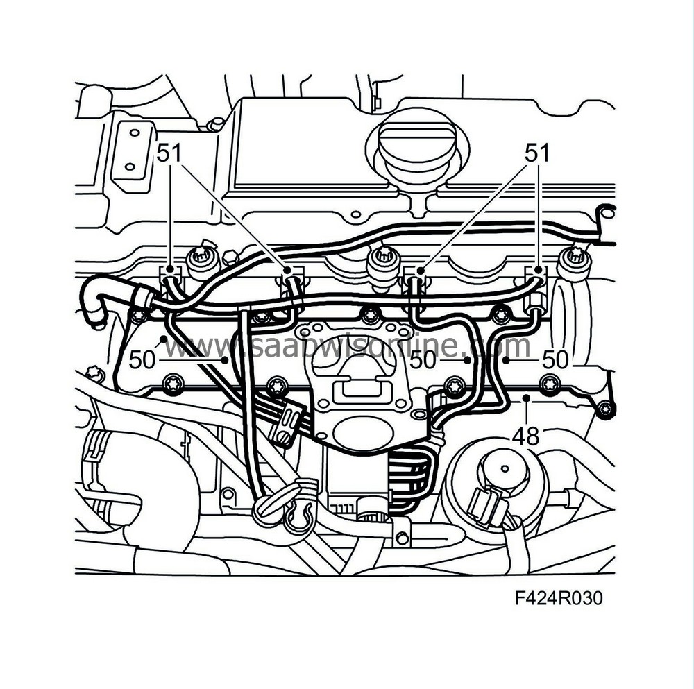
48.
|
Clean the sealing surfaces of the upper section of the intake manifold. Fit the upper section using a new gasket.
Tightening torque 10 Nm (7 lbf ft)
|
|
49.
|
Check the connecting cones of the fuel rails. If they are damaged, the rail must be replaced.
|
|
50.
|
Fit the fuel rails.
Tightening torque 25 Nm (19 lbf ft)
|
|
51.
|
Fit new fuel return hoses to the fuel bridges and connect the fuel return hose fitted earlier.
|
|
52.
|
Fit the EGR valve using a new O-ring.
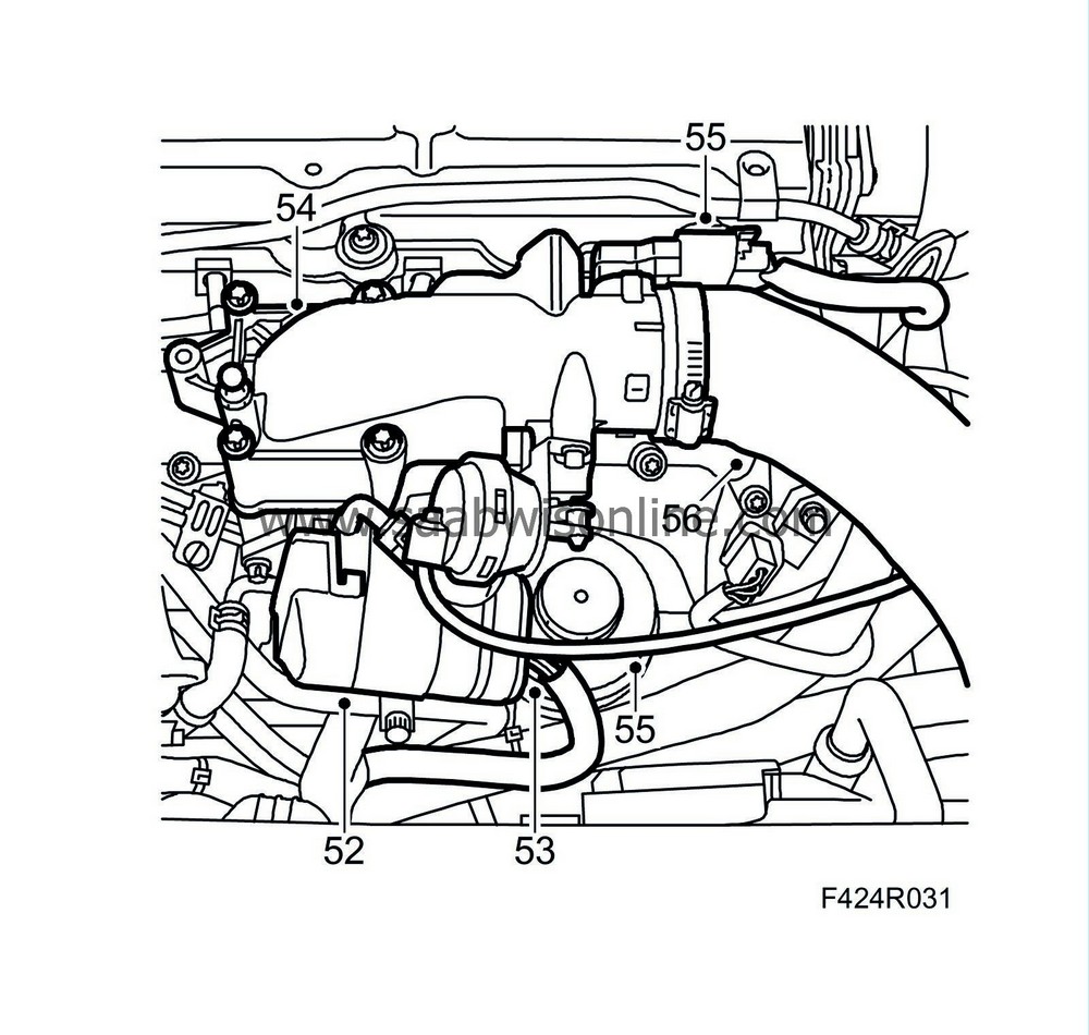
Tightening torque 10 Nm (7 lbf ft)
|
|
53.
|
Plug in the EGR valve connector and attach its coolant hoses.
|
|
54.
|
Fit the throttle body using a new gasket.
Tightening torque 10 Nm (7 lbf ft)
|
|
55.
|
Fit the connector and vacuum hose to the throttle body.
|
|
56.
|
Fit the turbo pressure hose to the throttle body.
|
|
57.
|
Remove the plugs, fit the charge air hose with charge air pipe to the turbocharger and the charge air pipe to the fan cowling.
|
|
58.
|
Fit the inlet hose for the air filter housing. Fit the air filter housing.
|
|
60.
|
Fit the cover of the air filter housing.
|
|
61.
|
Fit the inlet hose from the mass air flow sensor to the turbocharger and the hose for crankcase ventilation.
|
|
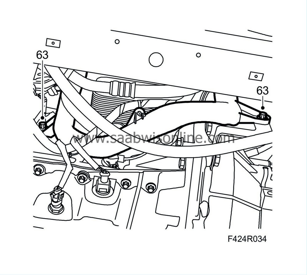
63.
|
Fit the coolant pipe screws.
|
|
64.
|
Check that the coolant drain cock is closed.
|
|
65.
|
Fit the belt tensioner, tightening the upper screw first.
Tightening torque 42 Nm (31 lbf ft)
|
|
66.
|
Tighten the lower screw.
Tightening torque 23 Nm (17 lbf ft)
|
|
67.
|
Check that the pulleys are clean and dry.
|
|
68.
|
Fit the Poly-V belt matching the mark made previously and check that it sits correctly over the pulleys.
|
|
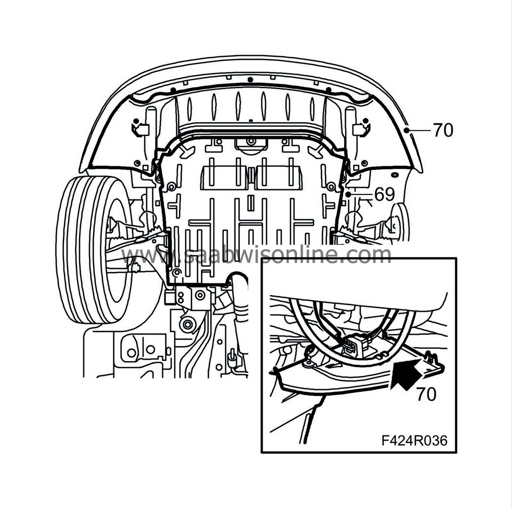
69.
|
Fit the lower engine cover.
|
|
70.
|
Fit the front spoiler shield. Fit and plug in the connector. Connect the headlamp washer hose.
|
|
71.
|
Fit the right-hand wheel arch liner.

|
|
72.
|
Fit the wheel. See
Wheels
.
|
|
76.
|
Fit the upper engine cover.
|


