PRE-RELEASE
Bearing housing, dismantling and assembling
| Bearing housing, dismantling and assembling |
Illustration
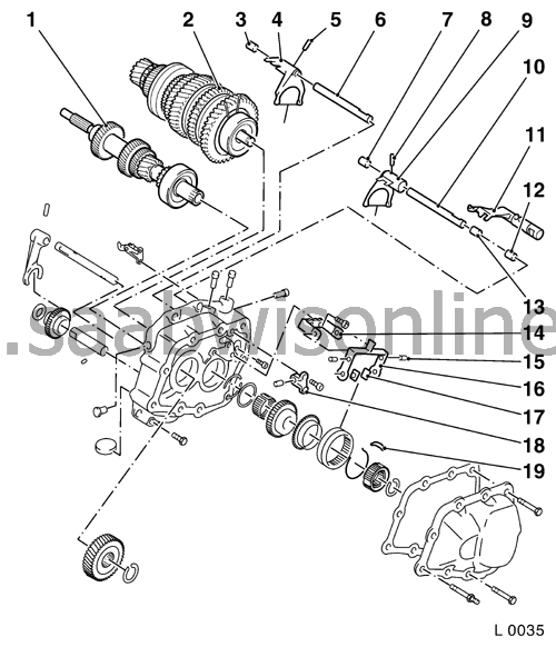
| 1 | Drive shaft |
| 2 | Main shaft |
| 3 | Teflon bushing |
| 4 | Selector fork 1st/2nd gear |
| 5 | Tubular retention pin |
| 6 | Selector rod 1st/2nd gear |
| 7 | Teflon bushing |
| 8 | Tubular retention pin |
| 9 | Selector fork 3rd/4th gear |
| 10 | Selector rod 3rd/4th gear |
| 11 | Selector dog, 5th gear |
| 12 | Teflon bushing |
| 13 | Teflon bushing |
| 14 | Pivot bracket |
| 15 | Pin |
| 16 | Rocker arm |
| 17 | Sliding key |
| 18 | Bridge with interlock pin |
| 19 | Sliding key |
Illustration
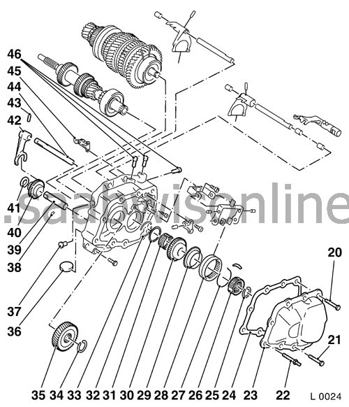
| 20 | Bolt M8 |
| 21 | Bolt M7 |
| 22 | Bolt |
| 23 | Bearing housing cover |
| 24 | Gasket |
| 25 | Circlip |
| 26 | Synchromesh assembly, 5th gear |
| 27 | Synchromesh spring |
| 28 | Synchromesh sleeve, 5th gear |
| 29 | Baulk ring, 5th gear |
| 30 | Gear wheel, 5th gear (driven) |
| 31 | Needle bearing |
| 32 | Circlip |
| 33 | Thrust washer |
| 34 | Circlip |
| 35 | Pinion, 5th gear (driving) |
| 36 | Magnet |
| 37 | Locking plug |
| 38 | Ball |
| 39 | Reverse idler shaft |
| 40 | Idler gear wheel, reverse gear |
| 41 | Thrust washer |
| 42 | Selector fork, reverse gear |
| 43 | Tubular retention pin |
| 44 | Selector rod, reverse gear |
| 45 | Catch |
| 46 | Locking plug |
| To remove |
| Note | ||
|
The gearbox remains in place. |
| 1. |
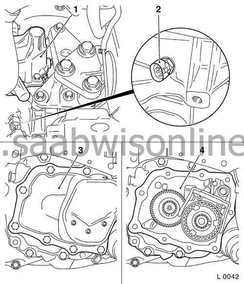
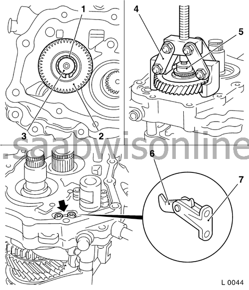
Remove the reversing light switch (2).
|
|
| 2. |
Remove the bearing housing cover (3) - see service procedure
Bearing housing cover gasket, replacement F17
.
|
|
| 3. |
Mount the bearing housing on KM-552 (2) or alternatively
87 92 228 Holder, transmission
. Fit KM-552 on KM-113-2 (1) or alternatively
87 92 228 Holder, transmission
on
78 74 878 Floor stand
|
|
| 4. |
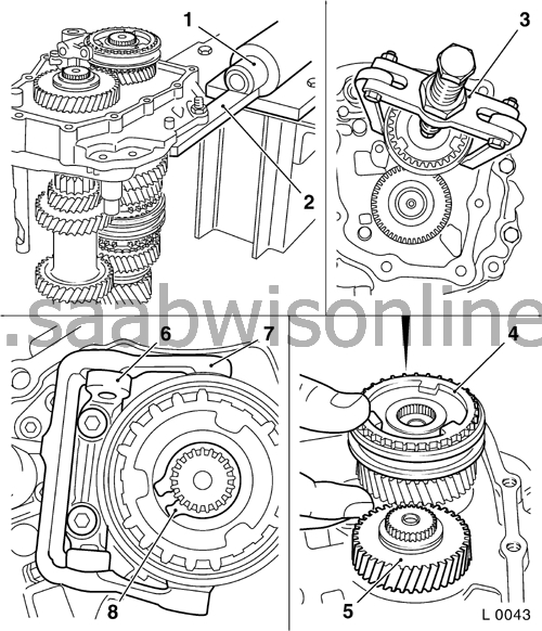
Remove the pivot bracket (6) together with the rocker arm (7) from the bearing housing (2 screws).
Note Micro-encapsulated bolts. If the bolts are difficult to unscrew, warm the bearing housing to about 80 ° C with a warm air gun |
|
| 5. |
Remove the circlip (8) from the synchromesh assembly. Remove the 5th gear synchromesh assembly (4) together with the 5th gear gear-wheel (5) (small) from the main shaft. Use KM-161-B (3) if necessary. Remove both the 5th gear gear-wheel needle cages.
|
|
| 6. |
Remove the circlip(1) from the 5th gear pinion (driving) (2) from the drive shaft (3).
|
|
| 7. |
Fit thrust collar (5) for KM-553-A
( 87 92 913 Puller F17)
(6) on the drive shaft. Pull off the 5th gear pinion from the shaft using KM-553-A (
87 92 913 Puller F17
). Check that KM-553-A is correctly positioned on the 5th gear pinion.
|
|
| 8. |
Remove the pivot bracket (7) together with the catch (6) from the bearing housing - 2 screws (arrowed)
Note Micro-encapsulated bolts. If the bolts are difficult to unscrew, warm the bearing housing to about 80 ° C with a warm air gun |
|
| 9. |
Remove the locking plugs (arrowed) from the bearing housing with KM-727- (2) and KM-328-B (1).
|
|
| 10. |
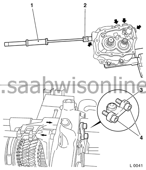
Remove from the bearing housing the screws (4) holding the interlock pin bridge (3).
Note Micro-encapsulated bolts. If the bolts are difficult to unscrew, warm the bearing housing to about 80 ° C with a warm air gun |
|
| 11. |
Engage 2nd and 5th gear (with the selector dog). When 3rd gear is then engaged the bridge is pushed out.
|
|
| 12. |
Reduce the load on the selector rod guide by supporting the rod at the top with a bit of wood (1).
|
|
| 13. |
Tap out the tubular retention pins (arrowed) from the 3rd/4th gear selector fork (3) and the reverse gear selector fork (6) with a 4mm drift.
|
|
| 14. |
Remove the selector rod (2) and the 3rd/4th gear selector fork (3) and the reverse idler shaft (6) from the bearing housing.
|
|
| 15. |
Remove the 5th gear selector dog (4) from the bearing housing.
|
|
| 16. |
Pull out the interlock pin (5) from the bearing housing.
|
|
| 17. |
Remove the 1st/2nd gear selector fork.
Tap out the retention pin (3) from the 1st/2nd gear selector fork (4) with KM-308 Remove the selector fork with the selector rod Warning: Take hold of the main shaft, drive shaft and the reverse-gear pinion. 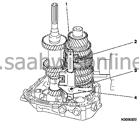
|
|
| 18. |
Remove the main shaft and the drive shaft
Remove the bearing housing from KM-552 Press out the main shaft and drive shaft with KM-6335 (1) as illustrated Note: In order that both shafts may be pressed out evenly, the press anvil must be located more towards the main shaft. Take hold of the main shaft, drive shaft and reverse idler gear Important: Watch out for the detent balls which will be released. 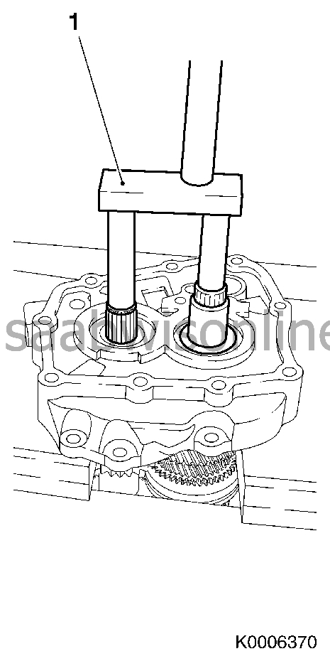
|
|
| 19. |
Remove the reverse idler gear shaft (1)
Hold the reverse idler shaft in a vice with suitable jaw grips Carefully tap the bearing cover with a brass drift 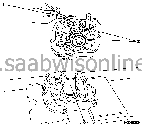
|
|
| 20. |
Remove the main shaft and drive shaft bearings.
2x Remove the circlips (2). 2x Press out the bearings with KM-500-5 or alternatively 87 92 210 Support, differential bearing (3). |
|
| 21. |
Clean all parts and sealing surfaces.
|
|
| 22. |
Check the parts.
Check all parts for wear, pitting or damage. Replace if necessary. |
|
| To fit |
Clean all parts and sealing surfaces.
Check all parts for wear, pitting or damage. Replace if necessary.
Important Wet all the bearing, contact, rubbing and location surfaces of all rotating parts with gearbox oil.
| 1. |
Fit the main and drive shaft bearings
2x Press in the bearing with KM-523-1 (1) and KM-6336 or alternatively 87 92 475 Press sleeve, differential bearing (2) 2x Fit the circlip (3) Caution: Check that the circlips are correctly located. Important: Check that the shafts are correctly located. 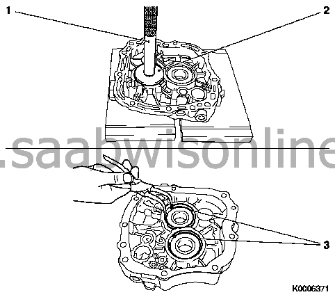
|
|
| 2. |
Fit the main shaft and drive shaft
Place the bearing housing (4) on KM-6338 (5) Position the main shaft (1) and the drive shaft (3) in the bearing housing Caution: Pay attention to the assembly arrangement Press in the main shaft and the drive shaft with KM-6338 and KM-6337 (2) Important: Note the assembly arrangement 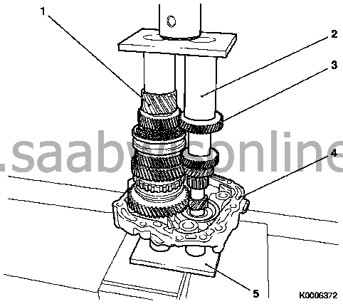
|
|
| 3. |
Fit the reverse idler gear shaft (1)
Put the reverse idler gear on the shaft Caution: Note the orientation, the selector fork track is uppermost. Push the reverse idler gear shaft, with the detent ball (arrowed) inserted, in until it seats in the bearing cover 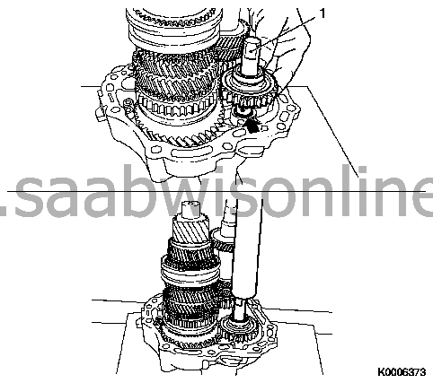
|
|
| 4. |
Fit the 5th gear bearing sleeve (1)
Place the bearing cover on KM-6337 (3) Press the bearing sleeve onto the main shaft with KM-6339 or alternatively 87 91 196 Ring, bearing race (2) 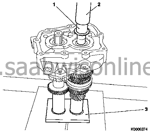
|
|
| 5. |
Fit the bearing housing on KM-113-2
Fit the bearing housing on KM-552 Fit the bearing cover with KM-552 on KM-113-2 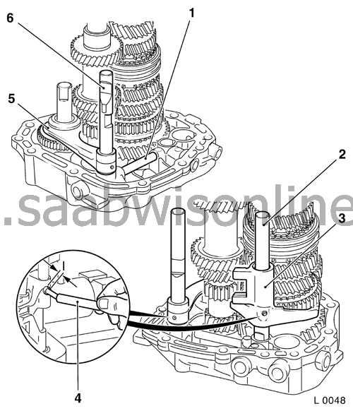
|
|
| 6. |
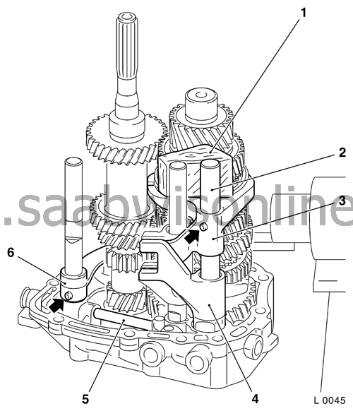
Fit the interlock pin (1)
Insert the pin for the interlock between 3rd/4th gear and reverse gear |
|
| 7. |
Fit the reverse gear selector fork
Important: In order to reduce the loading on the selector rod guide in the bearing house, the selector rods must be supported with a wooden wedge when inserting the pins. Insert the reverse gear selector fork (5) and selector rod (6) Insert a new retention pin with KM-308 or a suitable drift (4) Caution: Let the retention pin stick out about 2 mm (dimension l). |
|
| 8. |
Fit the 1st/2nd gear selector fork
Important: In order to reduce the loading on the selector rod guides in the bearing house, the selector rods must be supported with a wooden wedge when inserting the pins. Insert the 1st/2nd gear selector fork (3) and selector rod (2) Insert a new retention pin with KM-308 or a suitable drift (4) Caution: Let the retention pin stick out about 2 mm (dimension l). |
|
| 9. |
Fit the 5th gear selector dog (4)
|
|
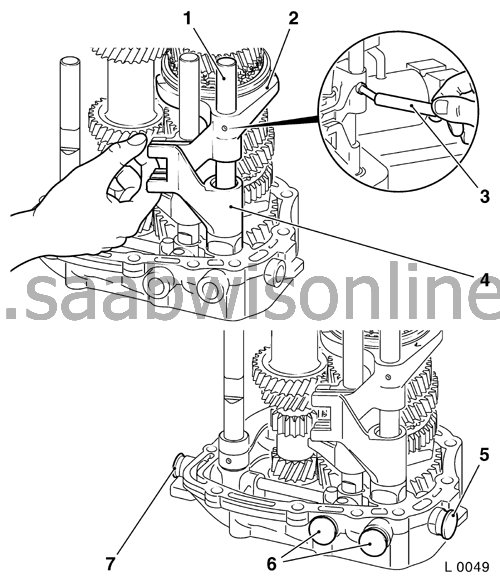
| 10. |
Fit the 3rd/4th gear selector fork
Important: In order to reduce the loading on the selector rod guides in the bearing house, the selector rods must be supported with a wooden wedge when inserting the pins. Fit the 3rd/4th gear selector fork (2) and selector rod (1) Insert a new retention pin with KM-308 or a suitable drift (3) Caution: Let the retention pin stick out about 2 mm |
|
| 11. |
Fit the locking plug
Fit the four locking plugs (5, 6 and 7) Note: Drive them home with a plastic hammer or soft metal drift. |
|
| 12. |
Move the selector forks to the neutral position
|
|
| 13. |
Engage 2nd, 3rd and 5th gears
Note: Turn the bearing housing on its side. |
|
| 14. |
Fit the interlock pin bridge
Position the interlock pin bridge (2) on the bearing housing Fit the two screws (1) with thread locking compound Caution: do not tighten yet. Position the 3rd/4th gear selector fork in the neutral position Tighten the two screws (1) (7 Nm) Move the selector forks to the neutral position 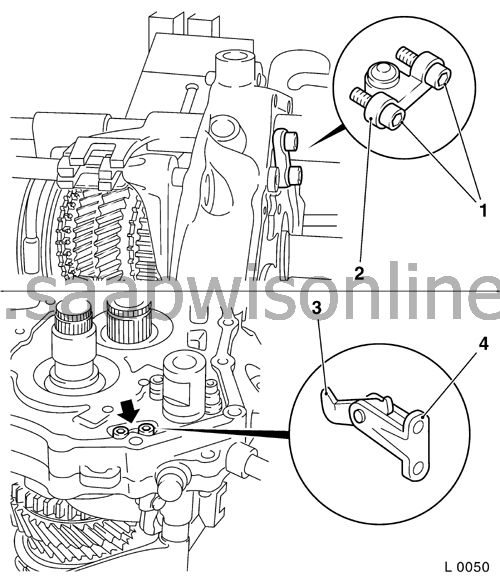
|
|
| 15. |
Fit the pivot bracket (4) with catch (3)
Position the holder Fit the two screws (arrowed) with thread locking compound Tighten the two screws (arrowed) (7 Nm) |
|
| 16. |
Fit the 5th gear pinion (driving) (2)
Important: Note the assembly orientation. The long pinion hub points towards the bearing housing. Fit the bearing housing with main shaft and drive shaft in KM-6337 (3) Press on the 5th gear pinion with KM-334 or alternatively 87 91 196 Ring, bearing race (1) Fit a new circlip (4) Caution: The circlip must be securely snapped into place. |
|
| 17. |
Assemble the 5th-gear gear wheel (5) (driven)
Wet the needle bearings (6) with gearbox oil and put them onto the main shaft Caution: Check that the needle bearings are correctly located. Assemble the 5th-gear pinion and baulk ring on the main shaft 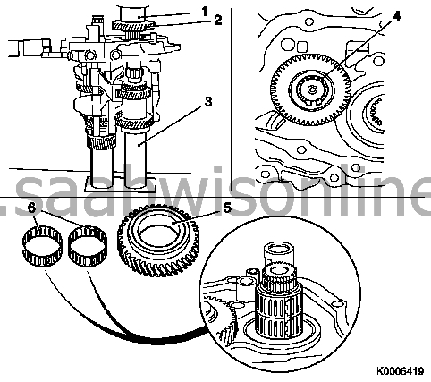
|
|
| 18. |
Press on the 5th gear synchromesh assembly
Put the bearing housing in KM-6337 Put the synchromesh assembly (1) on the main shaft Important: The tabs on the baulk ring must align with the grooves in the synchromesh assembly. Press the synchromesh assembly onto the main shaft using KM-334 or a suitable sleeve Fit a new circlip (2) Caution: The circlip must be securely snapped into place. 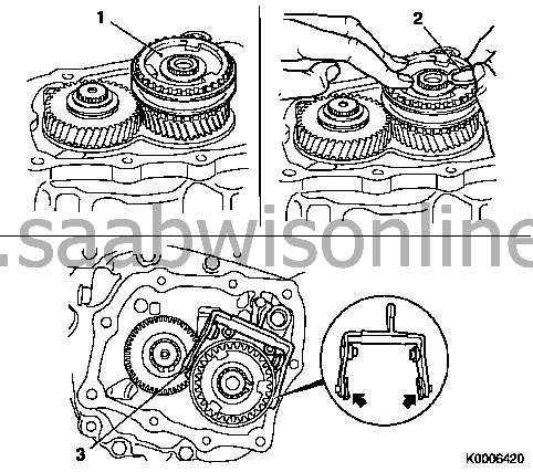
|
|
| 19. |
Fit the pivot bracket with rocker arm
Fit the two sliding keys (arrowed) onto the rocker arm (3) (5th gear selector fork) Put the pivot bracket with rocker arm onto the bearing housing Fit the two screws with thread locking compound 2x Tighten the screws (22 Nm) |
|
| 20. |
Fit the thrust washer (arrowed) to the reverse idler shaft with grease
Fit the thrust washer with grease Important: Before the bearing housing is assembled to the gearcase the mounting and positioning of the following components should be checked: Selector fork, 3rd/4th gear (1), Selector rod, 3rd/4th gear (2), Selector dog, 5th gear (3), Selector rod, 1st/2nd gear (4), Selector fork, 1st/2nd gear (5), Interlock pins (6), Selector fork, reverse gear (7), Selector rod reverse gear (8) 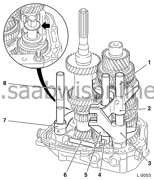
|
|
| 21. |
Remove the bearing housing from KM-113-2
Remove the bearing housing from KM-552 |
|
| 22. |
Fit the bearing housing cover (2)
See Bearing housing cover gasket, replacement F17 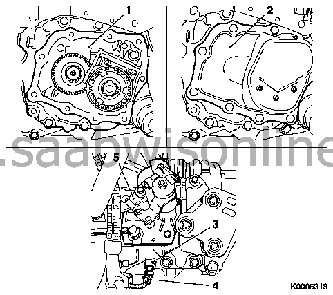
|
|
| 23. |
Fit the gear change cover (5)
See the service procedure " Gear change cover, removal and fitting and/or sealing (F 17)" |
|
| 24. |
Gearbox oil level, checking and adjusting
|
|
| 25. |
Fit the reversing light switch (3)
Assemble with a new sealing ring Tighten the reversing light switch (20 Nm) Replace the wiring loom connector (4) |
|
| 26. |
Check the gear change function
Check that the gears may be freely engaged whilst the vehicle is stationary, the engine running and the clutch disengaged |
|
