Automatic transmission assembly
|
|
Automatic transmission assembly
|
|
1.
|
Place drapes over the wings to keep the paintwork clean and protect it from damage.
|
|
2.
|
Remove the upper engine cover.

|
|
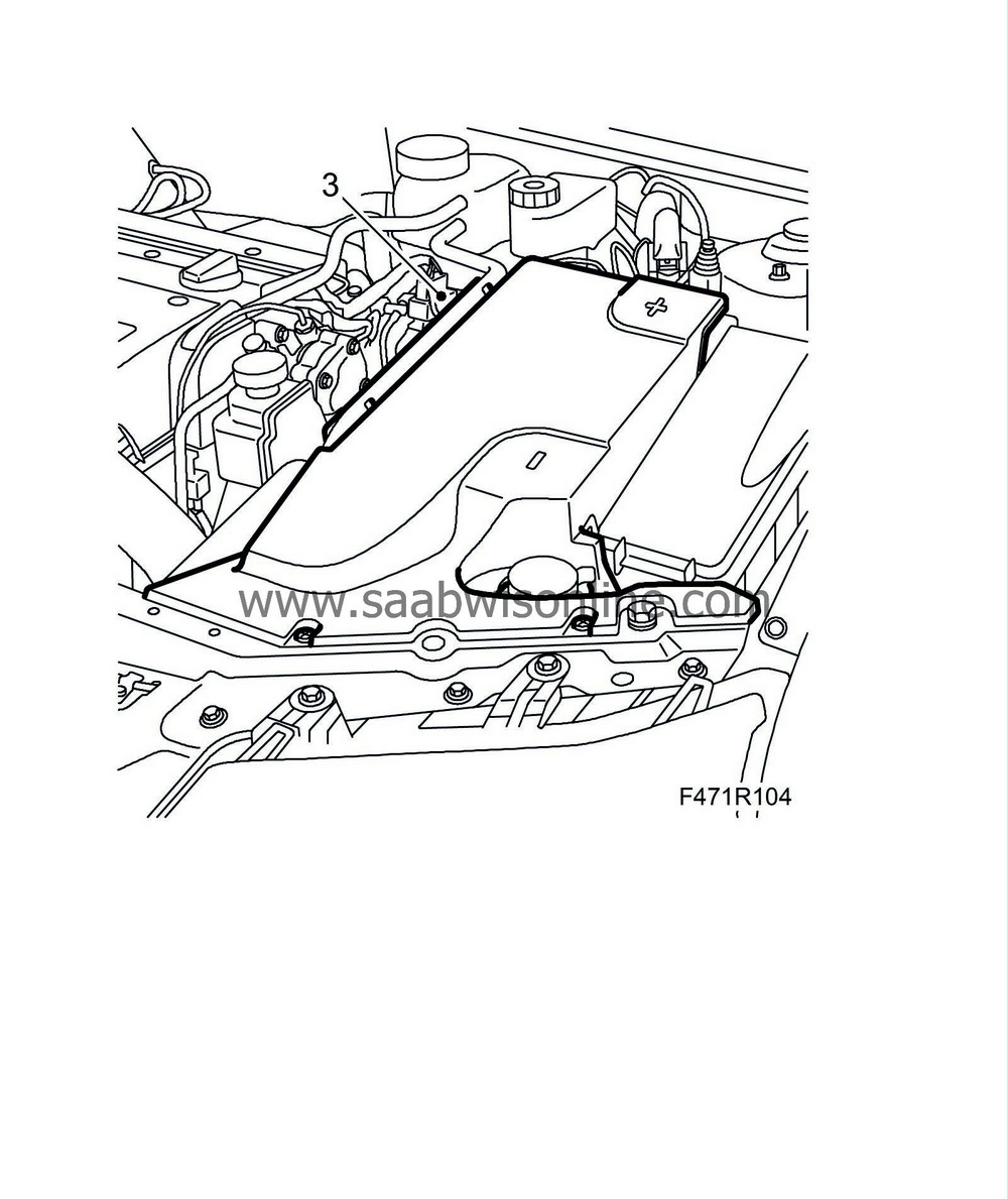
3.
|
Remove the battery cover.
|
|
4.
|
Disconnect the battery terminals and remove the battery and cooling pipe. Undo the cable clamp under the battery tray.

|
|
5.
|
D223L:
Remove the cover with vacuum tank, etc., and bend aside the cover. Press in the catch, detach the power steering fluid reservoir with bracket and move aside.
|
|
6.
|
Disconnect the bonnet switch.
|
|
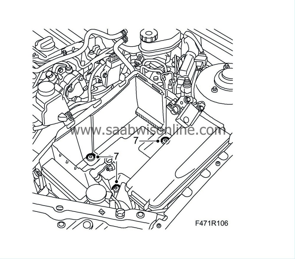
7.
|
Remove the battery tray.
|
|
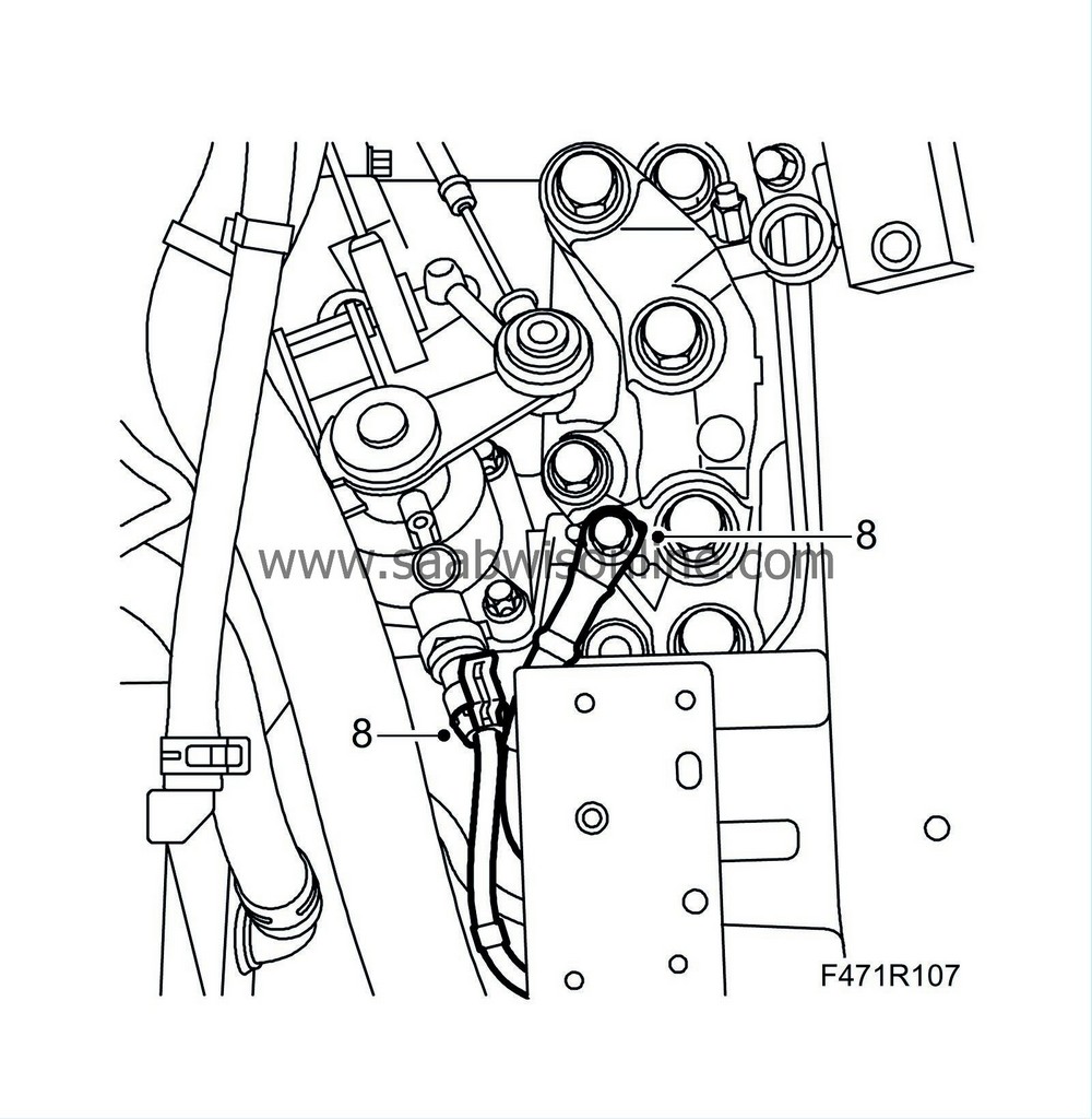
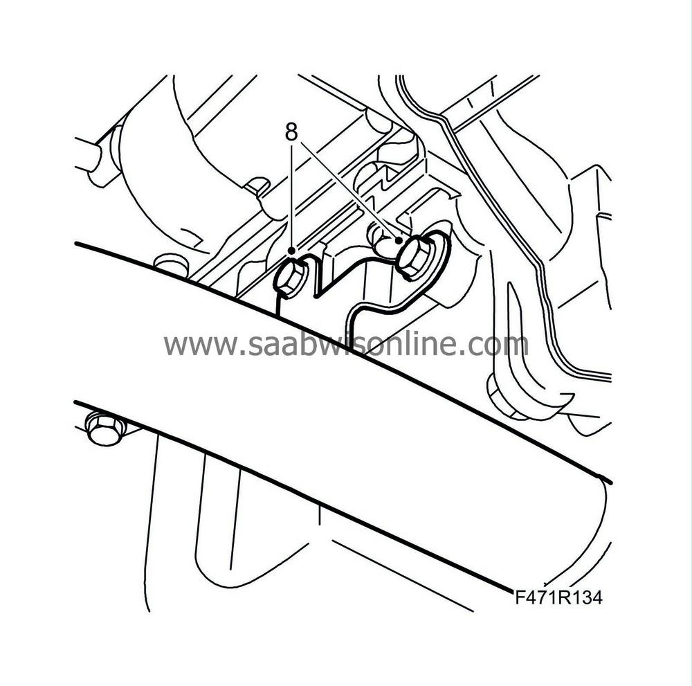
8.
|
Disconnect the ground cable from the engine bracket and the reversing light switch connection.
|
|
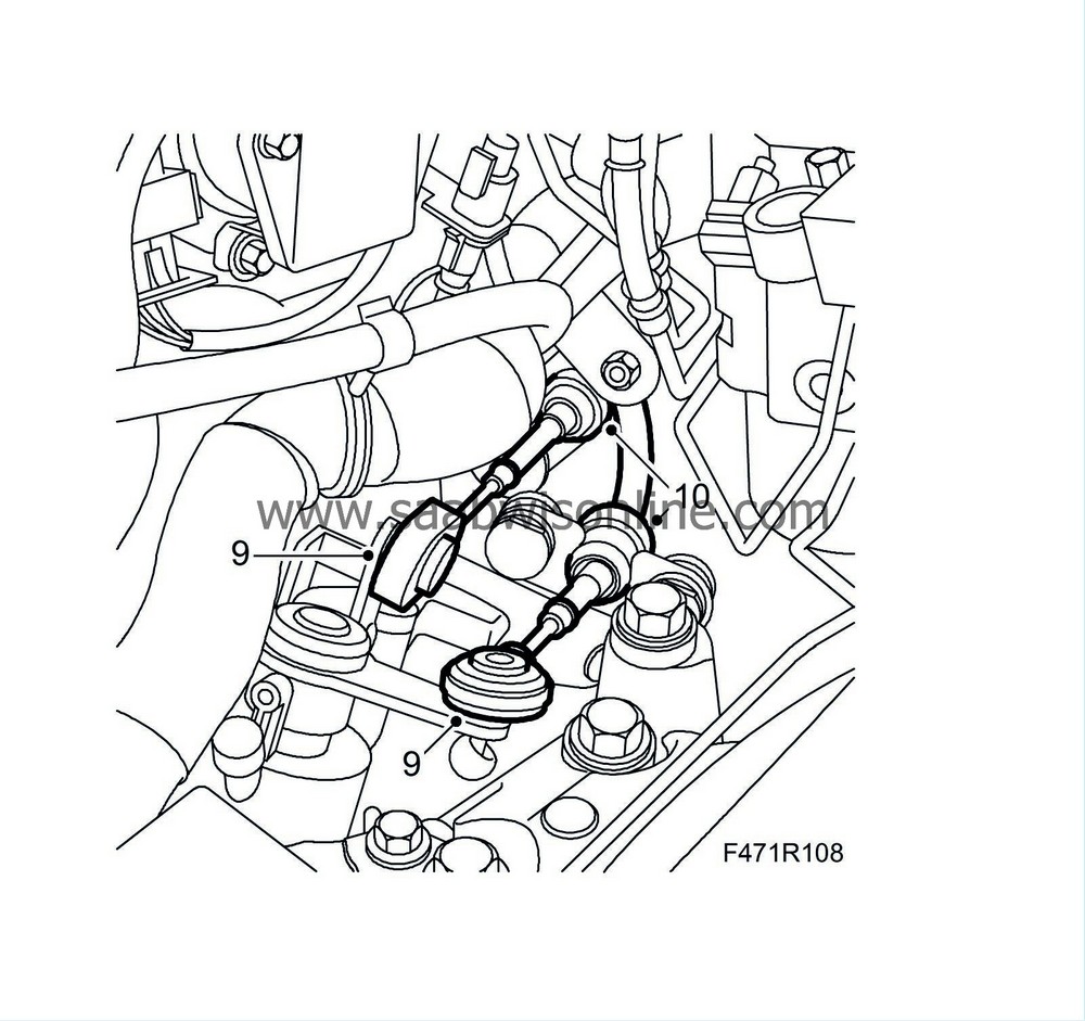
9.
|
Remove the gear cables from the gearbox by pulling the locking sleeves back.
|
|
10.
|
Lift up the cables from the levers.
|
|
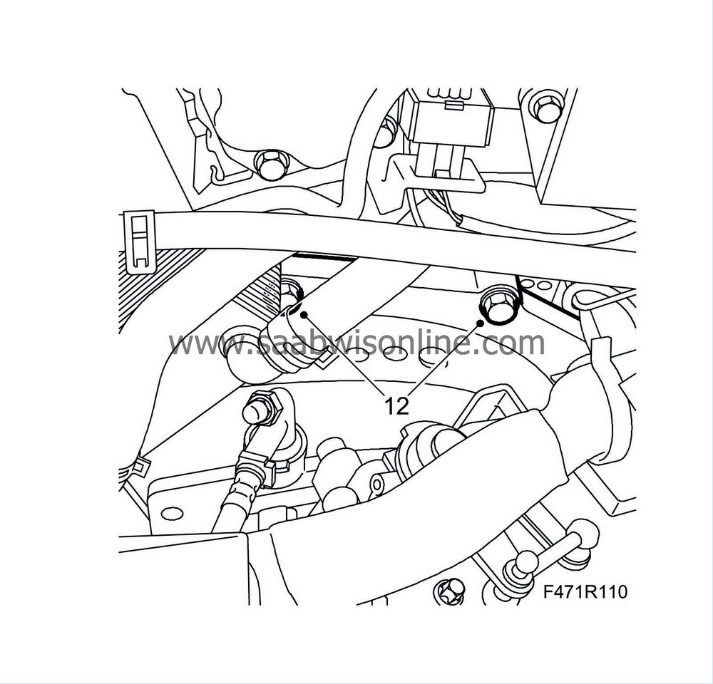
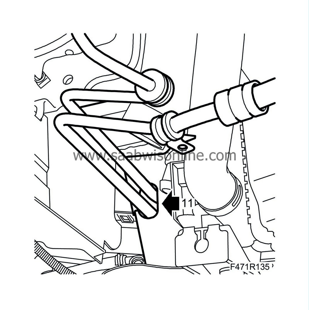
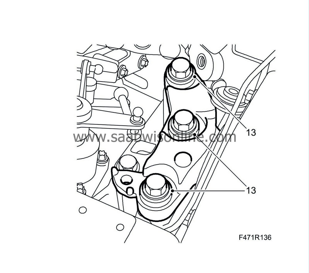
12.
|
Remove the upper gearbox bolts.
D223L:
The bolt for the starter motor is longer than the other two.
|
|
13.
|
Remove the coolant reservoir.
|
|
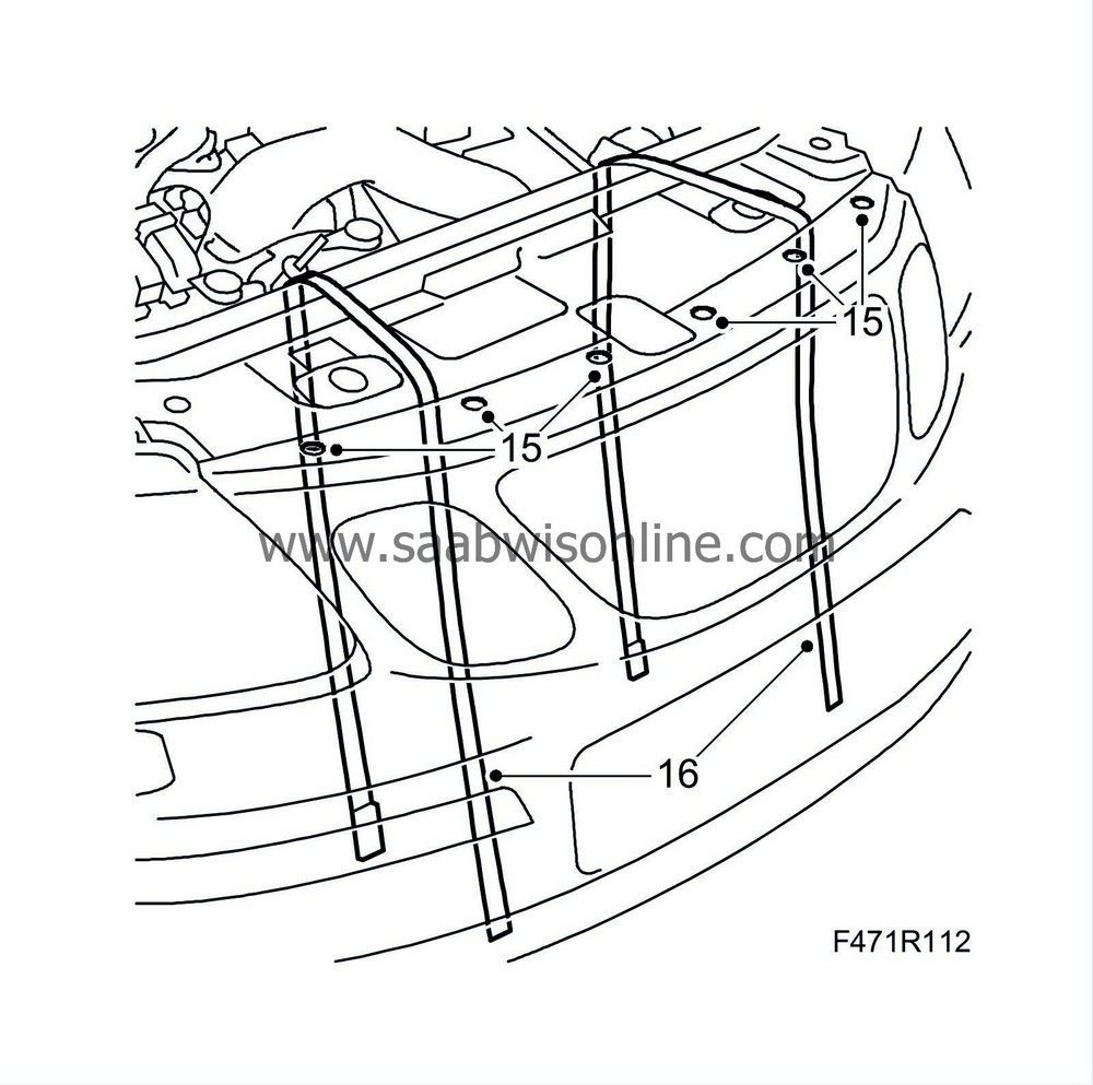
15.
|
Undo the upper bumper shell mountings.
|
|
16.
|
Suspend two
83 95 212 Strap
in place above the radiator core so they are accessible from below.
|
|
18.
|
Remove the front wheels.
|
|
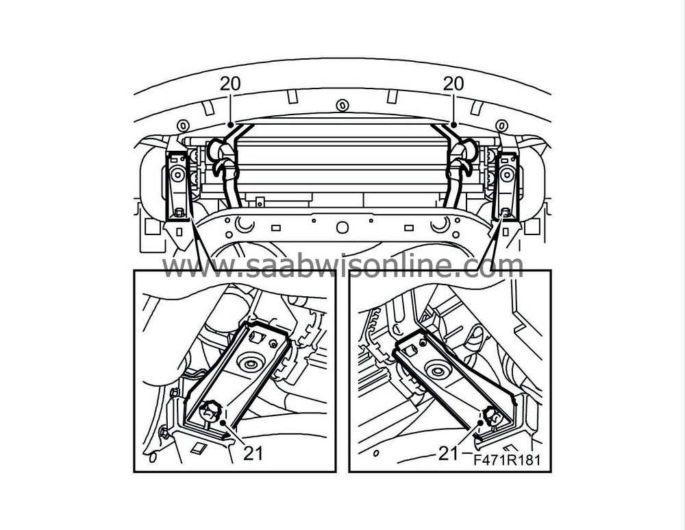
20.
|
Secure the radiator core with the straps.
|
|
21.
|
Remove the radiator brackets from the subframe.
|
|
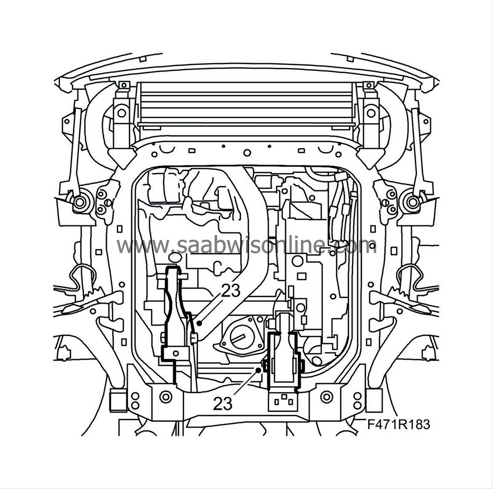
23.
|
Remove the engine torque rod from the subframe.
|
|
24.
|
Remove the bolt and nut holding the suspension arm to the steering swivel member on both sides.
|
|
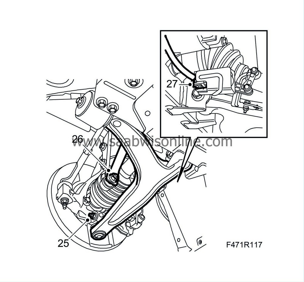
25.
|
Detach the anti-roll bar from the link arm.

|
|
26.
|
Unplug the connector and detach the cable clip of the headlamp angle sensor (option)
|
|
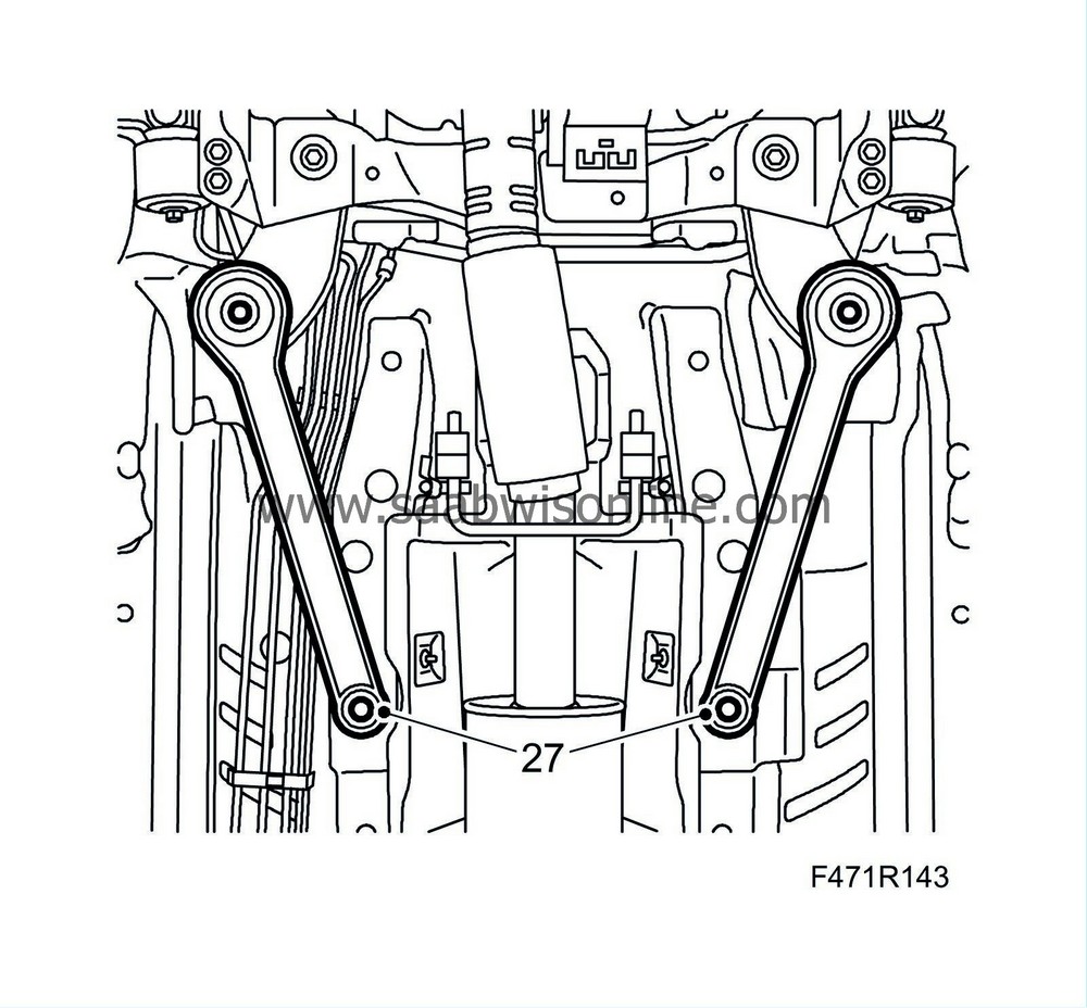
27.
|
Remove the steering gear from the subframe.
|
|
28.
|
Put the nuts and washers in a safe place. Let the steering gear hand in place.
|
|
29.
|
Remove the clamps holding the power steering pipe from the subframe.

|
|
30.
|
Detach the front part of the wing liner and bend it slightly out of the way.

|
|
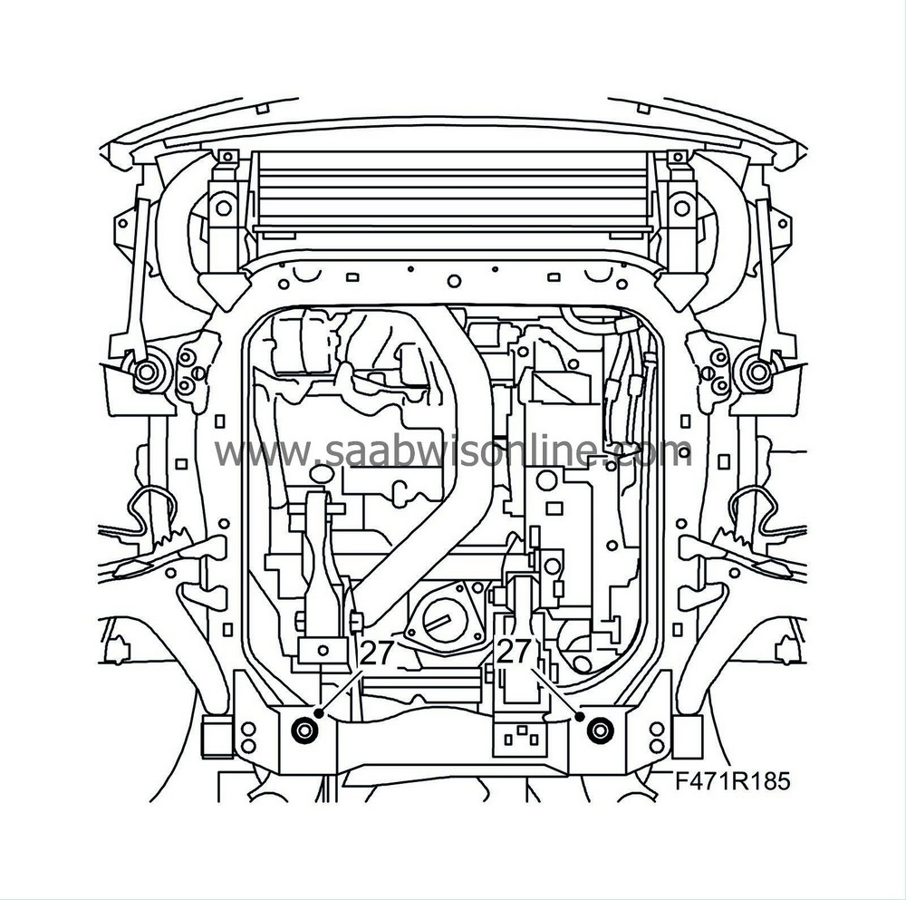
32.
|
Remove the subframe bolts and the rear brackets.
|
|
33.
|
Lower the subframe slightly.
|
|
34.
|
Remove the anti-roll bar from the subframe, protect the steering gear boot. Fit the link arm nuts loosely so the anti-roll bar is kept hanging in place.
|
|
35.
|
Pull out the steering arm ball joints from the steering swivel members.
|
|
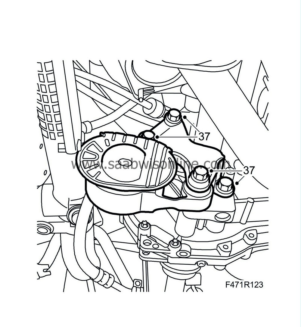
37.
|
Remove the torque rod bracket. Undo the bolt for the torque rod for easier fitting.
|
|
38.
|
Place a receptacle under the car, remove the level plug and the drain plug. Drain the gearbox oil. Refit the drain plug.
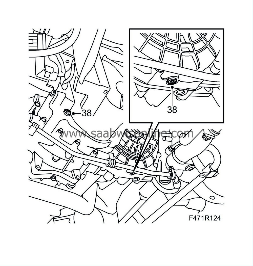
Tightening torque 50 Nm (37 lbf ft)
|
|
39.
|
D223L:
Remove the bolts from the coolant pipe bracket and move aside.
|
|
40.
|
Remove the bolts in the charge air pipe bracket and move away the pipe.

|
|
41.
|
Remove the lower transmission bolts. Leave one bolt in place loose.

|
|
42.
|
Disconnect the ground lead.

|
|
45.
|
Lower the car, mark the positions of the bolts on the left-hand engine bracket with a marker pen for correct refitting and then remove the bolts from the mounting.

|
|
46.
|
Lower the drive unit approx. 70 mm from the lifting beam to facilitate the removal of the gearbox. Measure the distance at the left-hand engine mounting.
|
|
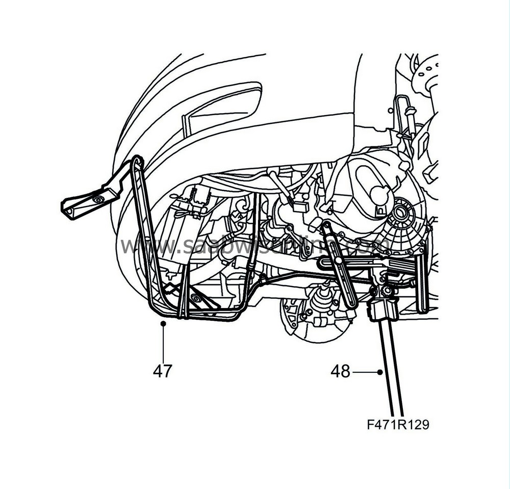
47.
|
Raise the car and move aside the power steering cooling coil. Hang it up with
83 95 212 Strap
.
|
|
48.
|
Fit
87 92 608 Holder for single-column lift
onto a column jack. Adjust and secure the tool in the transmission as illustrated. Use bolts of 8.8 grade that are about 20 mm longer than the bolts that were removed.
|
|
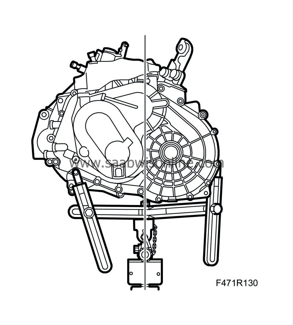
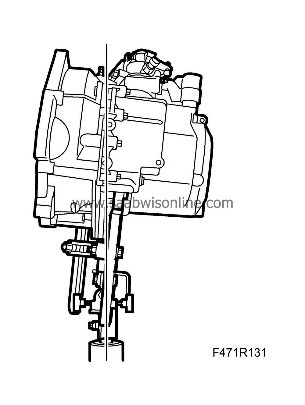
49.
|
Remove the last bolt, pull out the transmission and lower it.
|
Important
|
|
The jack can tip over. Be careful.
|
|
|
|
|
50.
|
Lift the transmission down from the column jack with an engine lift and
87 92 442 Lifting cable
while undoing the lifting tool from the transmission.
|
|
3.
|
Lubricate the guide sleeves on the engine with anti-corrosion agent.
|
|
4.
|
Fit
83 95 162 Protective collar, drive shafts
in the right shaft seal in the transmission. This is done to protect the seal while the transmission is being fitted. Lubricate the seal.

|
Important
|
|
Always replace the shaft seals in the gearbox. Lubricate with gearbox oil.
|
|
|
|
|
5.
|
Fit the gearbox with the lifting tool on the column jack.
|
Important
|
|
Make sure the gear cables are positioned correctly when lifting the gearbox.
|
|
|
|
Important
|
|
Slide in the gearbox until approx. 20 mm are remaining and remove the tool 83 95 162.
|
|
|
|
|
6.
|
Push in the rest of the gearbox. Turn the crankshaft if necessary to get the gearbox in place.
|
|
7.
|
Tighten all bolts except the top one between the engine and the gearbox.

Tightening torque, M10 bolts 40 Nm (30 lbf ft)
Tightening torque, M12 bolts 70 Nm (52 lbf ft)
|
|
8.
|
D223L:
Fit the coolant pipe bracket.
All:
Fit the charge air pipe bracket.
|
|
9.
|
Remove the lifting tool from the gearbox and move away the jack.
|
|
10.
|
Refit the gearbox bolts.
Tightening torque 24 Nm (18 lbf ft)
|
|
11.
|
Undo the strap and position the power steering cooling coil in place. Make sure it is fitted on the correct side of the rubber seal.
|
|
12.
|
Lower the car. Lift in place the power train with the lifting beam until it meets the engine mounting.
|
|
13.
|
Fit the bracket for the engine mounting according to the marks made earlier.
Tightening torque 70 Nm +45° (52 lbf ft +45°)
|
|
14.
|
D223L:
Remove the lifting beam.
B207:
Remove the holder, lifting beam and lifting eyes.
|
|
15.
|
Fit the coolant reservoir.
|
|
16.
|
Fit the upper gearbox bolts.
D223L:
The bolt for the starter motor is longer than the other two.

Tightening torque 70 Nm (52 lbf ft)
|
|
18.
|
Fit
83 95 162 Protective collar, drive shafts
in the left drive shaft seal. Remove the strap. Make sure that the drive shaft is clean, lubricate it and then align it with the tool.

|
Important
|
|
Fit the driver in the gearbox until approx.20 mm are remaining and pull out the tool before the sealing surface of the shaft reaches the shaft seal.
|
|
|
|
|
19.
|
Push in the rest of the drive shaft into the gearbox until the circlip clicks in.
|
|
20.
|
Attach the ABS cable to the clip.
|
|
21.
|
Fit the ground cable.
|
|
23.
|
Fit the torque rod bracket.

|
|
25.
|
Undo the link arm nuts and fit the anti-roll bar to the subframe.
Tightening torque 18 Nm (13 lbf ft)
|
|
26.
|
Fit the suspension arm ball joints to the steering swivel member.

Tightening torque 50 Nm (37 lbf ft)
|
Important
|
|
Ensure that the steering knuckle stub is visible on the top of the steering knuckle housing before the bolt is fitted.
|
|
|
|
|
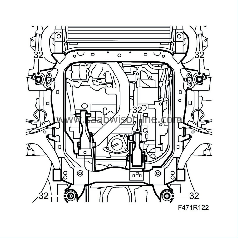
27.
|
Check that the guide pins fit into the reference holes, adjust the subframe until the guide pins go in easily and fit the subframe bolts and brackets.

Tightening torque, subframe: 75 Nm +135° (55 lbf ft +135°)
Tightening torque, rear subframe bolts: 90 Nm +45° (66 lbf ft +45°)
|
|
28.
|
Fit the anti-roll bar link arms. Use a small open spanner.

Tightening torque 64 Nm (47 lbf ft)
|
|
29.
|
Connect the connector and the cable clip to the headlamp angle sensor (optional).
|
|
30.
|
Move away the trolley lift and jig.
|
|
31.
|
Fit the torque rods to the subframe.

Tightening torque 70 Nm +90° (52 lbf ft +90°)
|
|
33.
|
Fit the radiator brackets to the subframe. Remove the straps.

Tightening torque 47 Nm (35 lbf ft)
|
|
34.
|
Fit the clamps holding the power steering pipe to the subframe.

|
|
35.
|
Fit the steering gear to the subframe.

Tightening torque 50 Nm + 60° (37 lbf ft + 60°)
|
|
36.
|
Fit a sleeve clamp to the front exhaust pipe and fit the front exhaust pipe to the catalytic converter. Grease the threads with
30 20 971 Screw-thread paste
. Use a new seal and a new nut.
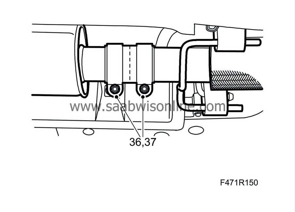
Tightening torque: 25 Nm (18 lbf ft)
|
|
37.
|
Adjust the joint clamp so that the pipe ends are in the middle of the clamp.
|
|
38.
|
Tighten the nuts on the joint clamp.
Tightening torque 40 Nm (30 lbf ft)
|
|
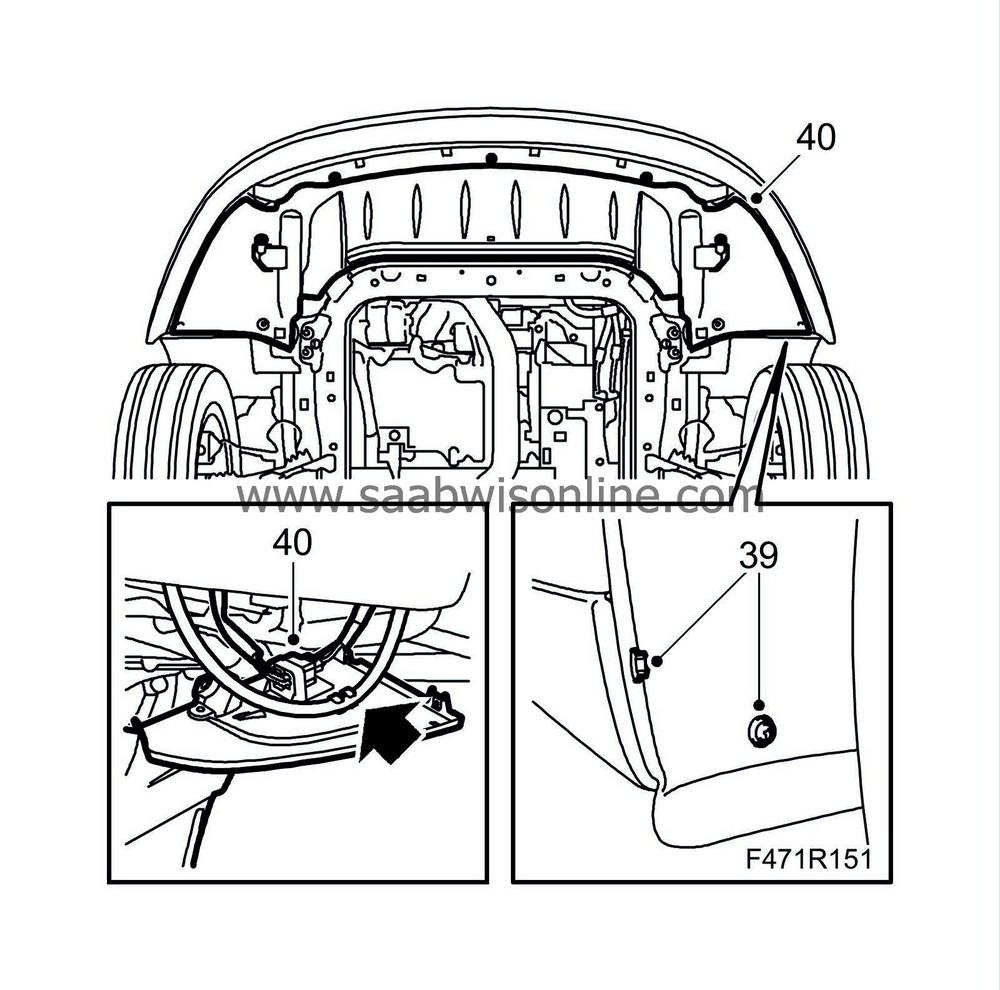
39.
|
Fit the front wing liner section.
|
|
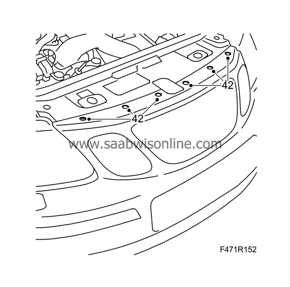
42.
|
Lower the car and fit the bumper shell upper mountings.
|
|
43.
|
Check that the upper radiator guides engage their brackets.
|
|
44.
|
Fit the quick-release coupling to the clutch slave cylinder. Remove the hose pinch-off pliers. Make sure the connection is secured in the correct position.

|
|
46.
|
Attach the gear cables to the gearbox.

|
|
48.
|
Fit the reversing light switch connection and the ground cable to the engine mounting.
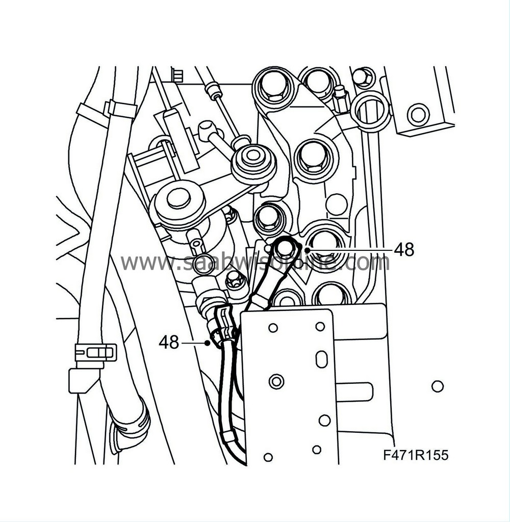
Tightening torque 18 Nm (13 lbf ft)
|
|
49.
|
Fit the battery tray and the bonnet switch connector.

|
|
50.
|
D223L:
Fit the power steering fluid reservoir with bracket and the cable clamp under the battery tray.
|
|
51.
|
D223L:
Fit the cover with vacuum tank, etc.
|
|
52.
|
Fit the cooling pipe and the battery.

|
|
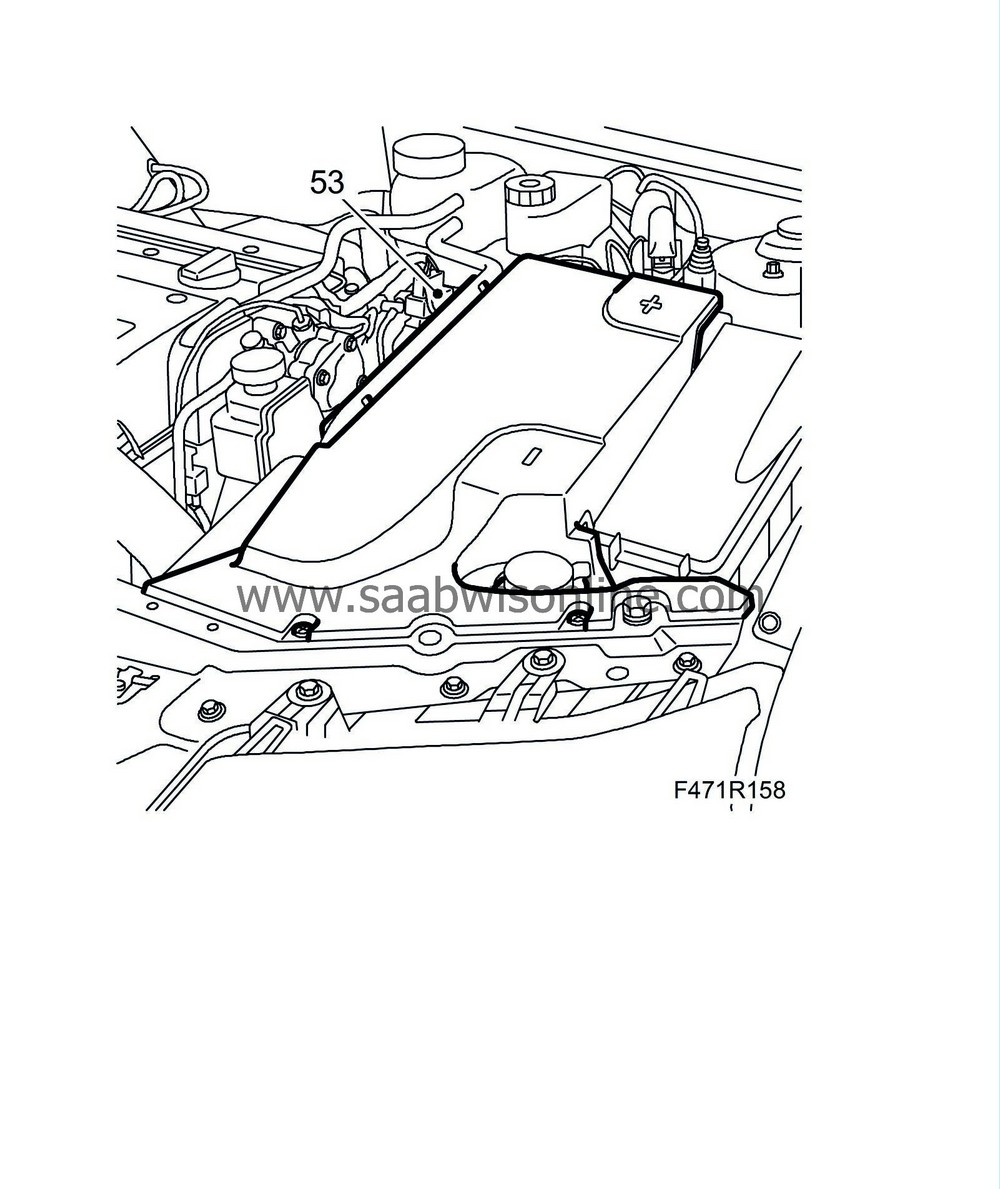
53.
|
Fit the battery cover.
|
|
54.
|
Fit the upper engine cover.

|
|
55.
|
Remove the wing covers.
|
|
57.
|
Test drive the car. Check the position of the steering wheel when driving straight ahead on a level road. Adjust if needed.
|


