PRE-RELEASE
Cylinder head, removing and fitting
| Cylinder head, removing and fitting |
| To remove |
Remove the engine protection cover.
| 1. |
Open the bonnet
|
|
| 2. |
Disconnect the battery.

|
|
| 3. |
Remove the engine protection cover.
Unscrew the lid on the oil filler connection 2x Unscrew Screw on the lid on the oil filler connection |
|
| 4. |
Remove the air cleaner casing (1)
Pull off the cable set connector (2) - Heating conductor-mass air flow sensor Undo the cable set (arrows) Detach the engine ventilation hose (3) Detach the intake hose (4) 
|
|
| 5. |
Undo the front right wheel
5x Undo bolt |
|
| 6. |
Raise the car
|
|
| 7. |
Remove the right front wheel.
5x Undo bolt |
|
| 8. |
Raise the car
|
|
| 9. |
Remove the right wing liner.

|
|
| 10. |
Remove the multi-belt
Turn the multi-belt tension device in the direction of the arrow- Use KM-913-A or a 15mm flex-head spanner (2) Insert KM-6130 or a 4.5mm drift (1) Mark the direction of rotation 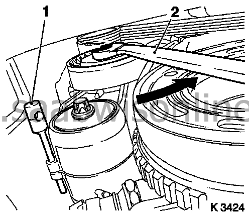
|
|
| 11. |
Remove the multi-belt tension device
Tighten the multi-belt tension device Remove KM-6130 (2) or drift. Undo the multi-belt tension device Undo the bolt (1) 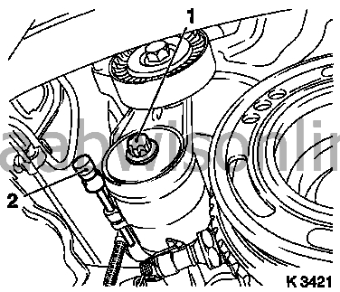
|
|
| 12. |
Remove the crankshaft multi-belt pulley
Prise loose the front screw plug from the oil pan Use KM-911 ( 83 96 327 Holder tool, fixing of flywheel ) Undo the bolt Remove KM-911 
|
|
| 13. |
Remove the exhaust system
Important: When removing the middle silencer, a catalytic converter, an exhaust manifold or an exhaust manifold with catalytic converter, the components of the exhaust system remaining on the car must be supported to stop them hanging. The exhaust system component with the flexible pipe can be fastened to the underbody using a suitable object, e.g. steel wire. If the flexible pipe bends 5 - 10 degrees from its intended mounting position there may be damage caused and complete failure of the flexible pipe. Remove the front exhaust pipe - 3x Unscrew nut |
|
| 14. |
Remove the exhaust system.
Instruction: 2 technicians are needed Undo the exhaust system. |
|
| 15. |
Dismantle the engine management system cable set
3x Pull off cable set connector - Oil pressure switch (1), crankshaft sensor (2), dynamic oil level check sensor (3) Undo the cable set 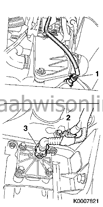
|
|
| 16. |
Remove the intake manifold support
Undo the screw at the top Undo the screw at the bottom |
|
| 17. |
Undo the generator
Undo the nut |
|
| 18. |
Lower the car
|
|
| 19. |
Remove the top part of the tooth belt cover
3x Unscrew (1) Detach from the rear tooth belt cover 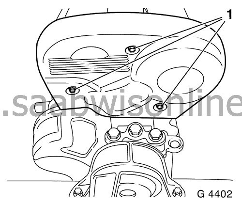
|
|
| 20. |
Remove the bottom of the tooth belt cover
Undo the bolt (arrow) Detach from the rear tooth belt cover 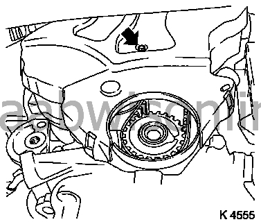
|
|
| 21. |
Remove the camshaft sensor (2)
2x Unscrew Unscrew the nut from the fuel line holder Unscrew the stud Pull off the camshaft sensor cable set connector (1) - Undo the cable set connector 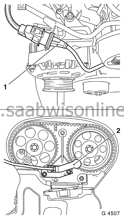
|
|
| 22. |
Set ignition TDC cylinder 1. Screw in the screw for the crankshaft multi-belt pulley
Set the crankshaft to the mark - Turn the crankshaft at a steady rate. Instruction: The markings on the tooth belt pulley and rear tooth belt cover must correspond (III) Fix the camshaft sprockets. Instruction: The markings must be in line with each other and correspond with the top of the cylinder head (I) - Use KM-852 (II) 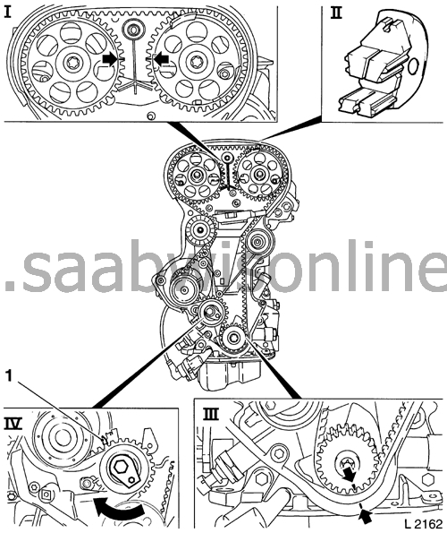
|
|
| 23. |
Remove the tooth belt
Undo the tooth belt tensioning pulley (IV) - Undo the bolt - Turn the setting eccenter in the direction of the arrow (clockwise) until the pointer(1) on the tooth belt tensioning pulley is just short of the left-hand end position. |
|
| 24. |
Remove KM-852 (
83 96 319 Holder tool, fixing of camshaft sprocket Z18XE)
|
|
| 25. |
Remove the intake side tooth belt guide roller (1)
Undo the bolt 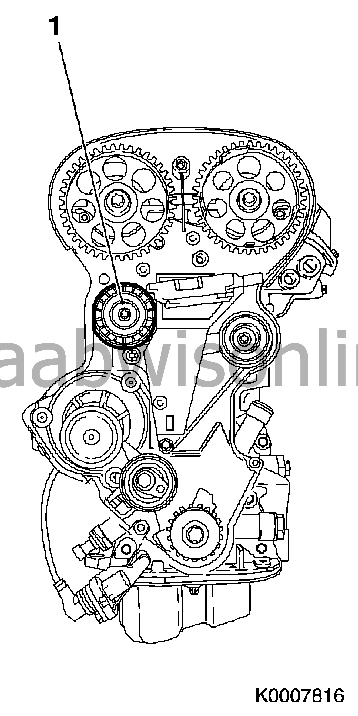
|
|
| 26. |
Drain the coolant
Place a receptacle underneath Open the drain screw (arrow) 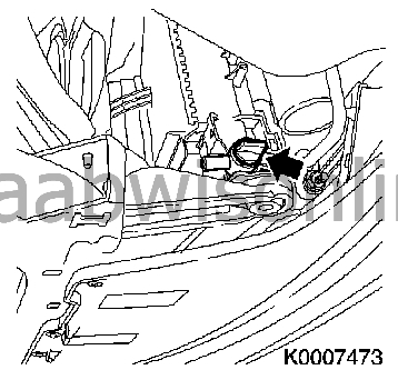
|
|
| 27. |
Lower the fuel pressure
Use 83 94 744 Adapter, fuel pressure gauge Unscrew the test connector protective collar on the fuel rail 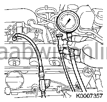
|
||||||||||||||||||||||||
 Warning
| 28. |
Remove the fuel line
from the fuel rail 
|
|
| 29. |
Dismantle the engine management system cable set
Remove the engine vent hose - Undo the clamp 13x Pull off the cable set connector - Air conditioning pressure sensor (10), compressor (9), coolant temperature sensor (8), fuel evaporation valve, throttle valve module (1), solenoid valve switch throttle, 2x engine control modules (2), knock sensor (3), combination connector (4), lambda sensor, fuel regulator (7), DIS ignition module (6). Remove the nozzles' cable duct - Undo the bolt Remove the ground cable. Remove the cable set 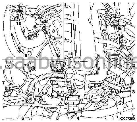
|
|
| 30. |
Remove the DIS ignition module
5x Undo bolt Remove the DIS ignition module Use KM-6009 ( 83 96 335 Removal tool, ignition discharge module Z18XE ) (1) Instruction: Do not pull out crooked 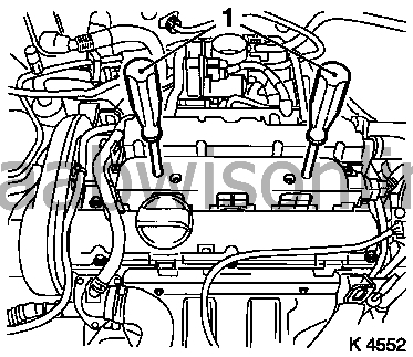
|
|
| 31. |
Remove the DIS ignition module
5x Undo bolt Remove the DIS ignition module - Use KM-6009 (83 96 335 Removal tool, ignition discharge module Z18XE) (1) Instruction: Do not pull out crooked |
|
| 32. |
Remove the camshaft cover.
Remove the throttle valve module preheating line- 2x Undo bolt - Undo the clamp Undo the cable set for the fuel regulation lambda sensor 10x Undo bolt Remove the seal |
|
| 33. |
Pull off the fuel evaporation hose
Use KM-796-A. Undo the generator Undo the bolt Swing back the generator |
|
| 34. |
Remove the exhaust side camshaft sprocket
Undo the bolt - Hold the camshaft hexagon 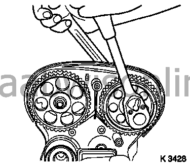
|
|
| 35. |
Remove the inlet side camshaft sprocket
Undo the bolt - Hold the camshaft hexagon |
|
| 36. |
Undo the rear tooth belt cover
2x Unscrew |
|
| 37. |
Remove the hot water return hose
from the intake manifold Undo the holder |
|
| 38. |
Detach the brake servo vacuum line
From intake manifold |
|
| 39. |
Remove the intake manifold
Remove the throttle valve preheating return hose - Undo the clamp 7x Undo the bolt (arrows) Remove the seal 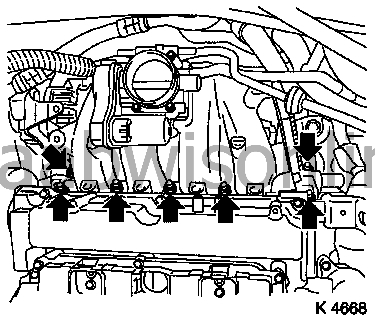
|
|
| 40. |
Detach the coolant pipe (3)
Undo the bolt 2x Detach the clamp from the coolant connection(1), coolant pump (2) 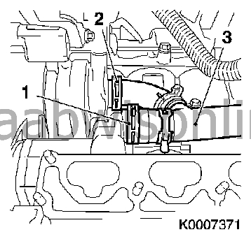
|
|
| 41. |
Remove the coolant hose at the top
from the thermostat housing Undo the clamp |
|
| 42. |
Remove the exhaust manifold protective shield
3x Unscrew |
|
| 43. |
Remove the exhaust manifold
10x Unscrew nut - Remove the engine transport bracket Remove the seal 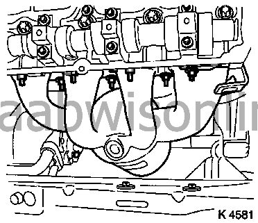
|
|
| 44. |
Undo the holder for the dipstick guide tube
Remove the cable set holder - Undo the bolt Undo the bolt |
|
| 45. |
Remove the cylinder head bolts
10x Undo bolt. Instruction: Undo the bolts in the illustrated order - Undo bolts (90°) - Undo bolts (180°) Important: Place the cylinder head on suitable wood blocks 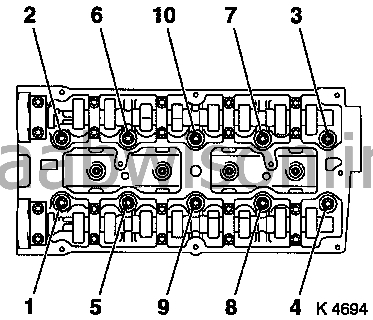
|
|
| 46. |
Remove the cylinder head. Instruction: 2 technicians are needed
Remove the cylinder head gasket |
|
| 47. |
Clean the sealing surfaces.
cylinder head, engine block, exhaust manifold, intake manifold, camshaft cover |
|
| 48. |
Check flatness
Important: The cylinder head must not be refaced. Measure the height of the cylinder head with a steel rule and feeler gauge - Sealing surface to sealing surface: 135.85 - 136 mm (dim l) 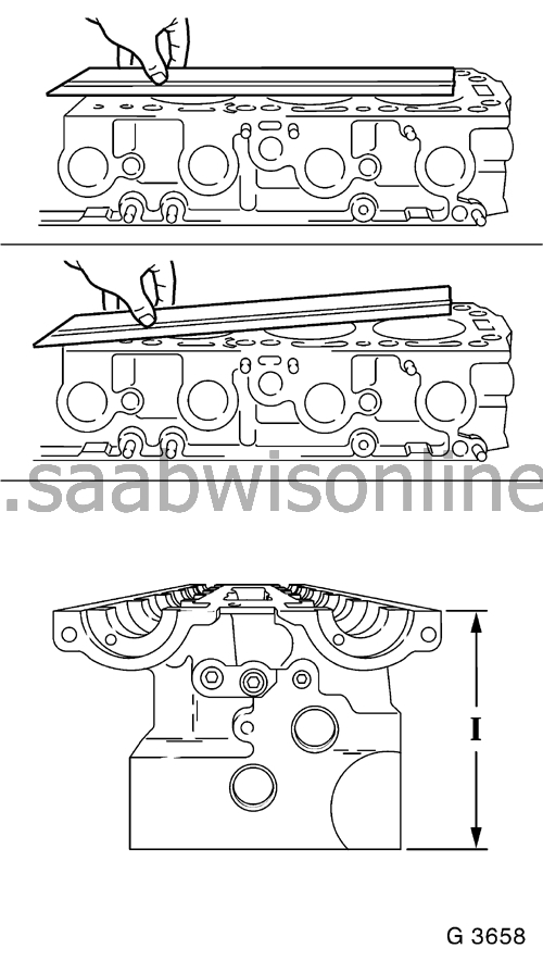
|
|
| 49. |
Change the cylinder head gasket
Put on the cylinder head gasket Instruction: OBEN / TOP must be face up |
|
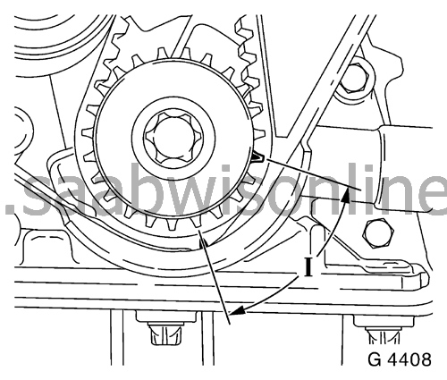
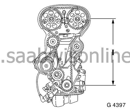
| 50. |
Put the crankshaft to 60° (dim I) before ignition TDC
|
|
| 51. |
Put in place the cylinder head
Instruction: 2 technicians are needed |
|
| 52. |
Fasten the cylinder head
Instruction: Change the cylinder head bolts 10x Screw the cylinder head bolt tight 10x Tighten cylinder head bolt - Tightening torque 25 Nm + 90° + 90° + 90° + 45° Instruction: Observe the tightening order! 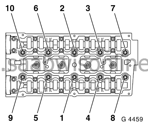
|
|
| 53. |
Fasten the holder for the oil dipstick guide tube
Fit the cable set holder - Tighten the bolt - Tightening torque 8 Nm Tighten the bolt - Tightening torque 8 Nm 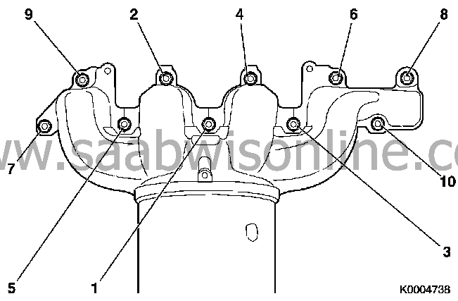
|
|
| 54. |
Fit the exhaust manifold
Change the seal 10x Change nut Put in place the engine transport bracket Important: The nuts must be torque tightened twice in tightening order 10x Tighten nut - Tightening torque 12 Nm + 12 Nm Instruction: Observe the tightening order! |
|
| 55. |
Fit the exhaust manifold protective shield
3x Tighten bolt - Tightening torque 8 Nm |
|
| 56. |
Fit the coolant hose at the top
Fasten the clamp |
|
| 57. |
Fasten the coolant pipe
2x Fasten clamp - On coolant connection, coolant pump - Tighten the bolt - Tightening torque 60 Nm |
|
| 58. |
Fit the intake manifold Instruction: Change nuts and seal
7x Tighten nut - Tightening torque 20 Nm Fit the throttle valve preheating return hose - Fasten the clamp |
|
| 59. |
Fit the hot water return hose
|
|
| 60. |
Fit the brake servo vacuum line
Instruction: The connection should make an audible click |
|
| 61. |
Fasten the rear tooth belt cover
2x Tighten bolt - Tightening torque 6 Nm |
|
| 62. |
Fit the exhaust camshaft sprocket Instruction: Fit the camshaft sprocket with the cylinder identification on the exhaust camshaft
Change the bolt |
|
| 63. |
Tighten the camshaft sprocket
Tighten the bolt - Tightening torque 50 Nm + 60° + 15° - Hold the camshaft hexagon Instruction: 2. A technician is needed |
|
| 64. |
Fit the intake camshaft sprocket
Change the bolt |
|
| 65. |
Tighten the camshaft sprocket
Tighten the bolt - Tightening torque 50 Nm + 60° + 15° - Hold the camshaft hexagon Instruction: 2. Technicians are needed |
|
| 66. |
Fix the camshaft sprockets.
Instruction: The markings must be in front of each other and correspond with the top edge of the cylinder head. Use KM-852 - Turn the camshafts with the hexagon |
|
| 67. |
Fit the camshaft cover
Important: Complete the assembly work within 10 minutes Change the seal (2) Apply sealant (1) 10x Tighten bolt - Tightening torque 8 Nm Fit the throttle valve module preheating line - 2x Tighten bolt - Tightening torque 8 Nm - Fasten the clamp Fasten the cable set for the fuel regulator lambda sensor 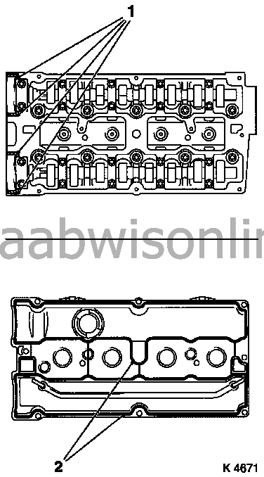
|
|
| 68. |
Fit the DIS ignition module
Unscrew KM-6009 5x Tighten bolt - Tightening torque 8 Nm |
|
| 69. |
Fit the engine management system cable set
13x Fasten cable set connector - Air conditioning pressure sensor, compressor, coolant temperature sensor, fuel evaporation valve, throttle valve module, solenoid valve switch throttle, engine control module, combination connector, fuel regulator lambda sensor, DIS ignition module Fit the nozzle cable duct - Tighten the bolt - Tightening torque 8 Nm Fit the engine vent hose - Fasten the clamp Fit the ground cable. |
|
| 70. |
Fit the fuel line
Tighten the nut - Tightening torque 15 Nm |
|
| 71. |
Fasten the generator
Tighten the bolt - Tightening torque 20 Nm |
|
| 72. |
Fasten the fuel evaporation hose
|
|
| 73. |
Fit the intake side tooth belt guide roller
Tighten the bolt - Tightening torque 25 Nm |
|
| 74. |
Put the crankshaft to ignition TDC for cylinder 1
Put the crankshaft on the mark - Turn the crankshaft at a steady rate Instruction: The marks on the tooth belt sprocket and tooth belt cover must correspond. |
|
| 75. |
Put on the tooth belt Instruction: The pulling side must be taut (I)
|
|
| 76. |
Tension the tooth belt
Tension the tooth belt tensioning pulley - Turn the setting eccenter in the direction of the arrow (anticlockwise) until the pointer on the tooth belt tension roller is just short of the right-hand end position Fasten the bolt for the tooth belt tensioning pulley (1) 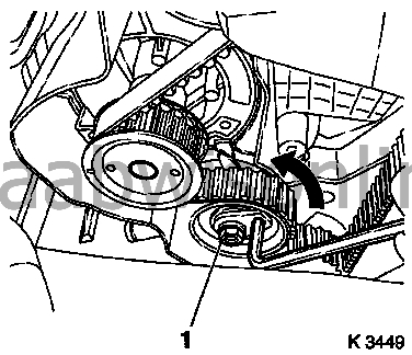
|
|
| 77. |
Remove KM-852 (
83 96 319 Holder tool, fixing of camshaft sprocket Z18XE
)
|
|
| 78. |
Valve timing, check
Turn the crankshaft (720°) - on the bolt for the crankshaft multi-belt pulley Instruction: in the direction of rotation of the engine Put the crankshaft on the mark Instruction: The markings on the tooth belt pulley and rear tooth belt cover must correspond Put in KM-852 Instruction: The markings must be in front of each other and correspond with the top edge of the cylinder head. |
|
| 79. |
Remove KM-852
|
|
| 80. |
Tooth belt tension, setting
Undo the tooth belt tensioning pulley - Undo the bolt Turn the setting eccenter in the direction of the arrow (clockwise) until the pointer (1) on the tooth belt tensioning pulley corresponds with the groove (2) - Adjust a used tooth belt to the USED mark - Adjust a new tooth belt to the NEW mark Tighten the bolt for the tooth belt tensioning pulley - Tightening torque 20 Nm 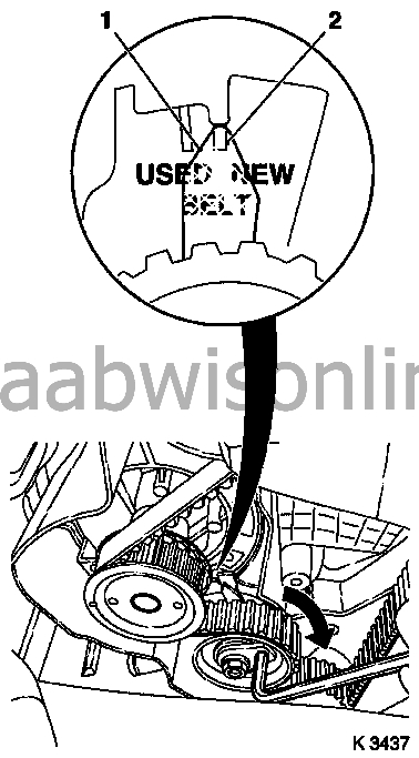
|
|
| 81. |
Tooth belt tension, check
Turn the crankshaft (720°) Instruction: The pointer on the tooth belt tensioning pulley and the groove must agree- Adjust a used tooth belt to the USED mark - Adjust a new tooth belt to the NEW mark |
|
| 82. |
Clean the threads.
2x Clean threads - For camshaft sensor |
|
| 83. |
Fit the camshaft sensor.
Instruction: Fit the bolts with locking compound (red) 2x Tighten bolt - Tightening torque 8 Nm Fasten the cable set connector - Fasten the camshaft sensor cable set connector Tighten the stud - Tightening torque 15 Nm Tighten the nut - Tightening torque 15 Nm - From the fuel line holder |
|
| 84. |
Fit the bottom of the tooth belt cover
Fasten the rear tooth belt cover Tighten the bolt - Tightening torque 4 Nm |
|
| 85. |
Fit the top of the tooth belt cover
Fasten the rear tooth belt cover 3x Tighten bolt - Tightening torque 4 Nm |
|
| 86. |
Raise the car
|
|
| 87. |
Fasten the generator
Tighten the nut - Tightening torque 35 Nm |
|
| 88. |
Fit the engine management system cable set
3x Fasten the cable set connector - Oil pressure switch, crankshaft sensor, dynamic oil level sensor Fasten the cable set |
|
| 89. |
Fit the intake manifold support
on the intake manifold - Tighten the bolt - Tightening torque 20 Nm on the engine block - Tighten the bolt - Tightening torque 35 Nm |
|
| 90. |
Put in place the exhaust system
Instruction: 2 technicians are needed |
|
| 91. |
Fit the exhaust system
Instruction: Change the seal 3x Change nut 3x Tighten nut - Tightening torque 25 Nm |
|
| 92. |
Fit the multi-belt tensioning device
Tighten the bolt - Tightening torque 35 Nm Tension the multi-belt tensioning device - Use KM-913-A Put in KM-6130 |
|
| 93. |
Fit the crankshaft multi-belt pulley
Use KM-911 Change the bolt Tighten the bolt - Tightening torque 95 Nm + 30° + 15° Remove KM-911 Put in the screw plug |
|
| 94. |
Fit the multi-belt
Instruction: Observe the rotation direction and fitting position Undo the multi-belt tensioning device - Use KM-913-A Remove KM-6130 
|
|
| 95. |
Close the coolant drain screw
|
|
| 96. |
Drain the engine oil
Place a receptacle underneath Unscrew the oil drain screw |
|
| 97. |
Remove the oil filter
Place a receptacle underneath Use KM-726-A 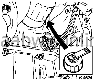
|
|
| 98. |
Fit the oil filter Instruction: Moisten the sealing ring with oil
Tighten the oil filter - Use KM-726-A - Tightening torque 15 Nm |
|
| 99. |
Screw tight the oil drain screw
Change the sealing ring - Tightening torque 14 Nm |
|
| 100. |
Fit the wing liner
|
|
| 101. |
Fit the front right wheel
.
|
|
| 102. |
Lower the car
|
|
| 103. |
Fit the air filter housing
Fit the intake hose Fit the engine vent hose Connect cable set connector Fasten the cable set |
|
| 104. |
Fit the engine cover
Unscrew the lid on the oil filler connection 2x Tighten bolt - Tightening torque 8 Nm Screw on the lid on the oil filler connection |
|
| 105. |
Connect the battery.
|
|
| 106. |
Fill with engine oil and coolant
Observe the prescribed engine oil and coolant volumes Start the engine and allow it to run until the oil pressure control display goes out. Check the engine oil level and top up as necessary. Instruction: Fill and bleed the cooling system - see procedure Bleeding the cooling system . |
|
| 107. |
Reset the service interval with Tech2 as described in
Engine oil change
.
|
|
| 108. |
Complete the service label.
|
|
| 109. |
Close the bonnet
|
|
| 110. |
Program erased memories
|
|
