PRE-RELEASE
Engine with gearbox, removing and fitting
| Engine with gearbox, removing and fitting |
| To remove |
| 1. |
Secure the steering wheel with the column lock with the wheels pointing straight ahead. Fabric tape can also be used.
|
|
| 2. |
Disconnect the battery.
Remove the ground cable. |
|
| 3. |
Hang two
83 95 212 Strap
over the radiator member.

|
|
| 4. |
Raise the car
|
|
| 5. |
Remove the front wheels.
|
|
| 6. |
Remove the spoiler shield.
Detach the front part of the wing liner and bend away. Suspend the radiator assembly with the straps. |
|
| 7. |
Drain the coolant
Place a receptacle underneath Open the drain screw (arrow) Lower the car. 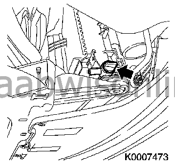
|
|
| 8. |
Remove the upper engine cover.
Unscrew the lid on the oil filler connection 2x Unscrew Screw on the lid on the oil filler connection |
|
| 9. |
Remove the battery.
Disconnect the positive cable (1) Remove the battery holder (2) - Undo the screw (3) 
|
|
| 10. |
Remove the battery holder
Undo the ground distributor - Undo the screw Undo the positive distributor - Undo the screw 3x Unscrew Detach the coolant hose |
|
| 11. |
Dismantle the engine management system cable set
Undo the engine bay fuse holder - 2x unscrew Undo the cable set contacts - 2x unscrew Remove the ground cable. Undo the cable set 
|
|
| 12. |
Detach the coolant hoses from the engine
|
|
| 13. |
Remove the air cleaner casing (1)
Pull off the cable set connector (2) - mass air flow sensor Undo the cable set (arrows) Detach the engine ventilation hose (3) Detach the intake hose (4) Pull off the pressure switch cable set connector 
|
|
| 14. |
Remove the multi-belt.

|
|
| 15. |
Remove the electric connection. Undo the A/C compressor and suspend it with
83 95 212 Strap

|
|
| 16. |
Lower the fuel pressure
Use 83 94 744 Adapter, fuel pressure gauge Unscrew the test connector protective collar on the fuel rail |
||||||||||||||||||||||||
 Warning
| 17. |
Remove the fuel line
Undo the fuel line holder - Unscrew the nut Close the fuel line - Use KM-807 
|
|
| 18. |
Detach the fuel evaporation hose
Use 83 95 261 Fuel line tool . |
|
| 19. |
Remove the coolant equalising container
3x Remove the coolant hose Pull off the cable set connector |
|
| 20. |
2x Remove the water hose (1)
|
|
| 21. |
Detach the brake servo vacuum line (2)
From intake manifold 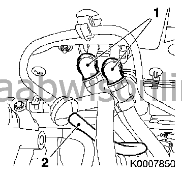
|
|
| 22. |
Detach the selector mechanism wires

Press loose the ball joints from the control levers Take out the supports Detach the electrical connection on the reversing light switch Clamp the clutch hose using 30 07 739 Hose pinch-off pliers Remove the union from the slave cylinder 
|
|
| 23. |
Raise the car
|
|
| 24. |
Close the coolant drain screw
|
|
| 25. |
2x Undo the drive shaft
2x Unscrew nut (3) 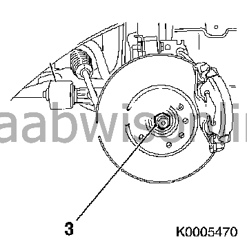
|
|
| 26. |
2x Remove the track rod ball joint
from steering swivel member 2x Unscrew nut 2x Remove track rod ball joint (1) use 87 91 287 Puller, 150 mm 
|
|
| 27. |
2x Remove pitman arm
from spring strut support pipe 2x Unscrew nut (3) Instruction: Hold with an open spanner. |
|
| 28. |
2x Remove track rod (5)
from steering swivel member 2x Unscrew nut (4) - 2x Remove bolt |
|
| 29. |
2x Press out the drive shaft
Use 89 96 951 Puller, drive shaft or KM-6282 (1) Instruction: Fit KM-6282 onto the front wheel hub with 3 wheel bolts 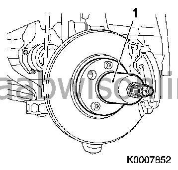
|
|
| 30. |
Raise the car
|
|
| 31. |
Detach the cable set connector for the catalytic converter control lambda sensor
Important: When removing the middle silencer, a catalytic converter, an exhaust manifold or an exhaust manifold with catalytic converter, the components of the exhaust system remaining on the car must be supported to stop them hanging. The exhaust system component with the flexible pipe can be fastened to the underbody using a suitable object, e.g. steel wire. If the flexible pipe bends 5 - 10 degrees from its intended mounting position there may be damage caused and complete failure of the flexible pipe. |
|
| 32. |
Remove the exhaust system
Remove the front exhaust pipe - 3x Unscrew nut 
|
|
| 33. |
Remove the exhaust system
Instruction: 2. A technician is needed Undo the exhaust system - 5x Thrust ring |
|
| 34. |
Remove the steering intermediate spindle
Important: Do not change the position of the steering wheel. Leave the steering column lock engaged or fix the steering wheel to the dashboard with adhesive tape. Undo the clamp screw (1) 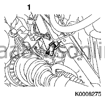
|
|
| 35. |
Remove the wing liner front nuts on both sides
|
|
| 36. |
Fit KM-6313
(83 96 145 Centring fixture, subframe - engine)
with
83 96 368 Additional kit for centring fixture
(1)
Place KM-6313 ( 83 96 145 Centring fixture, subframe - engine ) on the left of the front axle member (arrows, picture I) Instruction: The guide bolt must be in the hole in the subframe 2x Place the right holder on the subframe (arrows, picture II) Instruction: The guide bolt must be in the hole in the subframe (arrow, picture III) 2x Tighten bolt 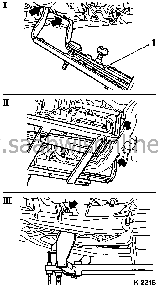
|
|
| 37. |
Fit support
Adjust support mounting Screw on the nut |
|
| 38. |
3x Adjust the support
Gearbox side Instruction: Turn the spindle until the brackets (1) are firmly against the guide pins Engine control side Instruction: Place the support pin firmly into the hole in the engine block (arrow), tighten the nut, bolts and support 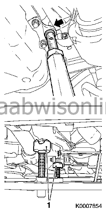
|
|
| 39. |
Lower the car
|
|
| 40. |
Undo the right engine pad adapter
3x Unscrew (1) 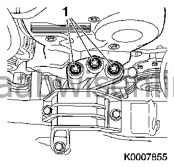
|
|
| 41. |
Undo the left engine holder adapter
3x Unscrew (1) 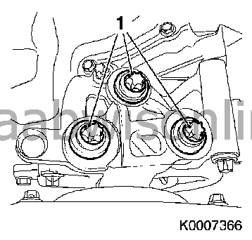
|
|
| 42. |
Raise the car
|
|
| 43. |
Position a
83 95 311 Trolley lift
with
83 94 801 Parent fixture
underneath.
|
|
| 44. |
Fit KM-6312 or
83 96 137 Centring tool, subframe - body
Place KM-6312 (2) 83 96 137 Centring tool, subframe - body - Onto KM-904 (1) or 83 95 188 Basic fixture Instruction: Lower the body location pins (3) Put in place KM-6312 Instruction: Firmly under the front axle member, observing the centring points in the front axle member (arrow) 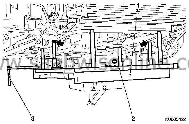
|
|
| 45. |
Undo the subframe
Important: Do not use an impulse or impact nut runner to undo the subframe 7x Undo the bolt (arrows) Important: Lower the subframe with the engine and gearbox carefully out of the engine bay. Do not damage any components |
|
| 46. |
Lower the power unit
Instruction: 2 Technicians are needed |
|
| 47. |
Run out the drive unit
|
|
| 48. |
Check the threads
8x Check the clamp nut |
|
| 49. |
Clean the threads
From the clamping piece To fit |
|
| 50. |
Run in the drive unit
Instruction: Fix the body locating pins in the upper position |
|
| 51. |
Lift up the drive unit
Instruction: 2. Technicians are needed Important: Run in the front axle member with engine and gearbox carefully into the engine bay. Do not damage any components Run the body locating pins into the body locating holes |
|
| 52. |
Fit the subframe. Tightening torque: 75 Nm + 135° (55 lbf ft +135°)


|
|
| 53. |
Run out the trolley lift
|
|
| 54. |
Remove the straps
|
|
| 55. |
Lower the car
|
|
| 56. |
Fit the left engine holder adapter
3x Tighten bolt - Tightening torque 55 Nm |
|
| 57. |
Fit the right engine pad adapter
3x Tighten bolt - Tightening torque 55 Nm |
|
| 58. |
Raise the car
|
|
| 59. |
Remove the support
Engine control side |
|
| 60. |
Remove KM-6313 or
83 96 145 Centring fixture, subframe - engine
|
|
| 61. |
Fit the steering intermediate spindle
Instruction: Before fitting the clamp bolt, check that the groove in the steering gear spindle is aligned with the intermediate spindle hole. Clean the threads and apply 74 96 268 Thread locking adhesive to the threads. Tightening torque 30 Nm (22 lbf ft) |
|
| 62. |
Put in place the exhaust system
Instruction: 2 Technicians are needed |
|
| 63. |
Fit the exhaust system
Instruction: Change the seal 3x Change nut 3x Tighten nut - Tightening torque 20 Nm |
|
| 64. |
Fasten the cable set connector for the catalytic converter control lambda sensor
|
|
| 65. |
Lower the car
|
|
| 66. |
2x Pull in the drive shaft
Instruction: Change nuts 2x Screw on nuts |
|
| 67. |
2x Fit track rod
Instruction: Change nuts and bolts 2x Tighten nut - Tightening torque 50 Nm
|
|
| 68. |
2x Fit the pitman arm
Instruction: Change nuts 2x Tighten the nut Instruction: Hold with an open spanner - Tightening torque 65 Nm |
|
| 69. |
2x Fit track rod ball joint
Instruction: Change nuts 2x Tighten nut - Tightening torque 35 Nm |
|
| 70. |
Lower the car
|
|
| 71. |
2x Fasten drive shaft
2x Tighten the nut Instruction: Torque tighten nuts to 150 Nm, undo 45° and tighten to 250 Nm |
|
| 72. |
Attach the selector mechanism wires
Press the ball joint onto the control lever Fasten the selector mechanism wire in the support |
|
| 73. |
Fit the quick coupling for the clutch slave cylinder. Remove the hose pinch-off pliers. Make sure the connection is fixed in the right position.
Fit the reversing light switch connection Bleed the clutch. See Bleeding the clutch hydraulic system in situ |
|
| 74. |
Fit the brake servo vacuum line
Instruction: The connection should make an audible click |
|
| 75. |
2x Fit hot water hose
|
|
| 76. |
Fit the coolant equalising container
3x Fit the coolant hose Connect cable set connector |
|
| 77. |
Fit EVAP canister purge valve hose
|
|
| 78. |
Fit the fuel line
Fasten the fuel line holder - Tighten nut |
|
| 79. |
Fit the A/C compressor
- Tightening torque 20 Nm Plug in the connector |
|
| 80. |
Fit the multi-belt.
|
|
| 81. |
Fit the air filter housing
Fit the intake hose Fit the engine vent hose Connect cable set connector Fasten the cable set Fasten the pressure switch cable set connector |
|
| 82. |
Fit the coolant hoses to the engine
|
|
| 83. |
Fit the engine management system cable set
Fit cable set connector II Fit cable set connector I 2x Tighten bolt - Tightening torque 2.5 Nm Fit the ground cable. Fasten the engine bay fuse holder - 2x Tighten the bolt Fasten the cable set |
|
| 84. |
Fit the battery holder
3x Tighten bolt Fit the ground distributor - Tighten the bolt Fit the positive distributor - Tighten the bolt Fasten the cable set |
|
| 85. |
Fit the battery.
Fit the battery holder - Tighten the bolt Fit the positive cables Fit the guard |
|
| 86. |
Raise the car
|
|
| 87. |
Fit the spoiler shield
|
|
| 88. |
Lower the car
|
|
| 89. |
2x Fit the front wheel
|
|
| 90. |
Fit the upper engine cover.
Unscrew the lid on the oil filler connection 2x Tighten bolt - Tightening torque 8 Nm Screw on the lid on the oil filler connection |
|
| 91. |
Connect the battery.
|
|
| 92. |
Fill with coolant
Instruction: Fill and bleed the cooling system - See Cooling system, filling and bleeding Observe the prescribed amount of coolant |
|
| 93. |
Program erased memories
|
|
| 94. |
Test drive and check steering wheel position. Adjust as necessary.
|
|
