Cylinder head in car, Z19DTH
|
|
Cylinder head in car, Z19DTH
|
 Warning
|
|
The work involved in removing the fuel pipe requires working with the vehicle's fuel system. The following points should therefore be heeded in conjunction with these measures:
|
|
• Have a class BE fire extinguisher on hand! Be aware of the risk of sparks, i.e. in connection with electric circuits, short-circuiting, etc.
|
|
• Absolutely No Smoking!
|
|
• Ensure good ventilation! If there is approved ventilation for evacuating fuel fumes then this must be used.
|
|
• Wear protective gloves! Prolonged exposure of the hands to fuel can cause irritation to the skin.
|
|
• Wear protective goggles.
|
|
|
|
|
|
|
Warning
|
|
Diesel under high pressure! So wait for at least one minute after switching off the engine before starting work in the fuel system. Diesel fumes are explosive and can cause severe burn injuries.
|
|
|
|
|
|
|
Important
|
|
Always use wing covers when working in the engine bay.
|
|
|
|
1.
|
Remove the engine cover and battery cover. Detach the negative cable from the battery.
|
Warning
|
|
The cooling system is under pressure. Hot coolant and steam can escape.
|
|
- Open the cap slowly to release the pressure.
|
|
- Carelessness can cause eye and burn injuries
|
|
|
|
|
|
|
|
2.
|
Take the cap off the expansion tank to release any pressure.
|
|
4.
|
Remove the front right wheel.
|
|
5.
|
Remove the right wing liner.
|
|
6.
|
Remove the lower engine cover.
|
|
7.
|
Undo the right-hand part of the front lower cover and bend down.
|
|
8.
|
Place a receptacle under the radiator, connect a hose to the radiator and drain the coolant. Close the cock and fit the cover.
|
|
9.
|
Undo the turbo return oil pipe from the engine block.
|
|
10.
|
Loosen the bottom bracket on the front catalytic converter slightly.
|
|
12.
|
Undo the front exhaust pipe from the catalytic converter and gearbox. Lower the pipe on the centring tool.
|
|
13.
|
Remove the lower nuts and bolt from the catalytic converter heat shield.
|
|
15.
|
Remove the crankshaft pulley and idler pulley.
|
|
17.
|
Remove the turbocharger delivery hose from the pipe and throttle body.
|
|
18.
|
Remove the upper coolant hose from the thermostat housing.
|
|
19.
|
Remove the air exhaust hose from the radiator.
|
|
20.
|
Remove the air exhaust hose from the cylinder head.
|
|
21.
|
Remove the electrical connection from the fan cowling.
|
|
22.
|
Remove the radiator pipe to the reservoir from the engine, two mountings, and the hose from the manifold.
|
|
23.
|
Remove the coolant level sensor connector and lift away the reservoir.
|
|
24.
|
Remove the mass air flow sensor connector.
|
|
25.
|
Remove the AC pressure sensor connector.
|
|
26.
|
Remove the air cleaner cover and the air cleaner. Detach the inlet hose and remove the air cleaner casing.
|
|
27.
|
Remove the turbocharger delivery pipe and hose from the turbocharger outlet. Plug the connections.
|
|
28.
|
Remove the screw holding the dipstick tube.
|
|
29.
|
Remove the crankcase ventilation hose from the pipe.
|
|
30.
|
Remove the turbocharger intake pipe. Plug the connections.
|
|
31.
|
Remove the right-hand engine mounting.
|
|
32.
|
Remove the upper timing cover.
|
|
33.
|
Remove the lower coolant hose from the coolant pipe.
|
|
34.
|
Remove the coolant hoses from the coolant pipe.
|
|
35.
|
Remove the vacuum hose.
|
|
36.
|
Undo the bolt holding the turbocharger intake pipe upper retaining bracket slightly.
|
|
37.
|
Remove the coolant pipe from the cylinder head.
|
|
38.
|
Remove the EGR pipe between the exhaust manifold and the heat exchanger.
|
|
39.
|
Remove the heat shield.
|
|
40.
|
Remove the exhaust manifold nuts and fold forward to free the studs.
|
|
41.
|
Remove the lower timing cover.
|
|
42.
|
Undo the wiring harness from the crankcase ventilation pipe. Remove the bolts holding the pipe and bend it aside.
|
|
44.
|
Turn round the engine until the tool engages and locks the exhaust camshaft.
|
|
46.
|
Remove the tension roller and the timing belt.
|
|
47.
|
Undo the EGR pipe from the EGR valve.
|
|
48.
|
Remove the EGR valve connector (606).
|
|
49.
|
Remove the engine cover bracket from the EGR valve.
|
|
50.
|
Remove the EGR valve.
|
|
51.
|
Remove the brake servo hose from the vacuum pump and bend aside.
|
|
52.
|
Undo the vacuum hoses from the vacuum reservoir and pump. Remove the vacuum pipe from the camshaft housing.
|
|
53.
|
Undo the crankcase ventilation hoses from the cylinder head.
|
|
54.
|
Remove the coolant hoses from the thermostat housing and EGR cooler. Place a receptacle under the engine to collect the coolant.
|
|
55.
|
Undo the fixing and press down the wiring harness slightly.
|
|
56.
|
Remove the nuts holding the coolant pipe to the starter motor bracket. Bend away the pipe slightly to give room for the vacuum reservoir.
|
|
57.
|
Remove the vacuum container.
|
|
58.
|
Remove the nuts and bolts holding the oil trap bracket and bend it aside.
|
|
59.
|
Remove the combustion circulation actuator, prise the control arm loose from the ball joint.
|
|
60.
|
Remove the cable duct retaining screws.
|
|
61.
|
Remove the following connectors:
|
|
|
61.a.
|
A/C compressor connector.
|
|
|
61.b.
|
Front temperature sensor (602).
|
|
|
61.c.
|
Camshaft position sensor (555).
|
|
|
61.e.
|
Fuel pressure sensor (653).
|
|
|
61.f.
|
Fuel pressure control valve (652a).
|
|
|
61.g.
|
Throttle body actuator unit (604).
|
|
|
61.h.
|
Intake air sensor (688).
|
|
|
61.i.
|
Glow plug connector.
|
|
|
61.j.
|
Coolant temperature sensor (202).
|
|
62.
|
Fold away the engine wiring harness.
|
|
63.
|
Remove the fuel return hoses from the fuel return collector.
|
|
64.
|
Remove the fuel delivery pipe between the pump and the fuel rail.
|
Important
|
|
If the injectors are to be refitted, mark the injectors so that they can be refitted to the same cylinder.
|
|
|
|
|
66.
|
Remove the fuel rail and hose.
|
|
67.
|
Remove the bolt between the fuel pump bracket and cylinder head, screw out the spacer bolt a few turns.
|
|
68.
|
Undo and remove the camshaft housing and guide sleeves. Loosen bolts alternately as illustrated.
|
|
69.
|
Remove the cylinder head by undoing the bolts in the illustrated order.
|
|
70.
|
Carefully lift off the cylinder head.
|
Important
|
|
Do not confuse the engine block guide sleeves with the camshaft guide sleeves.
|
|
|
|
|
71.
|
Remove the engine block guide sleeves.
|
|
1.
|
Clean the bolt holes in the cylinder block.
|
|
2.
|
Clean away any gasket remains from the cylinder head and cylinder block sealing surfaces.
|
|
3.
|
Check the flatness of the cylinder head and cylinder block with a steel rule and inspect for damage to the sealing surfaces.
|
Important
|
|
Do not confuse the engine block guide sleeves with the camshaft guide sleeves.
|
|
|
|
|
4.
|
Place the guide sleeves on the engine block.
|
|
5.
|
Fit a new gasket with the same thickness as the old one.
|
|
6.
|
Position the cylinder head on the cylinder block.
|
|
7.
|
Tighten the cylinder head bolts in the illustrated order.
Tightening torque
Stage I 65 Nm (48 lbf ft)
Stage II +90°
Stage III +90°
Stage IV +90°
|
|
8.
|
Clean the cylinder head and camshaft housing sealing surfaces from any gasket residue.
|
|
9.
|
Fit the guide sleeves and fit a new gasket onto the cylinder head.
|
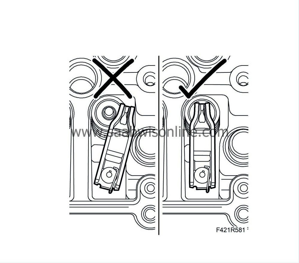
Note
|
|
Check that all the rocker arms are positioned correctly on the valve stems.
|
|
|
10.
|
Fit the camshaft housing, tighten the bolts alternately. Make sure the guide sleeves are positioned correctly in the camshaft housing.
Tightening torque 25 Nm (18 lbf ft).
|
|
11.
|
Screw in the spacer sleeve against the cylinder head and fit the bolt.
|
|
12.
|
Fit the fuel rail and hose.
|
|
14.
|
Fit the fuel delivery pipe between the pump and the fuel rail.
Tightening torque 25 Nm (18 lbf ft).
|
|
15.
|
Fit the fuel return hose to the fuel return collector.
|
|
16.
|
Fold the engine wiring harness back in place and fit the following connectors:
|
|
|
16.a.
|
A/C compressor connector
|
|
|
16.b.
|
Front temperature sensor (602)
|
|
|
16.c.
|
Camshaft position sensor (555)
|
|
|
16.e.
|
Fuel pressure sensor (653)
|
|
|
16.f.
|
Fuel pressure control valve (652a)
|
|
|
16.g.
|
Throttle body actuator unit (604)
|
|
|
16.h.
|
Intake air sensor (688)
|
|
|
16.i.
|
Glow plug connector
|
|
|
16.j.
|
Coolant temperature sensor (202)
|
|
17.
|
Fit the cable duct retaining screws and fix the wiring harness.
|
|
18.
|
Fit the swirl throttle actuator. Press on the control arm to the ball joint. Use a suitable pair of pliers.
|
|
19.
|
Bend the oil trap bracket back in place and fit the nuts and bolts.
|
|
20.
|
Fit the vacuum container.
|
|
21.
|
Fit the nuts holding the coolant pipe to the starter motor bracket.
|
|
22.
|
Fix the wiring harness to the bracket.
|
|
23.
|
Fit the coolant hoses on the thermostat housing and the EGR cooler.
|
|
24.
|
Fit the crankcase ventilation hoses onto the cylinder head.
|
|
25.
|
Fit the vacuum pipe on the camshaft housing and connect the hoses to the vacuum reservoir and pump.
|
|
26.
|
Fit the brake servo hose to the vacuum pump. Secure the hose.
|
|
27.
|
Fit the EGR valve with new gasket.
|
|
28.
|
Fit the engine cover bracket to the EGR valve.
|
|
29.
|
Fit the EGR valve connector (606).
|
|
30.
|
Fit the EGR pipe with a new gasket.
|
|
31.
|
Fit the timing belt so that the marks on the belt agree with the marks on the crankshaft, exhaust camshaft and fuel pump sprockets.
|
|
34.
|
Fit the belt tensioner without tightening the bolt.
|
|
35.
|
Adjust so that the belt tensioner arrow is right in front of the mark by pressing the setting lever in the direction of the arrow. Tighten the belt tensioner using a large screwdriver and an M8 bolt for support.
Tightening torque 25 Nm (18 lbf ft).
|
|
36.
|
Remove the adjustment tool and turn the crankshaft 2 turns.
|
|
38.
|
Remove the tool and fit the plug on the camshaft cover and the bolt to the oil pump.
|
|
39.
|
Fit the crankcase ventilation pipe and secure the wiring harness to the pipe.
|
|
40.
|
Fit the lower timing cover.
|
|
41.
|
Put on a new gasket and lift up the exhaust manifold. Fit the nuts.
Tightening torque 20 Nm (15 lbf ft).
|
|
43.
|
Fit the EGR pipe between the exhaust manifold and the heat exchanger with new gaskets.
|
|
44.
|
Tighten the bolt on the turbocharger intake pipe bracket.
|
|
45.
|
Fit the coolant pipe on the cylinder head with a new gasket.
|
|
46.
|
Connect the vacuum hose.
|
|
47.
|
Fit the coolant hoses to the coolant pipe.
|
|
48.
|
Fit the lower coolant hose on the coolant pipe.
|
|
49.
|
Fit the upper timing cover.
|
|
50.
|
Fit the right-hand engine mounting.
Tightening torque on engine, 50 Nm (137 lbf ft)
Tightening torque to body 40 Nm + 60° (30 lbf ft + 60°).
|
|
51.
|
Fit the turbocharger intake pipe.
|
|
52.
|
Fit the crankcase ventilation hose to the pipe.
|
|
53.
|
Fit the screw holding the dipstick tube.
|
Important
|
|
To reduce the risk of hoses mounted on the delivery side of the turbocharger coming loose due to low friction at high air pressure, the hoses and connecting pieces must be cleaned thoroughly before fitting. Use a rag dampened with 93 160 907 Motip Dupli cleaning agent to wipe clean inside the ends of the hoses. Clean the connecting pieces as well. If hose clips are rusty or damaged, they must be replaced so the correct clamping force is maintained.
|
|
|
|
|
54.
|
Remove the plugs and fit the turbocharger delivery pipe and hose to the turbocharger outlet.
|
|
55.
|
Fit the air filter housing. Fit the air filter and air filter housing cover as well as the intake hose.
|
|
56.
|
Plug in the mass air flow sensor connector.
|
|
57.
|
Fit the AC pressure sensor connector.
|
|
58.
|
Fit the coolant tank onto the bulkhead and plug in the level sensor connector.
|
|
59.
|
Fit the radiator pipe to the reservoir from the engine, two mountings, and the hose from the manifold.
|
|
60.
|
Fit the electrical connection on the fan cowling.
|
|
61.
|
Fit the air exhaust hose onto the cylinder head.
|
|
62.
|
Fit the air exhaust hose onto the radiator.
|
|
63.
|
Fit the upper coolant hose to the thermostat housing.
|
Important
|
|
To reduce the risk of hoses mounted on the delivery side of the turbocharger coming loose due to low friction at high air pressure, the hoses and connecting pieces must be cleaned thoroughly before fitting. Use a rag dampened with 93 160 907 Motip Dupli cleaning agent to wipe clean inside the ends of the hoses. Clean the connecting pieces as well. If hose clips are rusty or damaged, they must be replaced so the correct clamping force is maintained.
|
|
|
|
|
64.
|
Fit the turbocharger delivery pipe to the turbocharger delivery hose and the throttle body.
|
|
66.
|
Fit the crankshaft pulley.
|
Note
|
|
Make sure the guide pin is in its recess.
|
Tightening torque 25 Nm (18 lbf ft).
|
|
69.
|
Fit the lower nuts and bolt to the front catalytic converter heat shield.
|
|
70.
|
Lift up and fit the front exhaust pipe to the catalytic converter and the gearbox with a new gasket.
Tightening torque 25 Nm (18 lbf ft).
|
|
71.
|
Remove the engine fixing tool from the subframe. Fit the bolt to the A/C compressor bracket.
|
|
72.
|
Tighten the front catalytic converter lower bracket.
|
|
73.
|
Fit the turbo return oil pipe with a new gasket.
|
|
74.
|
Fit the lower engine cover.
|
|
75.
|
Fit the right-hand wing liner.
|
|
79.
|
Change engine oil and filter.
|
|
80.
|
Connect the negative battery cable and fit the battery cover.
|
|
82.
|
Connect an exhaust hose and start the engine. Check that there are no leaks.
Connect the diagnostic tool and erase any diagnostic trouble codes.
|
|
83.
|
Fit the engine cover.
|

