PRE-RELEASE
Detailed description
| Detailed description |
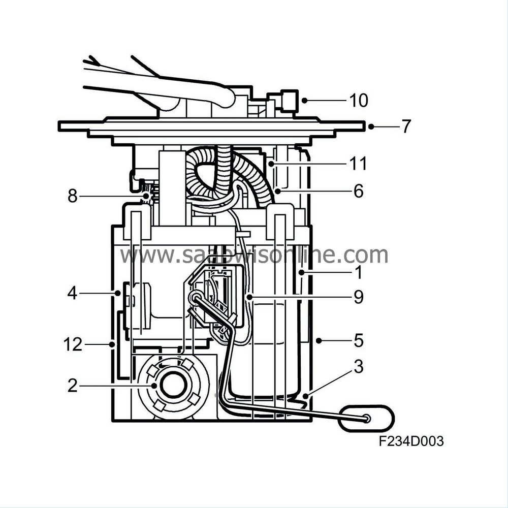
| 1. |
Pump
|
|
| 2. |
Ejector
|
|
| 3. |
Primary filter, suction side
|
|
| 4. |
Filter, delivery side
|
|
| 5. |
Reservoir
|
|
| 6. |
Pump delivery line
|
|
| 7. |
Pump cover
|
|
| 8. |
Spring element
|
|
| 9. |
Level sensor, fuel (46)
|
|
| 10. |
EVAP pressure sensor (585)
|
|
| 11. |
Float valve, upper
|
|
| 12. |
Float valve, lower
|
|
The fuel pump is located inside a plastic reservoir that is clamped between the top and bottom of the fuel tank and located centrally by protrusions in the bottom of the tank and at the top by the pump cover. The pump is mounted in the tank by screwing the pump cover into a screw ring on the outside of the tank. Movement in the tank is taken up by the fuel pump spring element.
An ejector is "driven" by the flow of fuel from the delivery line via a T-piece. The pump is an electric turbine pump. The ejector is used to ensure the that the pump is supplied with fuel. The location of the pump in the reservoir guarantees the fuel supply when cornering and accelerating even when there is only a small amount of fuel left in the tank.
The reservoir is designed so that a sufficient fuel level is guaranteed in the fuel pump.
A non-return valve on the pump delivery side prevents the pressure in the fuel line dropping as soon as the engine is turned off. The non-return valve on the pump return side prevents the fuel returning the wrong way in case the car should roll over.
The fuel level sensor in the tank is mounted on the fuel pump reservoir via a jointed arm.
| Fuel rail |

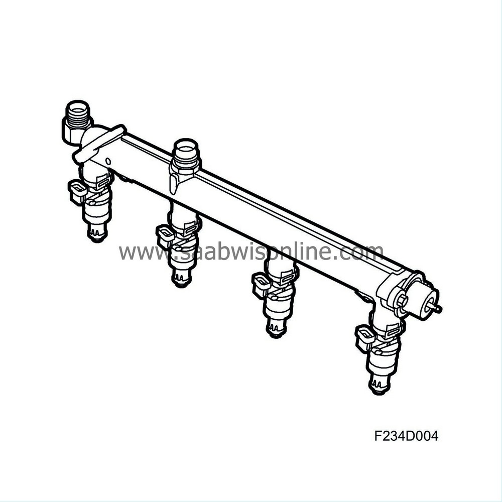
The fuel rail meters equal amounts of fuel to all the injectors. It also acts as a pressure equalizer. In relation to the amount of fuel consumed during each injection, the fuel rail has sufficient capacity to prevent variations in pressure. The design and construction of the fuel rail enables a simple method of fitting the injectors, which are connected directly to it.
Also connected to the fuel rail are the fuel lines and fuel pressure regulator.
| Injectors |

The injectors are connected directly to the fuel rail and are mounted in heat insulated bushings in the cylinder head ahead of the intake valves.
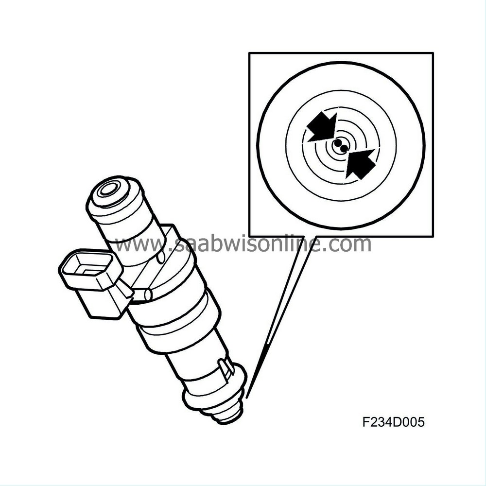
An injector comprises a valve body and nozzle with magneto armature. The valve body contains a magnetic coil and a guide for the nozzle. The injectors are controlled electromagnetically and are opened and closed by electrical impulses from the engine control module.
The injectors are of the two-hole type. This means that they inject one jet of fuel into each intake valve.
The nozzles are secured by clips to the fuel rail. It is essential with regard to emissions and engine performance that the nozzles are positioned and secured correctly.
| Pressure regulator |

The pressure regulator is mounted on the end of the fuel rail.
The regulator maintains a constant differential pressure between the fuel and the intake manifold. In this way, the amount of fuel injected can be determined solely by the electromagnetic injector timing.
The pressure regulator is a diaphragm-controlled overflow valve set for 3.0 bar. It consists of a metal housing divided into two chambers by a press-fitted diaphragm. In one of the chambers there is a spiral spring that presses against the diaphragm while fuel flows through the other chamber.
When the preset pressure is exceeded, a valve controlled by the diaphragm exposes an opening to the return line through which superfluous fuel can flow back to the fuel tank.
The pressure regulator spring chamber is connected to the intake manifold after the throttle body via a hose. This means that the pressure in the fuel system is affected by the absolute pressure in the intake manifold and the drop in pressure across the injectors is constant at each inlet pressure.


