TCM control module, AF40 (502b)
|
|
TCM control module, AF40 (502b)
|
TCM is mounted on top of the gearbox.
Controlling shifting points, system pressure and engagement of lock up.
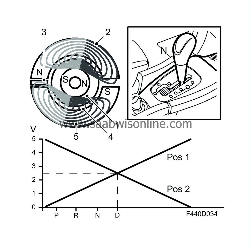
Microprocessor with integrated Hall sensor.
|
3.
|
IC circuit, Hall sensor
|
The TCM is mounted directly on top of the gearbox. The selector lever is integrated in the control module. The TCM is mounted so that the selector lever shaft goes through the control module. The selector lever position is calibrated with Tech2, there is no mechanical adjustment.
An exterior 16-pin connector connects to the car's electrical system. Underneath the control module is another connector (22-pin) that connects directly to the gearbox. TCM makes contact with all the gearbox solenoids and sensors here.
|
Note
|
|
Magnetic fields from e.g. magnets and from high-current cables, such as starter cables and cables to auxiliary equipment, can interfere with the gear position sensor. A rule of thumb is max 1A per mm in distance from the control module. A starter cable carrying a current of 200A must therefore be kept at least 20 cm away from the control module.
|
The TCM has a microprocessor with clock, RAM memory and a programmable ROM. An internal bus connects the processor and memory with the I/O unit. The I/O unit reads values from the A/D converter for analogue inputs, digital inputs and bus, as well as activates the transistors' output stages.
Adaptive values are saved in a non-volatile memory (ROM). When changing gearbox, these values must be zeroed using Tech 2. After changing TCM they will be zeroed automatically after adding the control module using the "Add" menu in Tech 2.
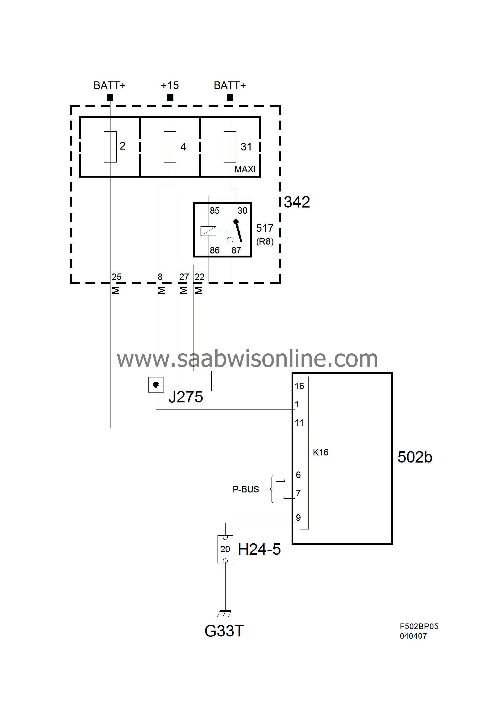
Power supply, ground and bus communication
Contacting the car's electrical system:
|
Pin no.
|
Interface
|
Description
|
|
9
|
Power ground
|
Power supply
|
|
11
|
+30
|
Power supply
|
|
1
|
+15
|
Signal
|
|
7
|
P-bus +
|
Signal to/from other control modules
|
|
6
|
P-bus -
|
Signal to/from other control modules
|
|
8
|
P-bus +
|
Signal to/from other control modules
|
|
14
|
P-bus -
|
Signal to/from other control modules
|
|
3
|
Selector lever
|
Sentronic's gear change request
|
|
16
|
Starter motor relay
|
Power supply in position P/N
|
TCM contact directly to gearbox:
|
Pin no.
|
Interface
|
Description
|
|
1
|
SLT
|
Ground
|
|
2
|
S2
|
Power supply +
|
|
3
|
SLT
|
Power supply +
|
|
4
|
SLU
|
Ground
|
|
5
|
S1
|
Power supply +
|
|
7
|
Temperature sensor
|
Ground
|
|
8
|
Temperature sensor
|
Temperature signal
|
|
9
|
SLU
|
Power supply +
|
|
10
|
SLC1
|
Ground
|
|
11
|
SLC1
|
Power supply +
|
|
12
|
Input shaft speed
|
Rotation speed signal
|
|
13
|
Input shaft speed
|
Ground
|
|
14
|
SLC3
|
Power supply +
|
|
16
|
SLB1
|
Ground
|
|
17
|
SLC2
|
Power supply +
|
|
18
|
SLC2
|
Ground
|
|
19
|
Output shaft speed
|
Rotation speed signal
|
|
20
|
Output shaft speed
|
Ground
|
|
21
|
SLB1
|
Power supply +
|
|
22
|
SLC3
|
Ground
|
|
Important
|
|
When handling the control module, it is important first to create a ground connection between yourself and for example the vehicle engine. Avoid touching the pins of the control module.
|
|
|


