Measurement value, REC (701)
|
|
Measurement value, REC (701)
|
 Directions for the measurement of levels and signals at the REC and the measurement values are given on the following pages.
|
Note
|
|
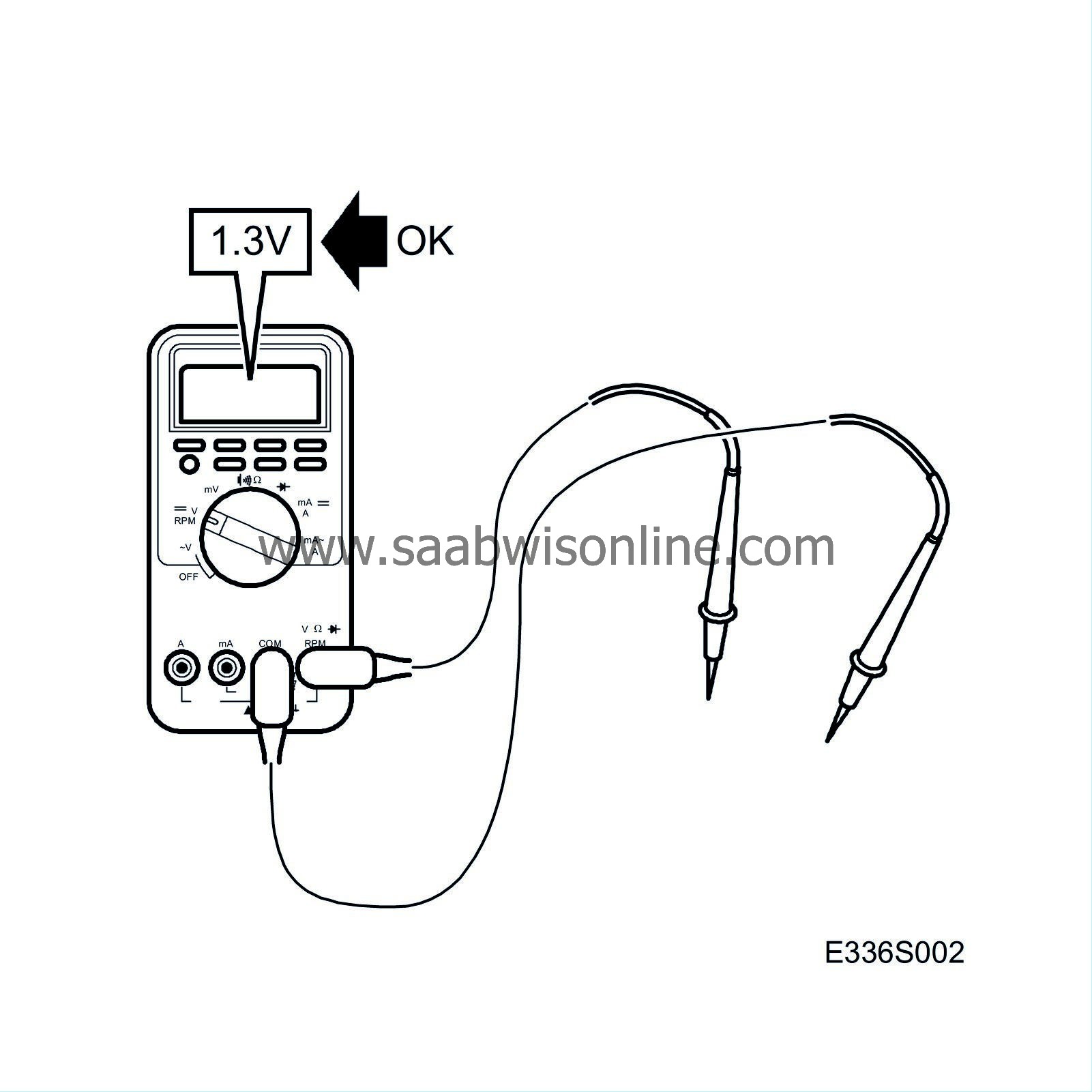
When measuring values at the pins the connector must remain plugged into the electrical centre. The pins can be accessed by lifting up the protective cover on the connector.
|
|
•
|
Pay attention to the measurement requirements, use common sense when judging the measurement result.
|
|
•
|
Check first that there is a voltage supply to the control module and that it is grounded.
|
|
•
|
Then check all sensor inputs and signals from other systems.
|
|
•
|
Lastly check the outputs of the control module. Remember that the output values do not say anything about the functioning of the related actuator.
|
|
•
|
If any measurement value is incorrect, use the wiring diagram to determine which cables, connectors or components should also be checked.
|
|
•
|
The given measurement values are as measured with a calibrated Fluke 88/97.
|
|
•
|
The measurement values %(+) and ms(+) show respectively the pulse ratio and the pulse length. A test instrument with pulse ratio and pulse width measurement must be used. The plus sign (+) denotes a positive trigger pulse, TRIG+.
|
|
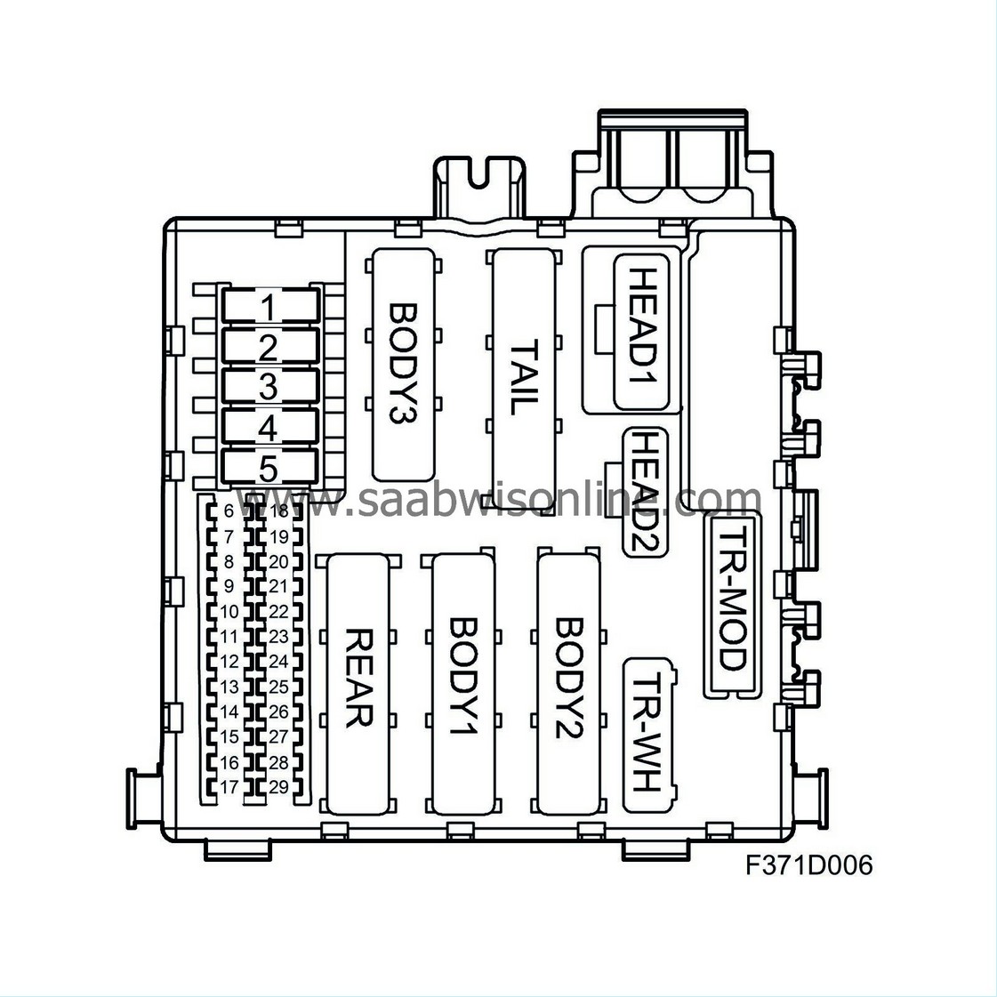
Connector Body 1 to main wiring harness
|
Connector section A (in the diagram = B1-A)
|
Pin
|
Component/Function
|
Component
|
In/Out
|
Measurement requirement.
|
Measure between
|
Measurement value
|
|
1
|
Door control module, RL and RR
|
|
Out
|
Ignition on
|
1 to B-
|
B+
|
|
2
|
DVD unit
|
|
Out
|
Ignition on
|
2 to B-
|
B+
|
|
3
|
Entry point junction to T-A pin 2
|
microswitch, boot lid lock - BCM
|
|
|
|
|
|
4
|
Control module, TPS
|
|
Out
|
Ignition on
|
4 to B-
|
B+
|
|
5
|
Not connected
|
|
|
|
|
|
|
6
|
Not connected
|
|
|
|
|
|
|
7
|
Not connected
|
|
|
|
|
|
|
8
|
Entry point junction to H2 pin 3
|
interior lighting - BCM
|
|
|
|
|
|
9
|
Entry point junction to H2 pin 4
|
interior lighting - BCM
|
|
|
|
|
Connector section B (in the diagram = B1-B)
|
Pin
|
Component/Function
|
Component
|
In/Out
|
Measurement requirement.
|
Measure between
|
Measurement value
|
|
1
|
Not connected
|
|
|
|
|
|
|
2
|
Not connected
|
|
|
|
|
|
|
3
|
Not connected
|
|
|
|
|
|
|
4
|
AMP2
|
|
Out
|
Ignition on
|
4 to B-
|
B+
|
|
5
|
Not connected
|
|
|
|
|
|
|
6
|
Entry point junction to TR-WH pin 4
|
trailer connection - IPRC
|
|
|
|
|
Connector section C (in the diagram = B1-C)
|
Pin
|
Component/Function
|
Component
|
In/Out
|
Measurement requirement.
|
Measure between
|
Measurement value
|
|
1
|
Entry point junction to H2 pin 1
|
interior lighting - BCM
|
|
|
|
|
|
2
|
Electrical heating, RH front seat
|
|
|
Ignition on/off
|
2 to B-
|
B+/0V
|
|
3
|
Electrical heating, LH front seat
|
|
|
Ignition on/off
|
3 to B-
|
B+/0V
|
|
4
|
Not connected
|
|
|
|
|
|
|
5
|
Not connected
|
|
|
|
|
|
|
6
|
Not connected
|
|
|
|
|
|
Connector section D (in the diagram = B1-D)
|
Pin
|
Component/Function
|
Component
|
In/Out
|
Measurement requirement.
|
Measure between
|
Measurement value
|
|
1
|
Not connected
|
|
|
|
|
|
|
2
|
Not connected
|
|
|
|
|
|
|
3
|
Not connected
|
|
|
|
|
|
|
4
|
Entry point junction to T-A pin 6
|
4D.
OnStar
CV:
microswitch, load holder - STC
|
|
|
|
|
|
5
|
Rear CD changer
|
|
|
Ignition on
|
5 to B-
|
B+
|
|
6
|
Not connected
|
|
|
|
|
|
|
7
|
Not connected
|
|
|
|
|
|
|
8
|
Not connected
|
|
|
|
|
|
|
9
|
Not connected
|
|
|
|
|
|
|
Connector Body 2 to main wiring harness
|
Connector section A (in the diagram = B2-A)
|
Pin
|
Component/Function
|
Component
|
In/Out
|
Measurement requirement.
|
Measure between
|
Measurement value
|
|
1
|
Not connected
|
|
|
|
|
|
|
2
|
Not connected
|
|
|
|
|
|
|
3
|
Not connected
|
|
|
|
|
|
|
4
|
I-bus
|
|
In
|
Ignition on
|
4 to B-
|
0.3 - 0.5 V. Test lamp should blink
|
|
5
|
I-bus
|
|
Out
|
Ignition on
|
5 to B-
|
0.3 - 0.5 V. Test lamp should blink
|
|
6
|
Not connected
|
|
|
|
|
|
|
7
|
Not connected
|
|
|
|
|
|
|
8
|
Entry point junction to H2 pin 3
|
interior lighting
|
|
|
|
|
|
9
|
Entry point junction to H1 pin 15
|
anti-theft alarm sensor - BCM
|
|
|
|
|
|
10
|
Not connected
|
|
|
|
|
|
|
11
|
Not connected
|
|
|
|
|
|
|
12
|
Not connected
|
|
|
|
|
|
Connector section B (in the diagram = B2-B)
|
Pin
|
Component/Function
|
Component
|
In/Out
|
Measurement requirement.
|
Measure between
|
Measurement value
|
|
1
|
Entry point junction to H1 pin 11
|
anti-theft alarm sensor - BCM
|
|
|
|
|
|
2
|
Not connected
|
|
|
|
|
|
|
3
|
Entry point junction to T-B pin 3
|
crash signal - ACM
|
|
|
|
|
|
4
|
Not connected
|
|
|
|
|
|
|
5
|
Not connected
|
|
|
|
|
|
|
6
|
Entry point junction to T-B pin 1
|
microswitch, boot lid handle - BCM
|
|
|
|
|
|
7
|
Not connected
|
|
|
|
|
|
|
8
|
Not connected
|
|
|
|
|
|
|
9
|
Not connected
|
|
|
|
|
|
|
10
|
Not connected
|
|
|
|
|
|
|
11
|
Not connected
|
|
|
|
|
|
|
12
|
Not connected
|
|
|
|
|
|
Connector section D (in the diagram = B2-D)
|
Pin
|
Component/Function
|
Component
|
In/Out
|
Measurement requirement.
|
Measure between
|
Measurement value
|
|
1
|
Not connected
|
|
|
|
|
|
|
2
|
Not connected
|
|
|
|
|
|
|
3
|
Not connected
|
|
|
|
|
|
|
4
|
Not connected
|
|
|
|
|
|
|
5
|
Brake light switch
|
|
In
|
Brake lights on
|
5 to B-
|
B+
|
|
6
|
Not connected
|
|
|
|
|
|
|
7
|
Not connected
|
|
|
|
|
|
|
8
|
Not connected
|
|
|
|
|
|
|
9
|
Ignition switch module,
|
|
In
|
Ignition on/off
|
9 to B-
|
12 V/0 V
|
|
10
|
Entry point junction to R-A pin 7
|
locking, fuel filler flap - BCM
|
|
|
|
|
|
11
|
Entry point junction to R-A pin 6
|
unlocking, fuel filler flap - BCM
|
|
|
|
|
|
12
|
Entry point junction to R-A pin 5
|
anti-theft-alarm siren - BCM
|
|
|
|
|
|
Connector Body 3 (in the diagram = B3) to main wiring harness
|
|
Pin
|
Component/Function
|
Component
|
In/Out
|
Measurement requirement.
|
Measure between
|
Measurement value
|
|
1
|
+30-supply
|
|
In
|
|
1 to B-
|
B+
|
|
2
|
+30-supply
|
|
In
|
|
2 to B-
|
B+
|
|
3
|
+30-supply
|
|
In
|
|
3 to B-
|
B+
|
|
4
|
Electrically adjustable seats
|
|
Out
|
Ignition on
|
4 to B-
|
B+
|
|
5
|
Not connected
|
|
|
|
|
|
|
6
|
Door control module, RL
|
|
Out
|
|
6 to B-
|
B+
|
|
7
|
Door control module, RR
|
|
Out
|
|
7 to B-
|
B+
|
|
8
|
Seats
|
|
Out
|
|
8 to B-
|
B+
|
|
9
|
Not connected
|
|
|
|
|
|
|
Connector Head 1 (in the diagram = H1) to roof wiring harness
|
|
Pin
|
Component/Function
|
Component
|
In/Out
|
Measurement requirement.
|
Measure between
|
Measurement value
|
|
1
|
Entry point junction to T-C pin 8
|
microphone cable screen (4D)
|
|
|
|
|
|
2
|
Entry point junction to T-C pin 7
|
microphone+ (4D)
|
|
|
|
|
|
3
|
Entry point junction to T-C pin 5
|
microphone (4D)
|
|
|
|
|
|
4
|
Not connected
|
|
|
|
|
|
|
5
|
Not connected
|
|
|
|
|
|
|
6
|
Sunroof module
|
|
Instrument bus
|
|
|
|
|
7
|
Interior lightning, sunroof module
|
|
In
|
Ignition on
|
7 to B-
|
B+
|
|
8
|
+ 30 power supply, sunroof module
|
|
Out
|
Ignition on
|
8 to B-
|
B+
|
|
9
|
Not connected
|
|
|
|
|
|
|
10
|
+ 30 power supply, anti-theft alarm
|
|
Out
|
Ignition on
|
10 to B-
|
B+
|
|
11
|
Entry point junction to B2-B pin 1
|
anti-theft alarm sensor - BCM
|
|
|
|
|
|
12
|
Sunroof module
|
|
In
|
Ignition on
|
12 to B+
|
B+
|
|
13
|
Not connected
|
|
|
|
|
|
|
14
|
Not connected
|
|
|
|
|
|
|
15
|
Entry point junction to B2-A pin 9
|
anti-theft alarm sensor - BCM (signal)
|
|
|
|
|
|
16
|
Not connected
|
|
|
|
|
|
|
Connector Head 2 (in the diagram = H2) to roof wiring harness
|
|
Pin
|
Component/Function
|
Component
|
In/Out
|
Measurement requirement.
|
Measure between
|
Measurement value
|
|
1
|
Entry point junction to B1-C pin 1
|
interior lighting
|
|
|
|
|
|
2
|
+15 power supply, rain sensor
|
|
Out
|
Ignition on
|
2 to B-
|
B+
|
|
3
|
Entry point junction to B1-A pin 8
|
interior lighting
|
|
|
|
|
|
4
|
Entry point junction to B1-A pin 9
|
interior lighting
|
|
|
|
|
|
5
|
Not connected
|
|
|
|
|
|
|
6
|
Not connected
|
|
|
|
|
|
|
7
|
Not connected
|
|
|
|
|
|
|
8
|
Not connected
|
|
|
|
|
|
|
9
|
Ground, rain sensor
|
|
In
|
|
9 to B+
|
B+
|
|
10
|
+15 power supply ADM
|
|
Out
|
Ignition on
|
10 to B-
|
B+
|
|
11
|
Reversing lights
|
|
|
Ignition on. Reversing lights on.
|
11 to B-
|
B+
|
|
12
|
Not connected
|
|
|
|
|
|
|
13
|
Not connected
|
|
|
|
|
|
|
14
|
Not connected
|
|
|
|
|
|
|
15
|
Elevated brake lights
|
|
Out
|
Ignition on. Elevated brake lights activated with Tech 2
|
15 to B-
|
B+
|
|
16
|
Not connected
|
|
|
|
|
|
|
17
|
Not connected
|
|
|
|
|
|
|
18
|
Not connected
|
|
|
|
|
|
|
19
|
Not connected
|
|
|
|
|
|
|
20
|
Not connected
|
|
|
|
|
|
|
21
|
Not connected
|
|
|
|
|
|
|
22
|
Not connected
|
|
|
|
|
|
|
23
|
Not connected
|
|
|
|
|
|
|
24
|
Rain sensor
|
|
|
|
|
|
|
Rear connector to rear wiring harness
|
Connector section A (in the diagram = R-A)
|
Pin
|
Component/Function
|
Component
|
In/Out
|
Measurement requirement.
|
Measure between
|
Measurement value
|
|
1
|
+30-supply
|
|
Out
|
|
1 to B-
|
B+
|
|
2
|
Luggage compartment lighting (CV)
|
|
|
|
|
|
|
3
|
Signal ground
|
|
Out
|
|
3 to B+
|
B+
|
|
4
|
Instrument bus
|
|
|
|
|
|
|
5
|
Entry point junction to B2-D pin 12
|
Anti-theft-alarm siren
|
|
|
|
|
|
6
|
Entry point junction to B2-D pin 11
|
fuel filler flap solenoid
|
|
|
|
|
|
7
|
Entry point junction to B2-D pin 10
|
fuel filler flap solenoid
|
|
|
|
|
|
8
|
Not connected
|
|
|
|
|
|
|
9
|
+30 siren
|
|
Out
|
|
9 to B-
|
B+
|
Connector section B (in the diagram = R-B)
|
Pin
|
Component/Function
|
Component
|
In/Out
|
Measurement requirement.
|
Measure between
|
Measurement value
|
|
1
|
Power ground
|
|
Out
|
|
1 to B+
|
B+
|
|
2
|
Power ground
|
|
Out
|
|
2 to B+
|
|
|
3
|
Not connected
|
|
|
|
|
|
Connector section D (in the diagram = R-D)
|
Pin
|
Component/Function
|
Component
|
In/Out
|
Measurement requirement.
|
Measure between
|
Measurement value
|
|
1
|
Not connected
|
|
|
|
|
|
|
2
|
Brake/tail light LH
|
|
Out
|
Brake light activated or lighting on
|
2 to B-
|
B+
|
|
3
|
Not connected
|
|
|
|
|
|
|
4
|
Brake/tail light RH
|
|
Out
|
Brake light activated or lighting on
|
4 to B-
|
B+
|
|
5
|
Not connected
|
|
|
|
|
|
|
6
|
Direction indicators RH
|
|
|
Direction indicators RH activated/ lighting on
|
6 to B-
|
test lamp blinks
|
|
7
|
Not connected
|
|
|
|
|
|
|
8
|
Direction indicators LH
|
|
|
Direction indicators RH activated/ lighting on
|
8 to B-
|
test lamp blinks
|
|
9
|
Not connected
|
|
|
|
|
|
|
10
|
Rear parking light RH
|
|
|
Tail light RH activated with Tech 2
|
10 to B-
|
B+
|
|
11
|
Not connected
|
|
|
|
|
|
|
12
|
Rear parking light LH
|
|
|
Tail light LH activated with Tech 2
|
12 to B-
|
B+
|
|
Connector Tail to parcel shelf wiring harness (4D) or rear wiring harness (CV)
|
Connector section A (in the diagram = T-A)
|
Pin
|
Component/Function
|
Component
|
In/Out
|
Measurement requirement.
|
Measure between
|
Measurement value
|
|
1
|
Not connected
|
|
|
|
|
|
|
2
|
Entry point junction to B1-A pin 3
|
boot lid microswitch
|
|
|
|
|
|
3
|
Not connected
|
|
|
|
|
|
|
4
|
Not connected
|
|
|
|
|
|
|
5
|
Not connected
|
|
|
|
|
|
|
6
|
Entry point junction to B1-D pin 4
|
4D:
OnStar CU
CV:
microswitch, load holder
|
|
|
|
|
|
7
|
CU/PU
|
|
Out
|
Ignition on
|
7 to B-
|
B+
|
|
8
|
Not connected
|
|
|
|
|
|
|
9
|
Luggage compartment lighting
|
|
Out
|
Ignition on. Luggage compartment lighting on.
|
9 to B-
|
B+
|
Connector section B (in the diagram = T-B)
|
Pin
|
Component/Function
|
Component
|
In/Out
|
Measurement requirement.
|
Measure between
|
Measurement value
|
|
1
|
Entry point junction to B2-B pin 6
|
centrally operated lock, boot lid
|
|
|
|
|
|
2
|
Not connected
|
|
|
|
|
|
|
3
|
Entry point junction to B2-B pin 6
|
crash signal CU
|
|
|
|
|
|
4
|
Not connected
|
|
|
|
|
|
|
5
|
Not connected
|
|
|
|
|
|
|
6
|
Not connected
|
|
|
|
|
|
|
7
|
Rear seat backrest
|
|
Out
|
Backrest RH locked/lowered
|
7 to B-
|
5 V/3.5 V
|
|
8
|
Rear seat backrest LH
|
|
Out
|
Backrest LH locked/lowered
|
8 to B-
|
5 V/3.5 V
|
|
9
|
Not connected
|
|
|
|
|
|
|
10
|
Number plate lighting
|
|
Out
|
Number plate lighting activated or with Tech 2
|
10 to B-
|
B+
|
|
11
|
Reversing light RH
|
|
Out
|
Reverse gear selected. Ignition on.
|
1 to B-
|
B+
|
|
12
|
Not connected
|
|
|
|
|
|
Connector section C (in the diagram = T-C)
|
Pin
|
Component/Function
|
Component
|
In/Out
|
Measurement requirement.
|
Measure between
|
Measurement value
|
|
1
|
Reversing lights LH
|
|
Out
|
Reverse gear selected. Ignition on.
|
1 to B-
|
B+
|
|
2
|
Rear fog lights
|
|
Out
|
Rear fog light activated or with Tech 2
|
2 to B-
|
B+
|
|
3
|
Boot lid lock (unlocking)
|
|
Out
|
Ignition on. Locking/unlocking
|
3 to B-
|
0/0.2 V
|
|
4
|
Not connected
|
|
|
|
|
|
|
5
|
Entry point junction to H1 pin 3
|
microphone+ to CU (4D)
|
|
|
|
|
|
6
|
Boot lid lock (ground)
|
|
In
|
Ignition on
|
6 to B-
|
0.2 V
|
|
7
|
Entry point junction to H1 pin 2
|
microphone to CU (4D)
|
|
|
|
|
|
8
|
Entry point junction to H1 pin 1
|
microphone cable screen (4D)
|
|
|
|
|
|
9
|
Not connected
|
|
|
|
|
|
Connector section D (in the diagram = T-D)
|
Pin
|
Component/Function
|
Component
|
In/Out
|
Measurement requirement.
|
Measure between
|
Measurement value
|
|
1
|
Not connected
|
|
|
|
|
|
|
2
|
Antenna amplifier
|
|
In
|
Ignition on
|
2 to B+
|
B+
|
|
3
|
Power ground
|
|
In
|
|
3 to B+
|
B+
|


