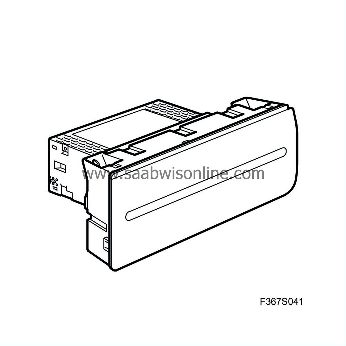
Control panel, infotainment, ICM (736)
|
|
Control panel, infotainment, ICM (736)
|
Infotainment control panel (736)
The control module
|
1.
|
is the control unit for the O-bus, which means that it controls all the unit on the O-bus. ICM is responsible for conveying information between the O-bus and the electric buses (P and I-bus).
|
|
2.
|
Applies only to ICM 1, 2 and 3:
is the control panel for audio, telephone and navigation. ICM shares some logic functions with the radio main unit but is the overall control unit for navigation and communication.
|
|
3.
|
is the control unit for SID and SIDC (SID control panel).
|
The control module governs mainly the following functions:
|
5.
|
Trip computer functions
|
|
6.
|
Warning and indicator messages, language and units.
|
ICM is available in four levels:
|
•
|
ICM 0
is a control module without keypad. ICM 0 is in cars without an audio system.
|
|
•
|
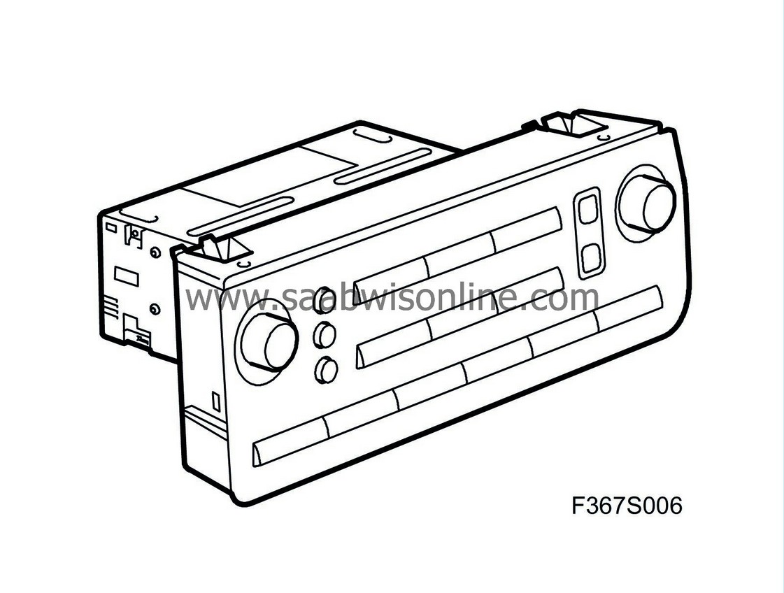
ICM 1
is equipped with only one keypad. The SETTINGS button activates the SID menu, for displaying information relating to the ICM functions.
|
|
•
|
ICM 2
contains a monochrome display and additional buttons for telephone and MAIN /BACK used for menu selection for the ICM display. The SETTINGS button is replaced with a telephone button for ICM 2 and 3.

|
|
•
|
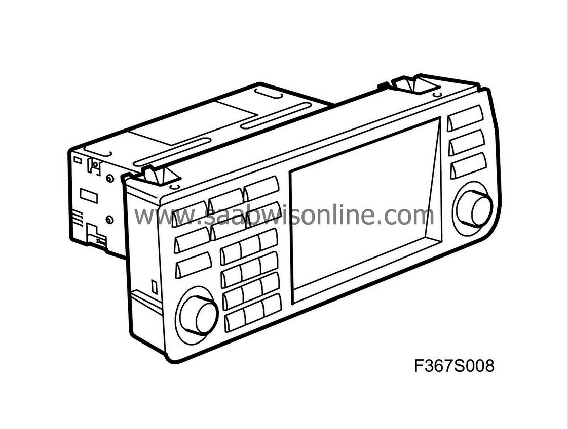
ICM 3
includes a 5.8" colour screen for navigation, etc.
|
The four control module variants (ICM 0-3) all have the same sort of microprocessor (Vehicle Integrated Platform).
ICM 1, 2 and 3 have different control panels (keypads) with unique circuit board for the respective levels.
ICM 3 has a further microprocessor (Open Computing Platform). This microprocessor contains software for the infotainment functions within ICM 3, e.g. colour display and navigation. For detailed information on programming ICM 3, see
Reprogramming ICM 2, ICM 3 and CU-GSM
.
For a general description of the car's control modules, see
Control Modules, general description
.
|
Power supply, ground and bus communication
|
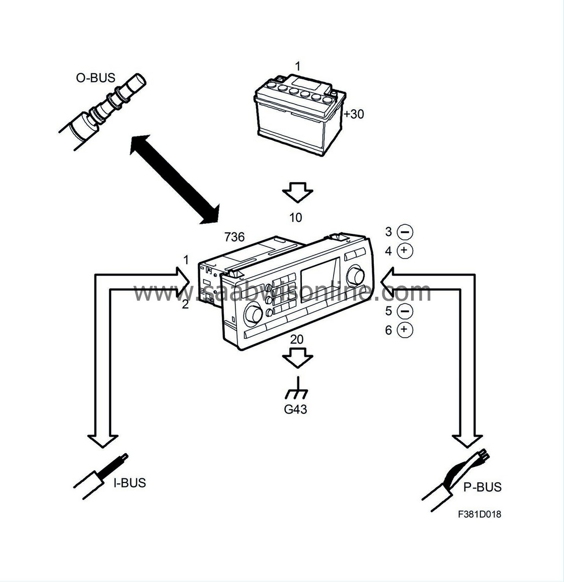
Pin no.
|
Signal type
|
Description
|
|
-
|
O-bus (input)
|
sleeve 1 is the optical signal input
|
|
-
|
O-bus (output)
|
sleeve 2 is the optical signal output
|
|
1
|
I-bus
|
|
|
2
|
I-bus
|
|
|
3
|
P-bus (-)
|
|
|
4
|
P-bus (+)
|
|
|
5
|
P-bus (-)
|
|
|
6
|
P-bus (+)
|
|
|
10
|
Ground
|
Grounding point G43
|
|
20
|
+30 supply
|
From instrument panel main fuse box (22) pin 14 via fuse 14.
|
Power supply and ground
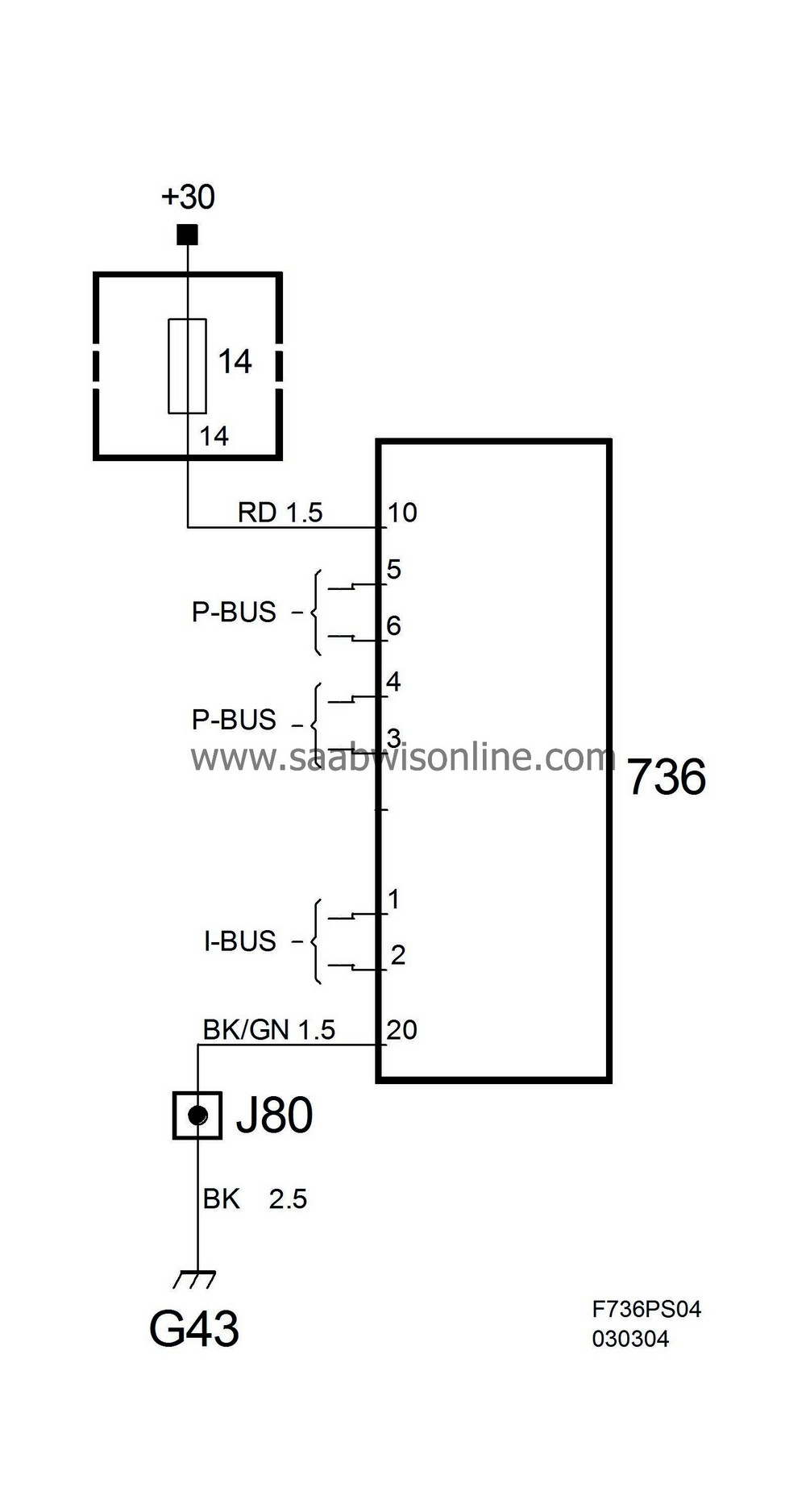
The control module can be woken up by
|
•
|
Wake-up signal (12V) on I-bus
|
|
•
|
Button press on SID control panel
|
The connectors are identical for all three control module variants. The fibre optic cables of the O-bus are connected to two plastic sockets, where socket 1 receives and socket 2 transmits. The control module is connected to the P and I-buses.
ICM communicates with SID through a 2-wire communication cable and a wake-up signal of 5V.
ICM communicates with SIDC with PWM signals. ICM powers SIDC with 5V and has a lead for the wake-up signal (5V) and a lead for system ground.


