PRE-RELEASE
Fuel
| Fuel |
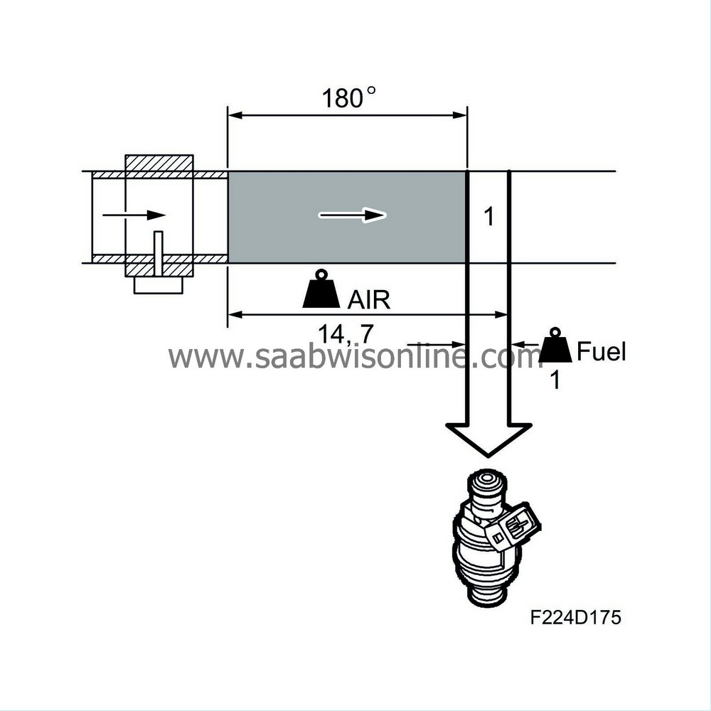
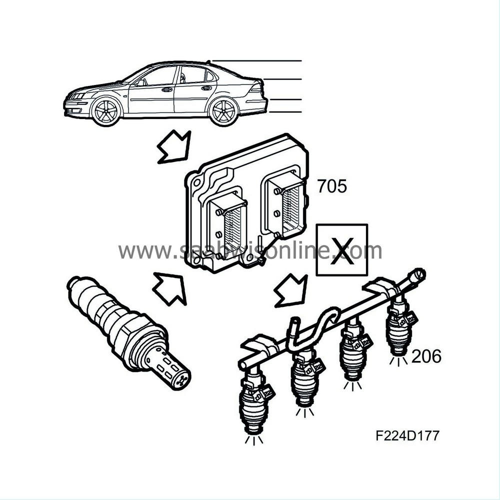
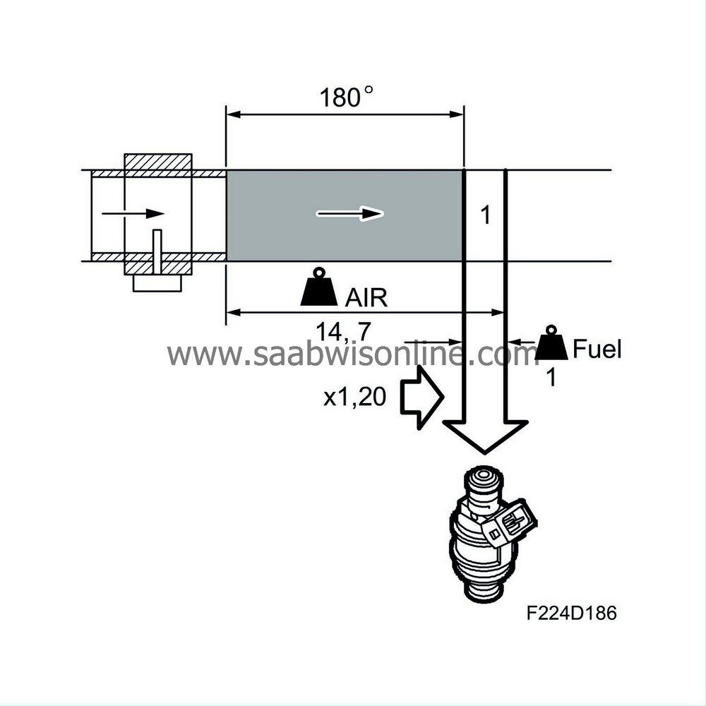
Most interesting, however, is how much air mass is drawn into each cylinder, since it is to this are the petrol will be added. The control module registers the air mass drawn in during one engine revolution. Since the engine is 4-cylinder 4-stroke, two cylinders must have drawn in air simultaneously during the one engine revolution. The air mass passing the mass air flow sensor is divided by two, which means the control module knows the amount each cylinder has drawn in. The unit is now changed to milligrams air/combustion (mg/c).
To attain lambda = 1, the fuel and air must have a special ratio, namely 1 kg fuel to 14.7 kg air. Since the amount of air drawn into each cylinder/combustion is known, the control module can easily calculate how much fuel to injection into the cylinders on each occasion. Milligram air/combustion is divided by 14.7 and the result is mg petrol/combustion to be injected in the cylinder.
The following text is an account of why the basic fuel quantity must sometimes be adjusted to a leaner, or most often, a slightly richer mixture so that the engine will run smoothly and emissions will be kept within required limits.
Basic fuel quantity
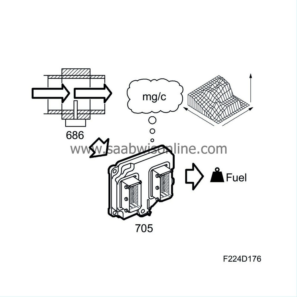
The mass air flow sensor value converted to air mass per combustion is corrected using a matrix (map) to compensate the volumetric efficiency (VE). In this function, there is also a full-load enrichment used to increase engine torque and to cool the engine and catalytic converter.This gives the value "basic fuel mass".
Fuel adaptation
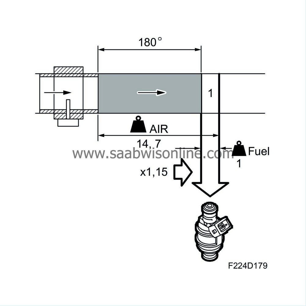
To compensate for e.g. manufacturing tolerances, ageing, etc., continuous deviations from lambda 1.00 are adapted. Fuel adaptation is divided into two sub-functions, multiplicative (partial load) and additive (idling). Together, these adaptations will make the closed loop work with a correction factor of around 1.00.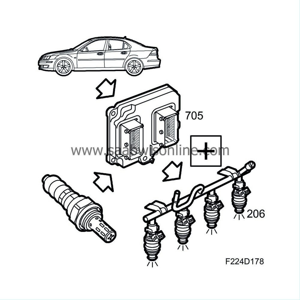
Multiplicative fuel adaptation
If the closed loop is continuously correcting a deviation in the fuel system, it will be adapted. Adaptation takes place regularly while driving.The fuel quantity is always multiplied by a multiplicative adaptation factor of 1.00 when the control module is new or has had its power disconnected. Multiplicative adaptation takes place under conditions of partial load. Purging is stopped during adaptation because other factors that can affect the fuel must not be active.
The total closed loop deviation from 1.00 is transferred to the multiplicative adaptation factor. This means the right amount of fuel is injected even though closed loop is not active, for example when cold starting or driving with full load. A multiplicative adaptation must always take place before an additive after starting the engine.
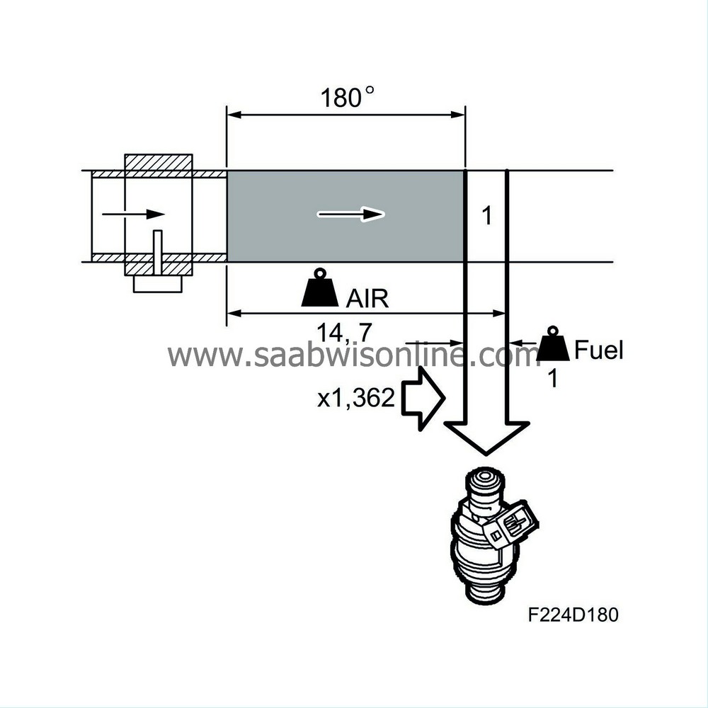
Additive fuel adaptation
If the closed loop is continuously correcting a deviation in the fuel system, it will be adapted. Adaptation takes place regularly at idling speed. The additive adaptation, which is 0.000 ms injection duration when the control module is new or has had its power disconnected, is always added to the fuel amount. The additive adaptation takes place at idling speed. Purging is stopped during adaptation because other factors that can affect the fuel must not be active.The fuel quantity is added or subtracted until closed loop fluctuates around 1.00 (0%). Additive adaptation is required because air leaks at idling speed will lead to a greater fault that must not be adapted multiplicatively as the fuel quantity would then be far too great when the load was increased.
Warm up enrichment
Warm up enrichment is carried out to compensate for the extra fuel a cold engine needs. The time for this enrichment is dependent on the coolant temperature.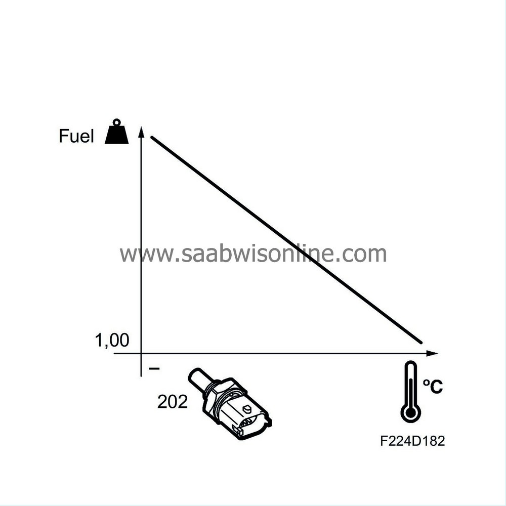
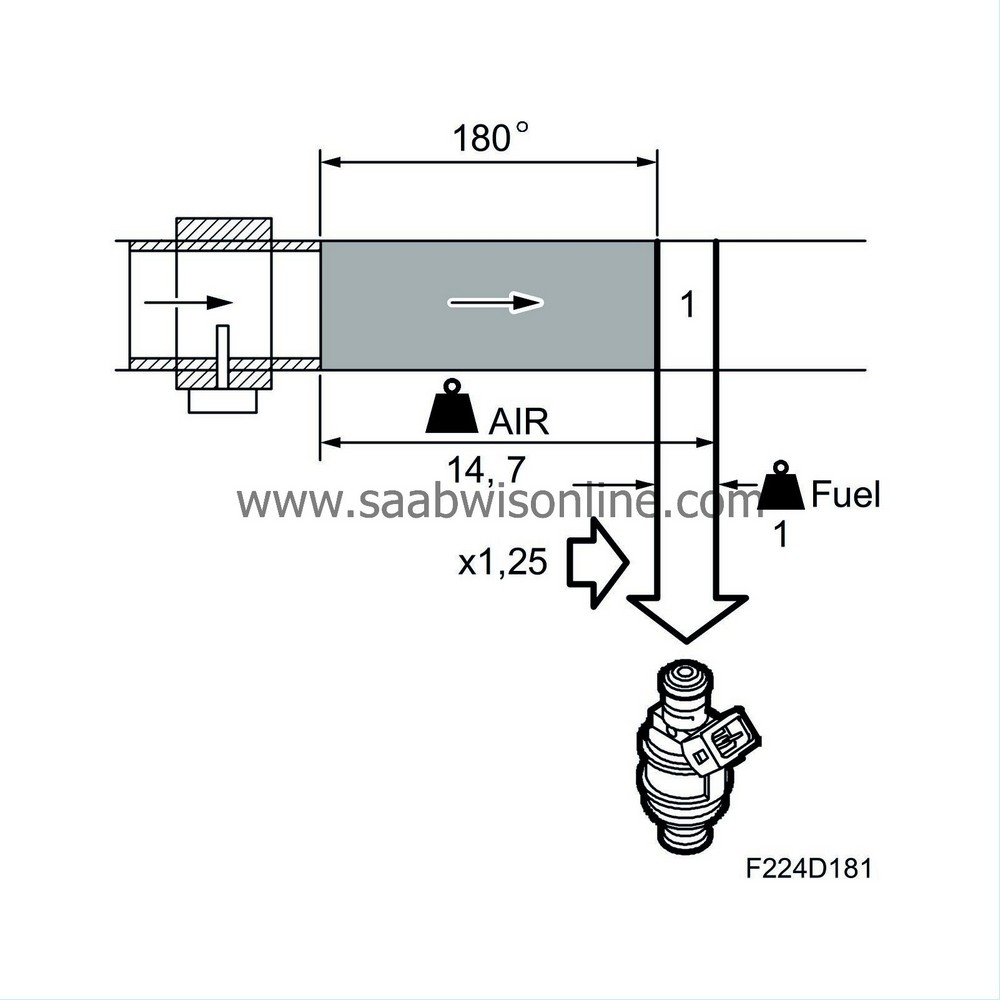
Catalytic converter warm up compensation
Principally, this function is an offset to "warm up enrichment". It is done to warm up the catalytic converter as quickly as possible. The function counteracts the enrichment at high load resulting from the "warm up enrichment" function. This will warm up the catalytic converter quicker.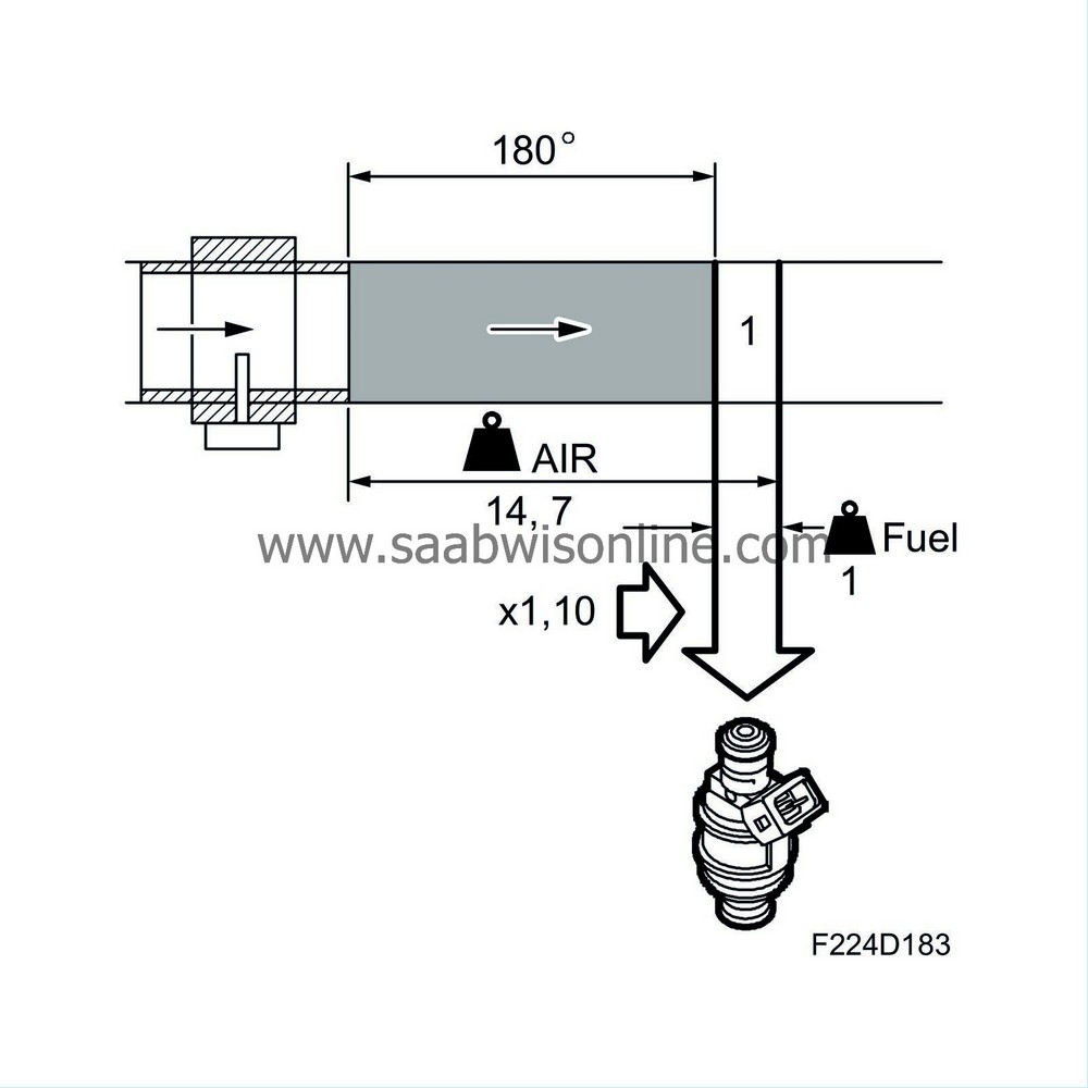
After start enrichment
Immediately after starting the engine, the correction factor is slightly over 1 and then falls gradually to 1.00. The extent to which the correction factor exceeds 1 and the time it takes to reach 1.00 again depend on the coolant temperature. On cars with carburettor engines, this function is the choke. The closed loop starting criteria are such that it starts just when fuel enrichment after starting has dropped to 1.00.
Purging adaptation
The fuel which evaporates in the tank is passed through a pipe to the evaporative emission canister. The active charcoal in the canister absorbs the hydrocarbon vapours. When the engine starts, ambient air is drawn through the canister via the purge valve into the intake manifold. The petrol vapours follow with it and are burned in the engine.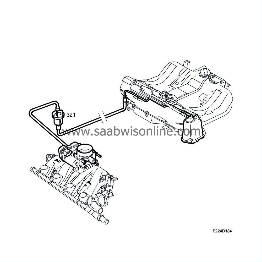
The flow is regulated by the pulse conditions so that is always constitutes a particular proportion of the total flow consumed by the engine.
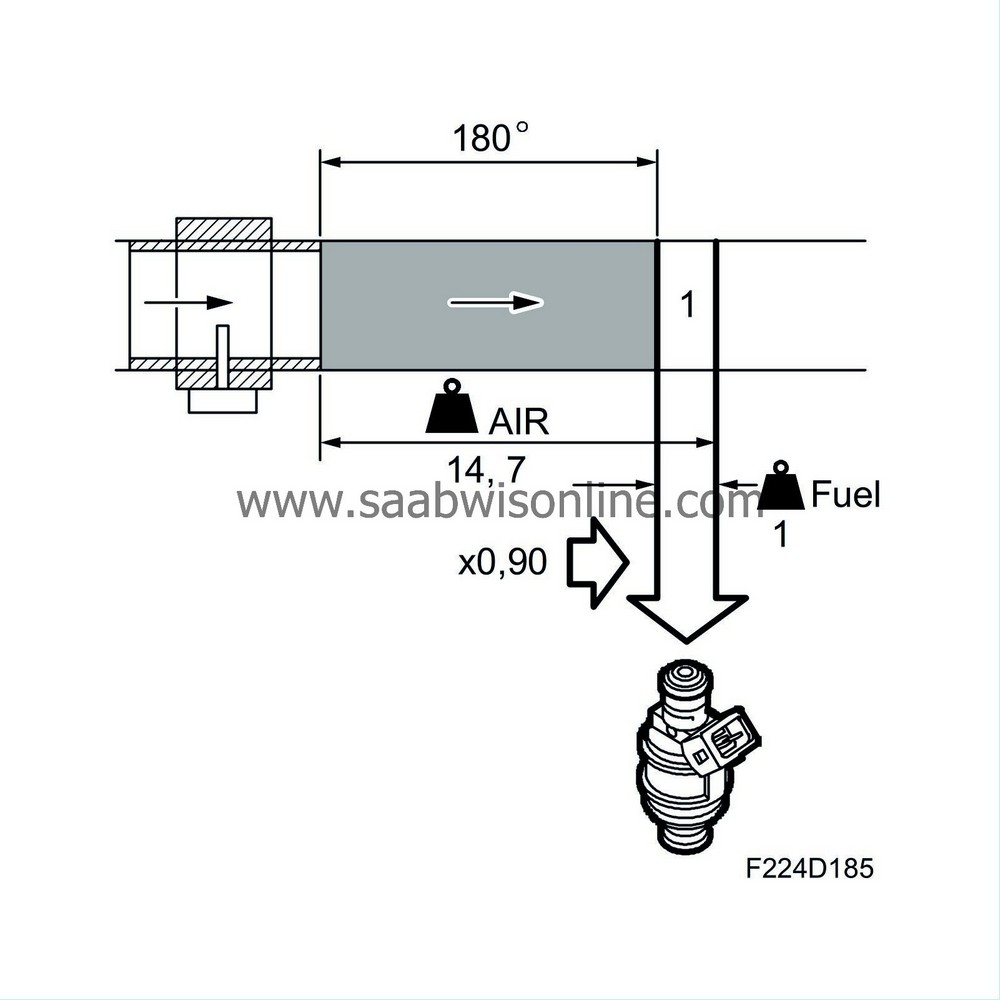
If the air/fuel ratio of the flow differs from 14.7:1, the closed loop system is affected. However it is not the task of the closed loop system to correct for purge surplus and therefore the purge has a correction factor which is influenced by the closed loop system as soon as the purge begins. The entire lambda control deviation from 1.00 is moved to the purge correction factor, which means that the lambda control fluctuates around 1.00 (0%) even if the purge contains large quantities of hydrocarbon or consists of pure air.
When the purge is not active, a factor of 1.00 is used and the entire fuel error corrected by the closed loop system and the multiplicative and additive adaptation
Load changes
A sudden load increase causes the mg air/combustion to increase rapidly and it is well known that petrol engines then require a richer mixture. This is because fuel is deposited on the walls of the intake manifold due to the increase in pressure there, and the wet-film thickness increases. The fuel quantity used here must be replaced by a slightly larger quantity of injected fuel, which is achieved by increasing the correction factor by a few percentage points. For example, the correction factor can be increased from 1.00 to 1.03, which gives 3% more fuel.As soon as the load increase stops, the correction factor returns to its original value.
The function works conversely for a load reduction. The wet film that is deposited on the walls of the intake manifold evaporates quickly in conjunction with a drop in pressure. The amount of fuel injected must then be reduced so that emissions and fuel consumption are not affected negatively. This is done by reducing the correction factor a few percentage points. For example, the correction factor can be reduced from 1.00 to 0.96 to give 4% less fuel.
On a car with a carburettor engine, the function described above corresponds to the accelerator pump or damper piston.
Compensation for a non-return system
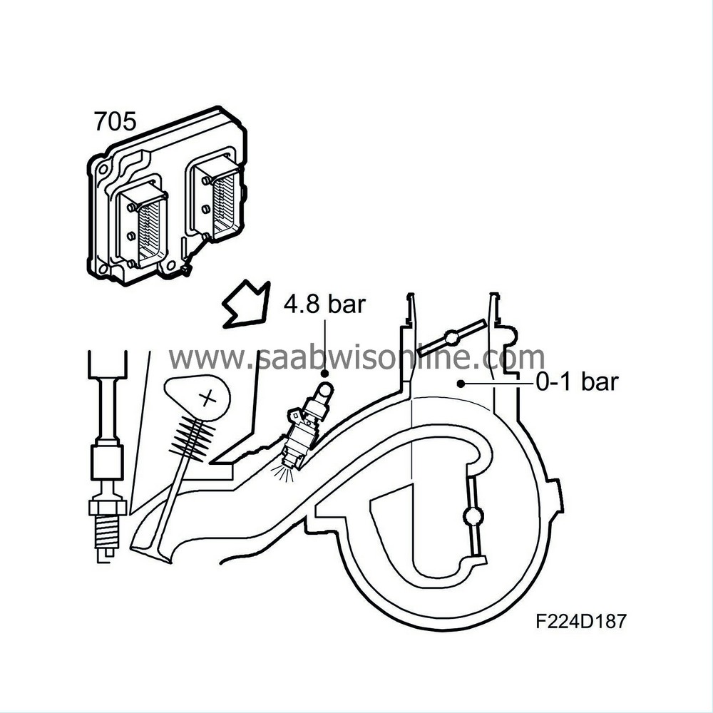
The flow of the injector valves is determined by the opening duration and differential pressure across the nozzle. The opening duration is governed by ECM. The differential pressure is fuel pressure - intake pressure and will consequently vary with engine load, or rather intake pressure.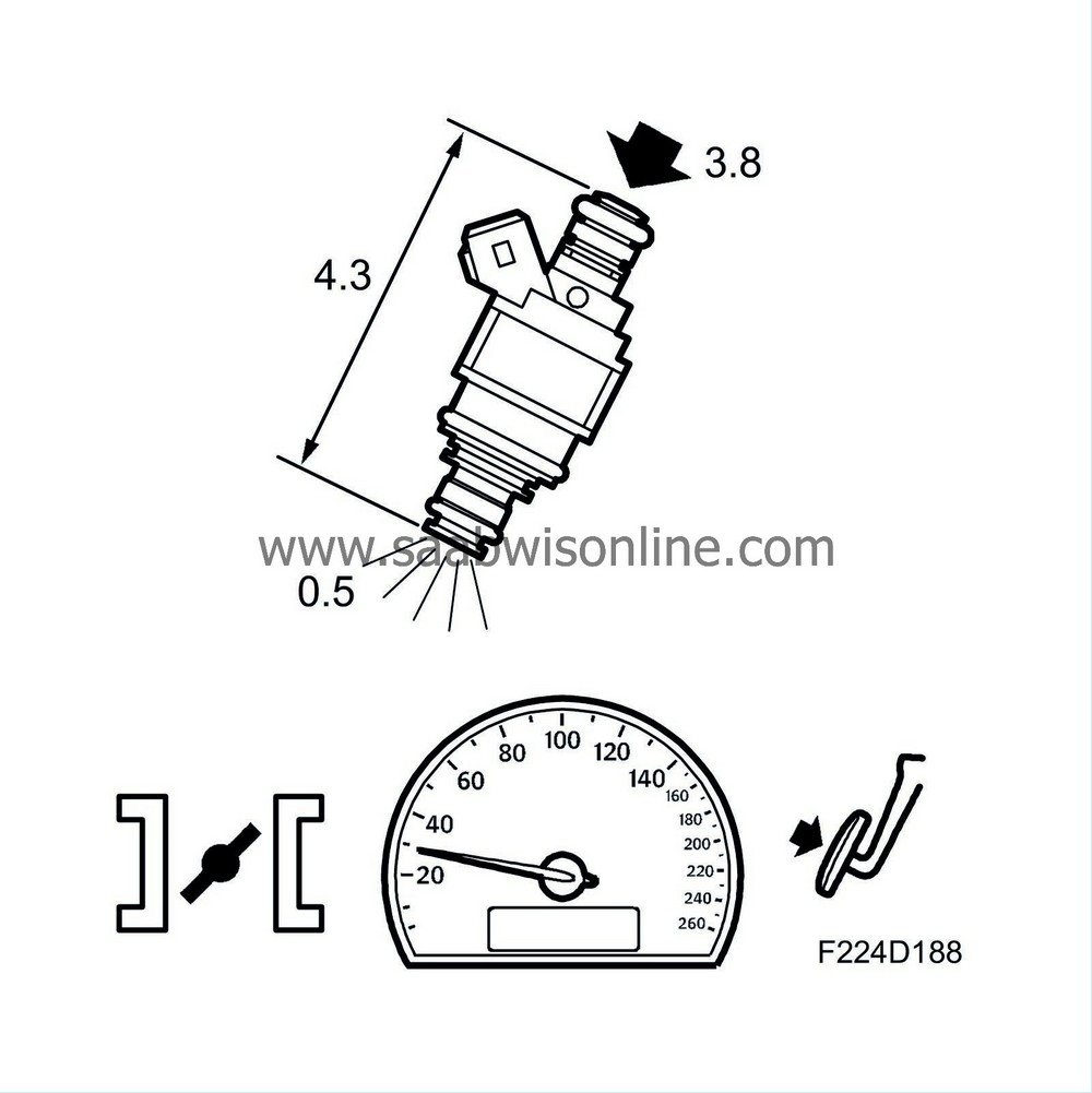
Example with light engine load: Fuel pressure 3.8 bar and Intake pressure -0.5 bar = Differential pressure 4.3 bar.
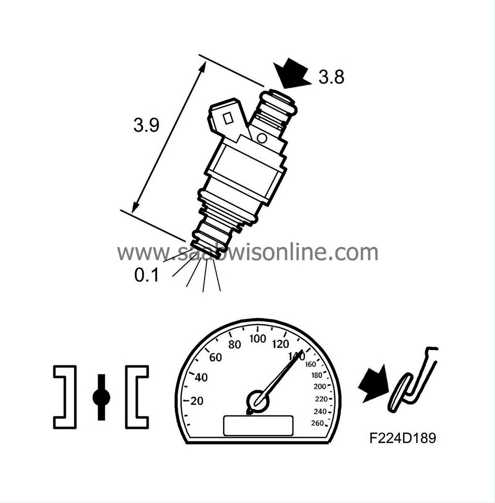
Example with high engine load: Fuel pressure 3.8 bar and Intake pressure -0.1 bar = Differential pressure 3.9 bar.
Example with high engine brake: Fuel pressure 3.8 bar and Intake pressure -0.8 bar = Differential pressure 4.6 bar.
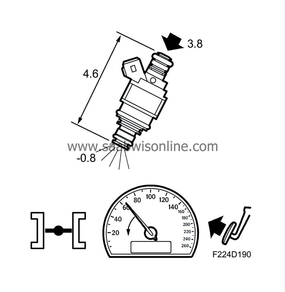
The examples above show clearly how the differential pressure is affected by the intake pressure. If the injectors are to deliver the correct amount of fuel, the injection timing must be compensated for the varying differential pressure.
ECM calculates the pressure prevailing in the intake manifold and consequently there is no pressure sensor.
Needle lift compensation
The voltage-dependent needle lift time is added to the injection time. This compensates for the delay between activation of the current in the injector coil and supply of the fuel.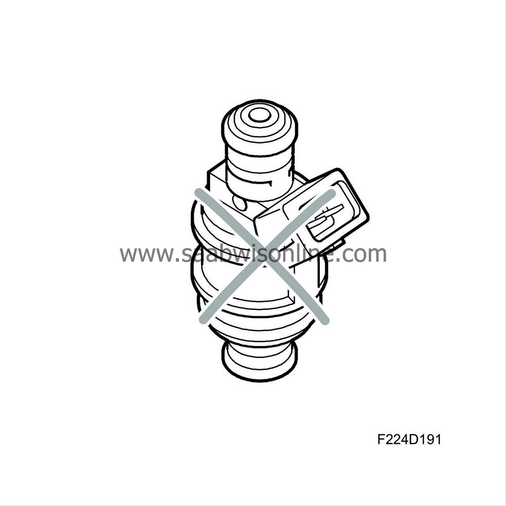
Fuel shut-off
Under certain conditions, e.g. on engine braking or car immobilised, the fuel cut-off can apply. The injection timing is then zero.Activating the injectors
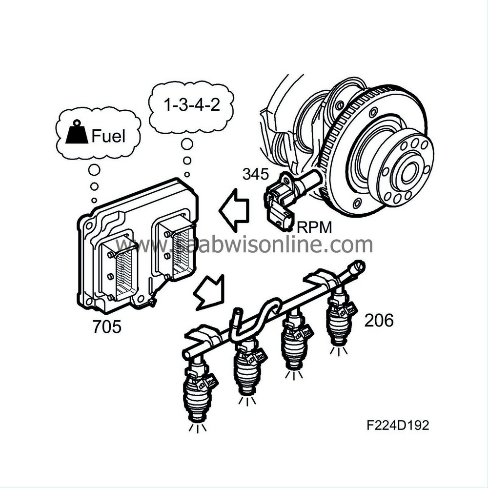
ECM controls the injector that is about to deliver fuel. This sequence is determined by the firing order. It is the prevailing running conditions that determine the crankshaft angles at which injection is to take place. Normally, injection is completed around the time the inlet valve for the current cylinder opens.