(371-2637 utg 2) Replacing the wiring harness
Symptom: Diagnostic trouble codes that may be generated: C0040 2A, C0040 01, C0040 06, C0040 29.
The warning lamp in the MIU may illuminate together with a text message in the SID:
- Antilock brake malfunction. Contact service.
- Traction control failure. Contact service.
- Stability control failure. Contact service.
- Steering lock malfunc. Make a safe stop. Contact service.
|
MODIFICATION INSTRUCTION
|
|
Bulletin Nbr:
|
371-2637 utg 2
|
|
Date:
...........
|
Februari 2007
|
|
Market:
|
ej US/CA
|
|
|
Replacing the wiring harness
|
|
Customer Satisfaction Program 154 51
|
Cars in stock must be rectified before delivery.
A personal communication must be sent to the owners of cars already delivered requesting them to get in touch with the nearest Saab garage as soon as possible to have the fault rectified.
Saab 9-3 M06 within Vehicle Identification Number range:
4D/5D:
61008030 - 61111559
CV:
66002261 - 66100050
The crimp on the wiring harness for the right-hand front wheel sensor is not waterproof. This could result in corrosion in the wheel sensor's connector.
Symptom description
Diagnostic trouble codes that may be generated: C0040 2A, C0040 01, C0040 06, C0040 29.
The warning lamp in the MIU may illuminate together with a text message in the SID:
- Antilock brake malfunction. Contact service.
- Traction control failure. Contact service.
- Stability control failure. Contact service.
- Steering lock malfunc. Make a safe stop. Contact service.
79 71 864 Cable tie,
LHD:
x 14,
RHD:
x 15.
12 771 828 Wiring harness, wheel sensor (RHD)
12 771 829 Wiring harness, wheel sensor (LHD)
Contact Protect CRC (www.crcindustries.com) or Contact 61 or similar
Heat resistant fabric tape
For fitting the modification identity plate (not US/CA):
12 785 148 Modification identity plate
93 160 907 Cleaning agent Motip Dupli, aerosol 400 ml (sufficient for 50-100 cars)
|
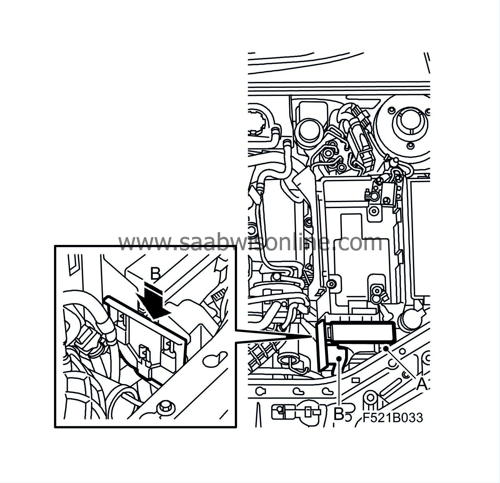
Checking the modification identity plate (not US/CA)
|
Before proceeding, check box B5 of the modification identity plate. From and including M04 the car's Warranty and Service Book contains the "Table of Modifications". A modification identity plate must be fitted in accordance with the section "Fitting the modification identity plate" where local directives require the marking of the car. If the box is not marked, continue as follows.
|
Procedure - Z18XE, B207, B284, Z19 manual
|
|
Note
|
|
The procedure for the Z19 automatic is described separately below.
|
|
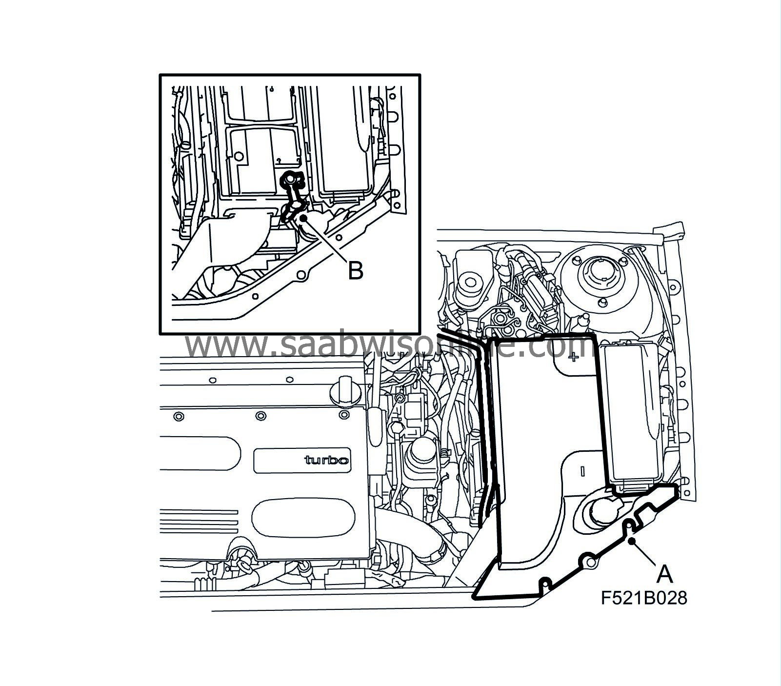
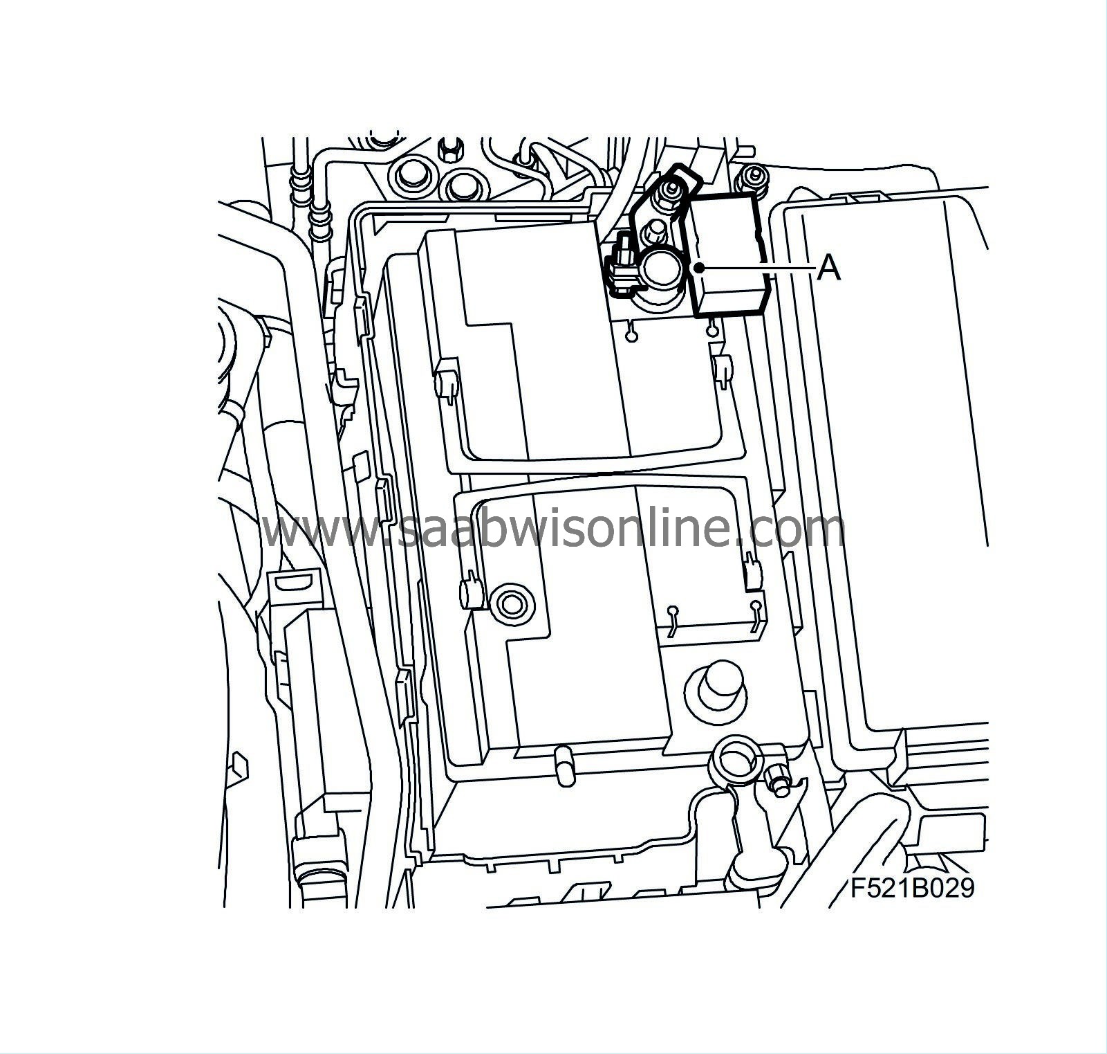
2.
|
Remove the battery cover (A) and undo the battery's negative cable (B).
|
|
3.
|
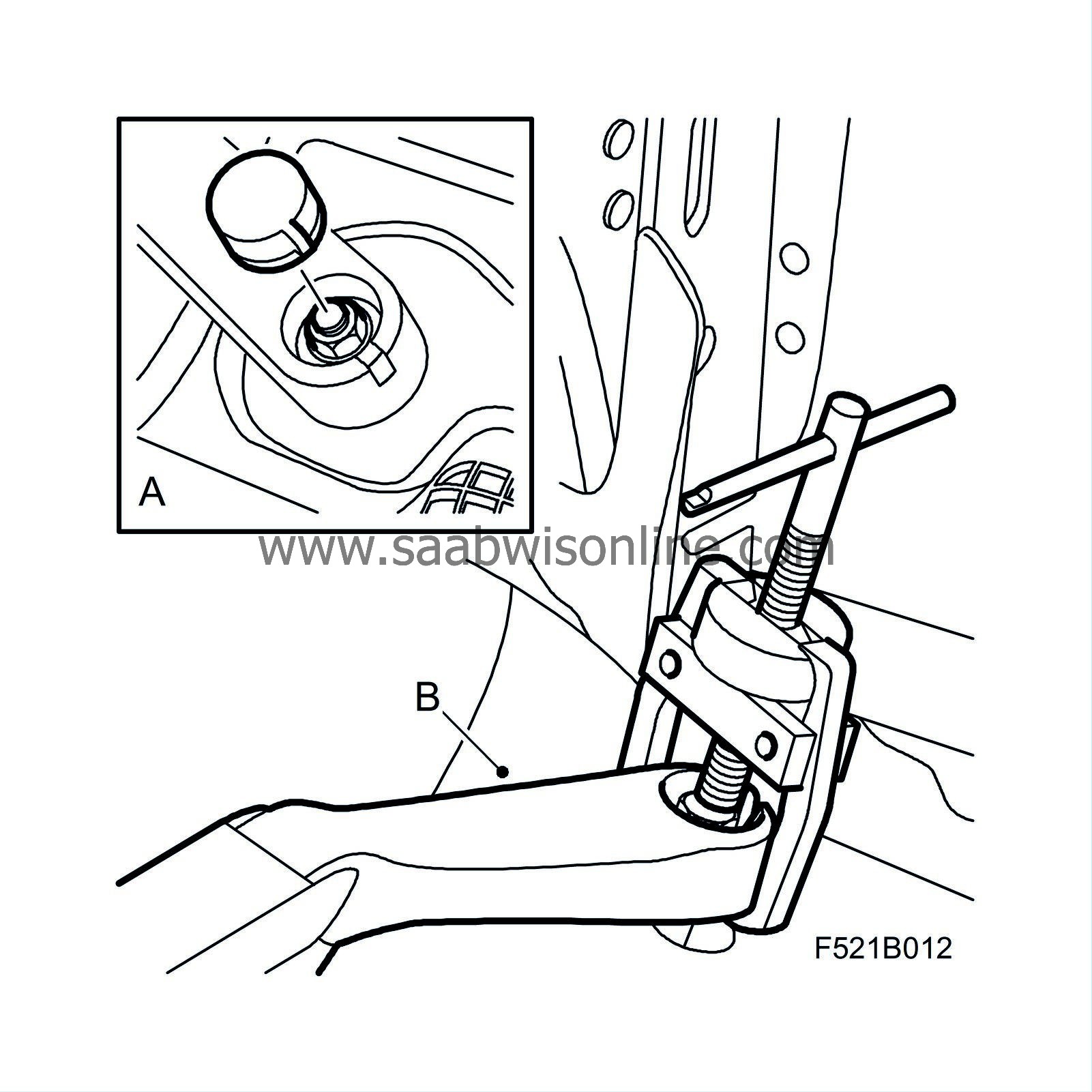
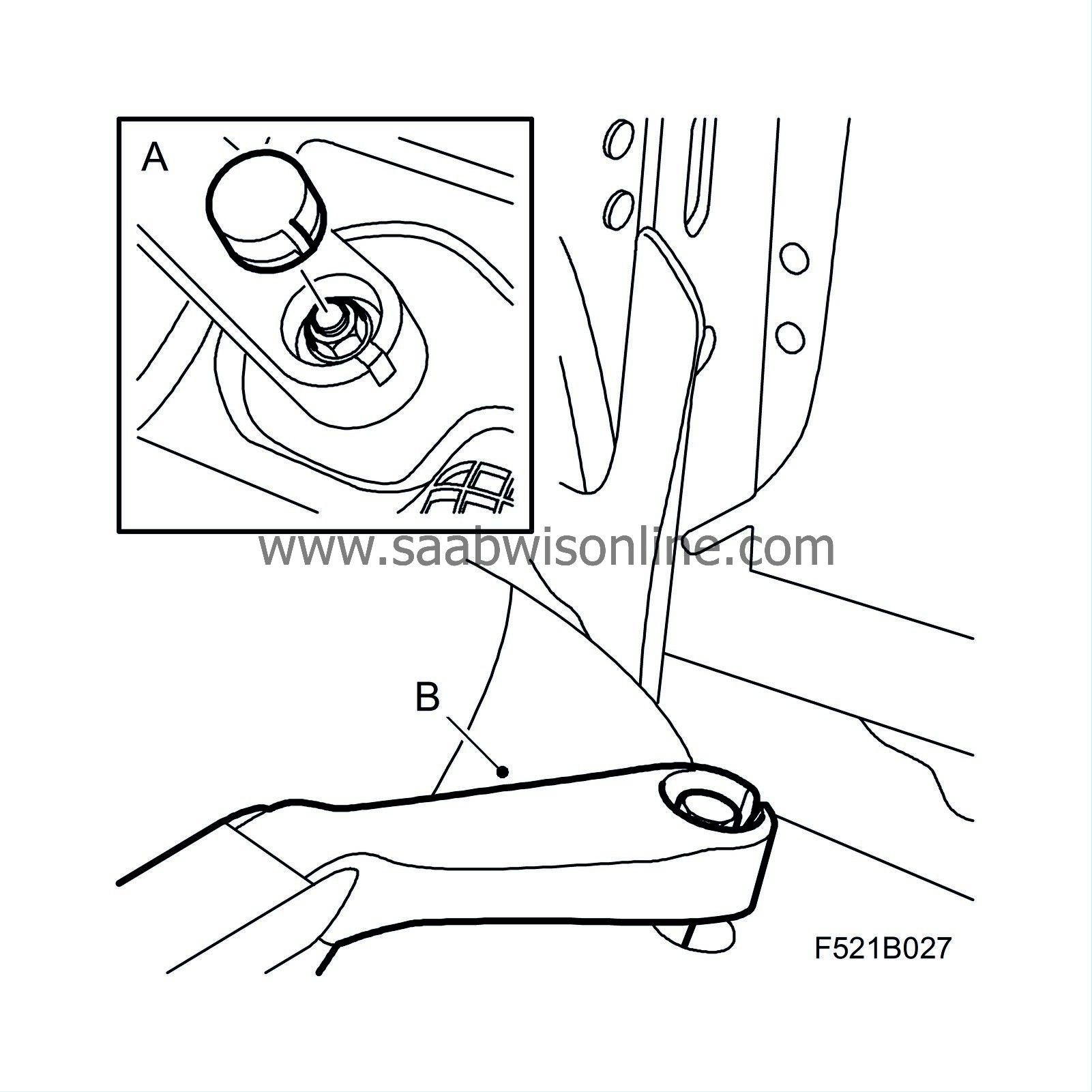
Remove the wiper arms:
|
|
|
•
|
Remove the protective covers (A) from the wiper arms' retaining nuts.
|
|
|
•
|
Remove the wiper arms (B), use 85 80 144 Puller, windscreen wiper arm.
|
|
4.
|
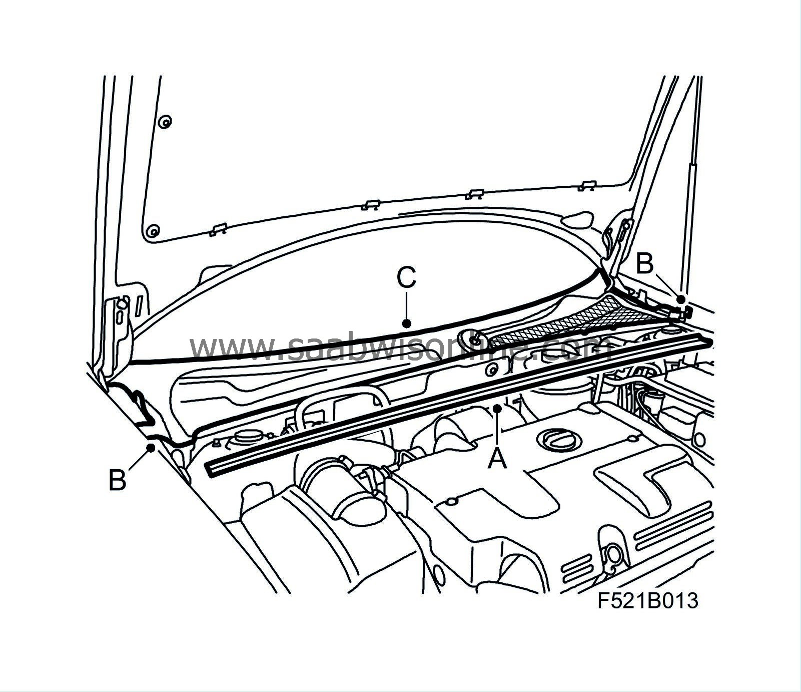
Remove the cover and water barrier:
|
|
|
•
|
Remove the rear bonnet seal (A).
|
|
|
•
|
Remove the cover's clips (B).
|
|
|
•
|
Start to remove the cover (C) from the right-hand side: lift away the foam block and lift up the front edge of the cover so that the hook and the clips release, bend the corner tab aside. Continue with the left-hand side and undo the clips and the hook under the windscreen. Lift the cover away.
|
|
|
•
|
Remove the water barrier (D).
|
|
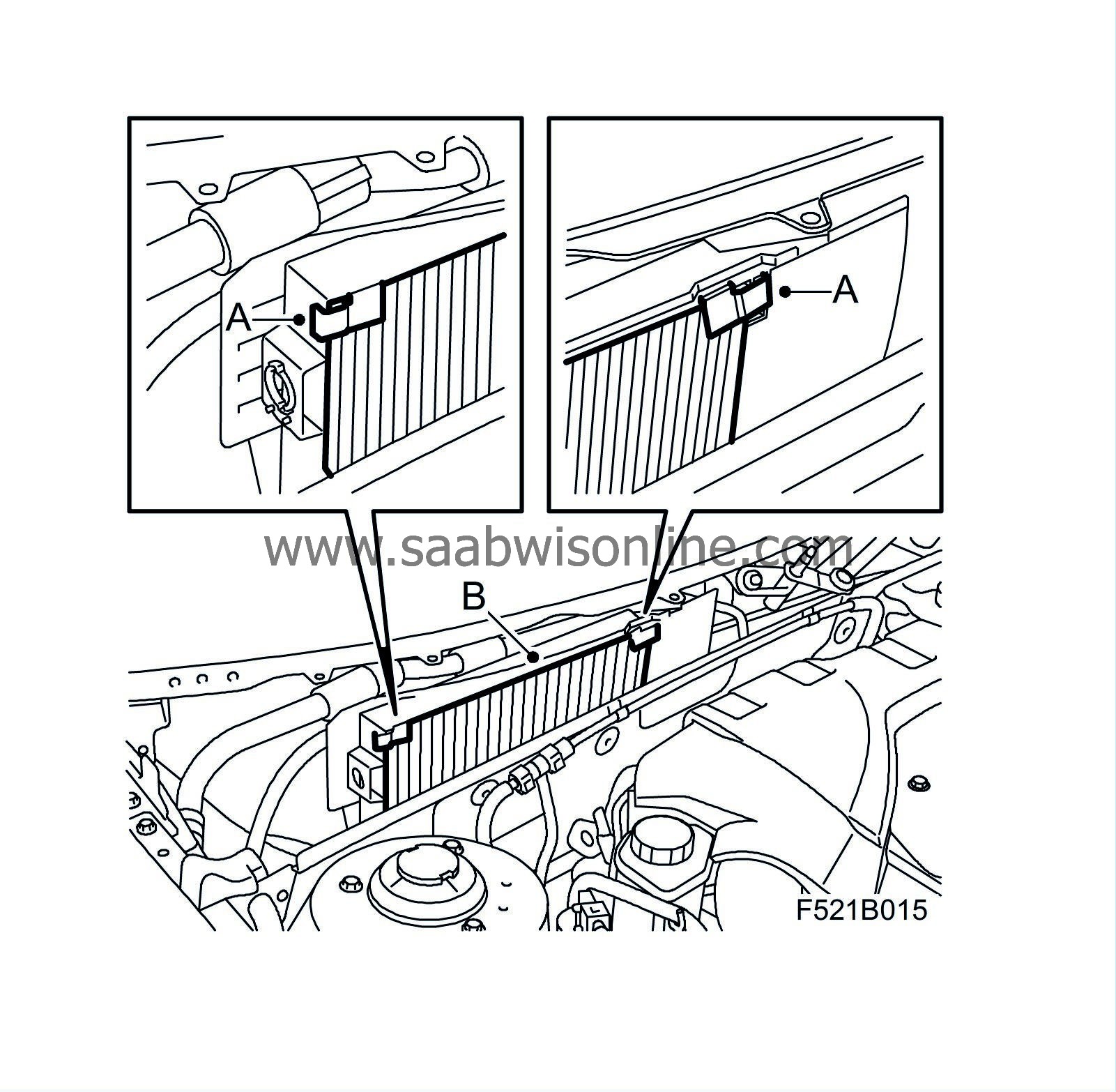
5.
|
Fold the clip (A) up from the filter holder and lift off the compartment filter (B).
|
|
6.
|
Lift up the wiring harness, which is placed under the filter holder. Dismantle the rubber grommet (A) and cut the cable tie (B). Remove the tape from around the rubber grommet.
|
|
7.
|
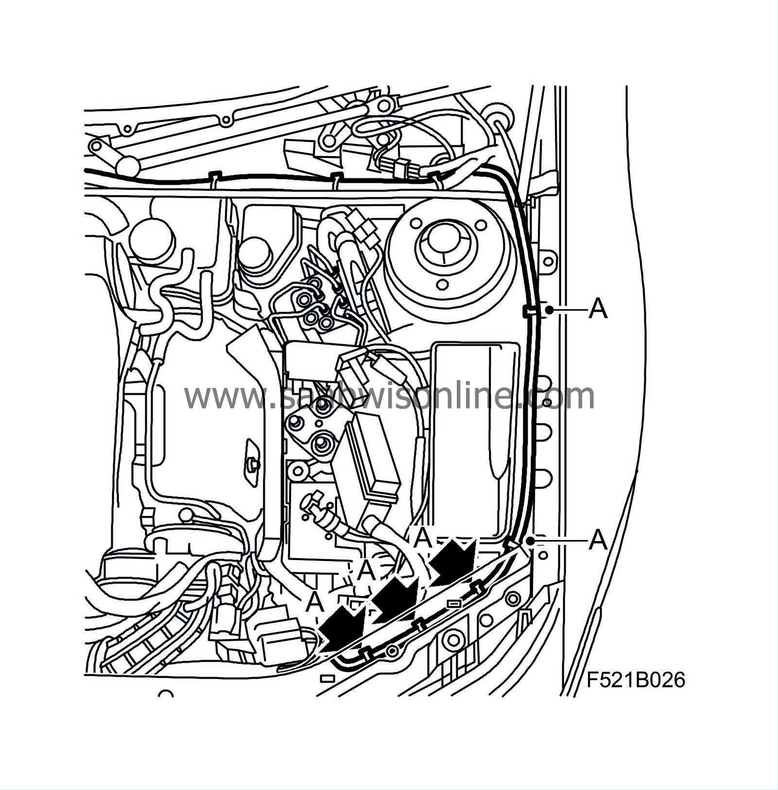
Route the new wheel sensor cable down along the structural member next to the damaged wheel sensor cable.
|
|
8.
|
Raise the car and angle the wheels to the right.
|
|
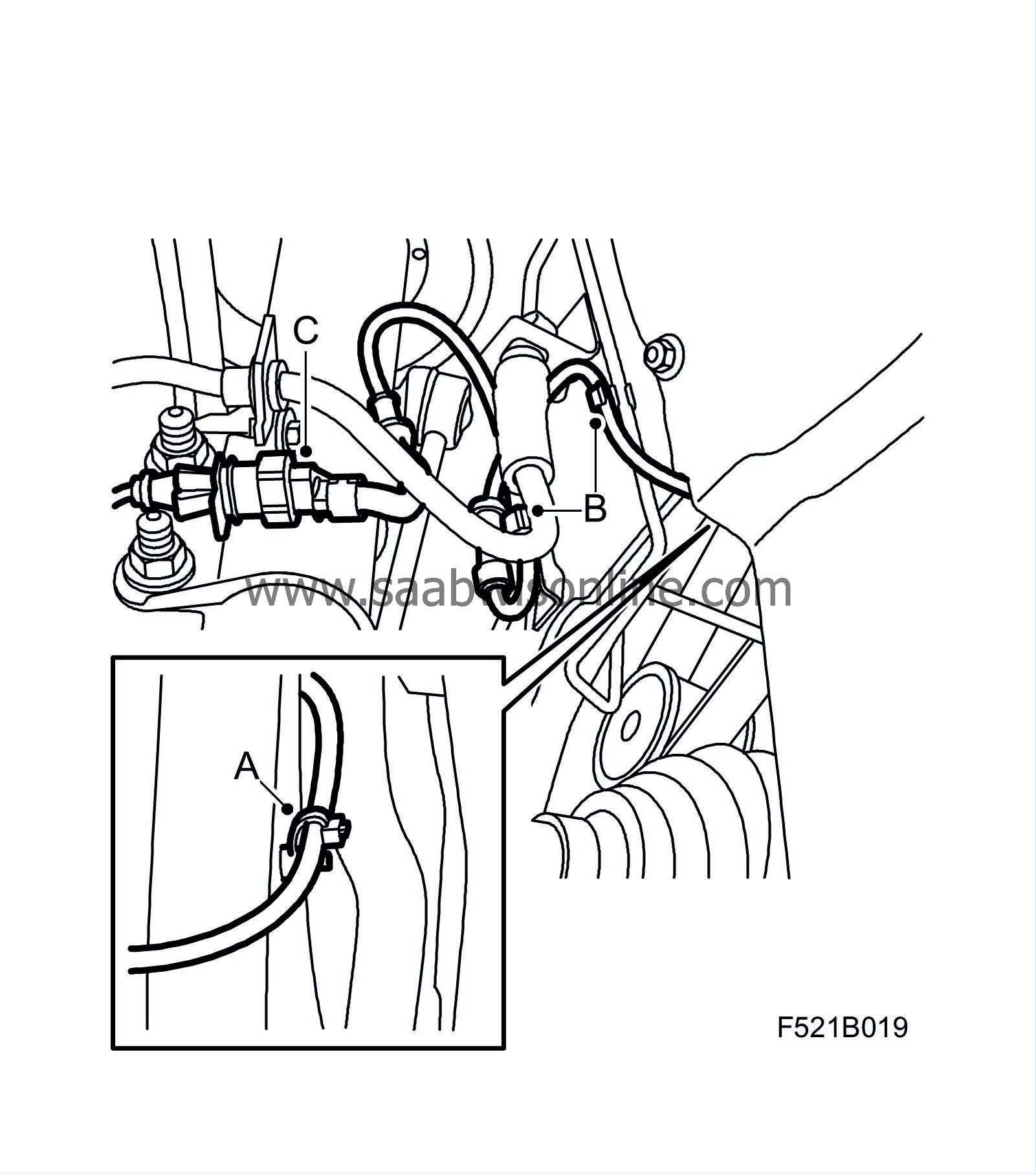
9.
|
Remove the damaged wheel sensor cable from the structural member and the wheel housing:
|
|
|
•
|
Remove the clip (A) from the structural member.
|
|
|
•
|
Remove the wheel sensor cable from the mountings (B).
|
|
|
•
|
Unplug the connector (C).
|
|
10.
|
Fit the wheel sensor cable to the structural member and the wheel housing:
|
|
|
•
|
Fit the wheel sensor cable to the mountings (B).
|
|
|
•
|
Clean any corrosion from the wheel sensor's connector housing (C). Use contact 61.
|
|
|
•
|
Spray the connector housing (C) with Contact 61 and connect the connector housing.
|
|
|
•
|
Fit the clip (A) to the structural member from below.
|
|
12.
|
Cut off the damaged wheel sensor cable at the entry to the wiring harness coil.
|
|
13.
|
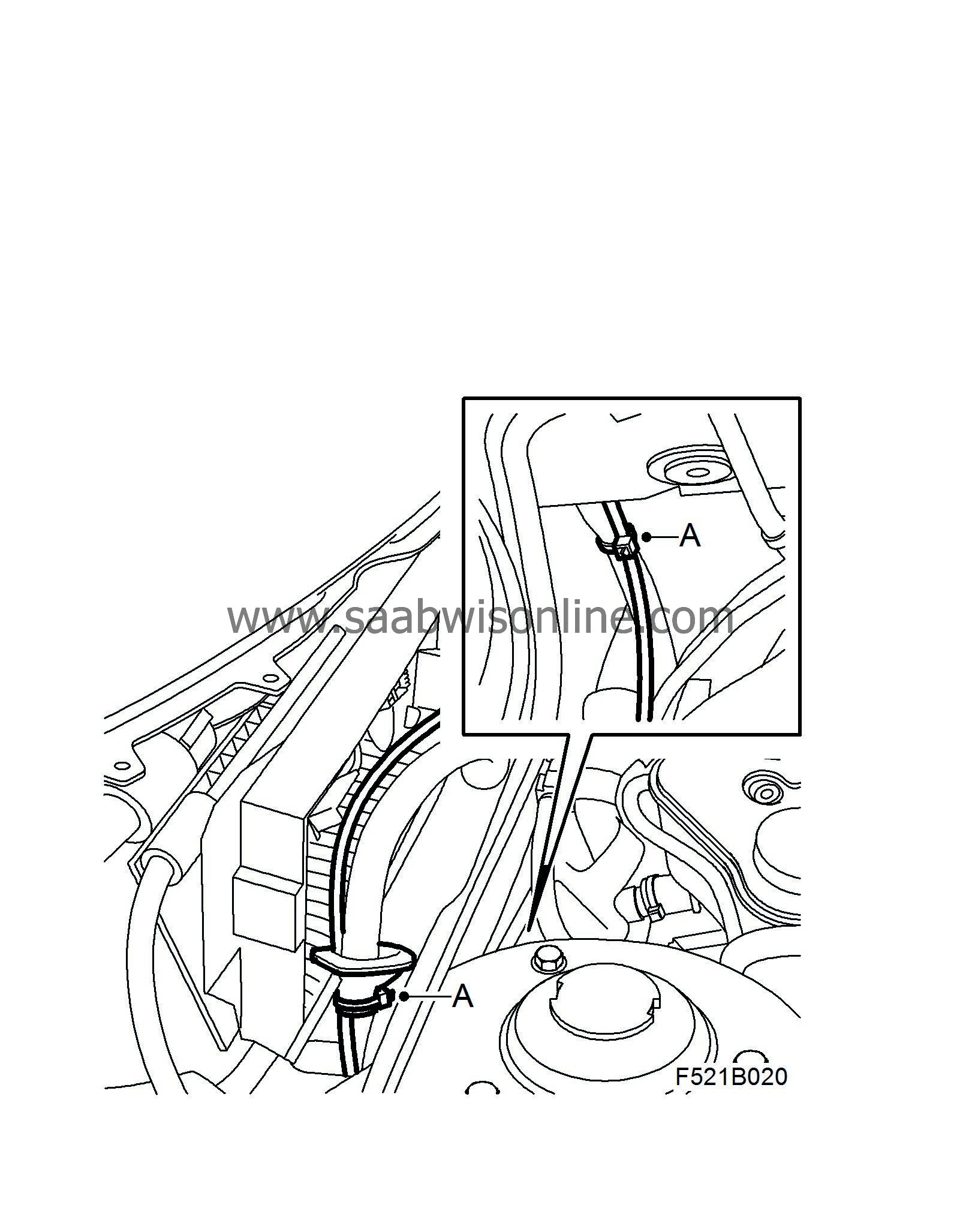
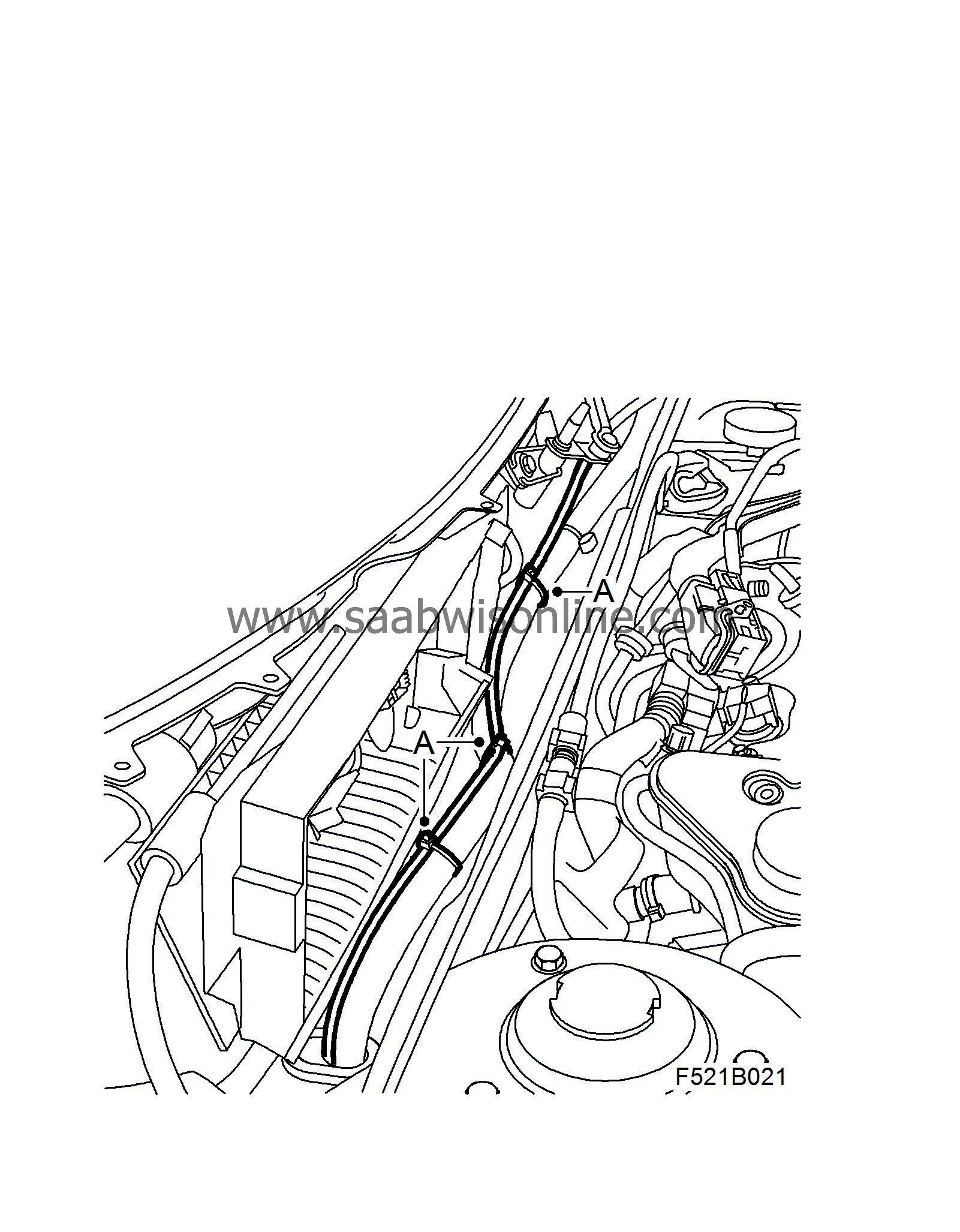
Align and secure the wheel sensor cable to the right-hand side:
|
|
|
•
|
Route the wheel sensor cable up along the wiring harness, through the rubber grommet and on along the wiring harness.
|
|
|
•
|
Secure the wheel sensor cable (A) to the wiring harness. Use heat resistant fabric tape around the rubber grommet and fit the rubber grommet. Reposition the wiring harness under the filter holder.
|
|
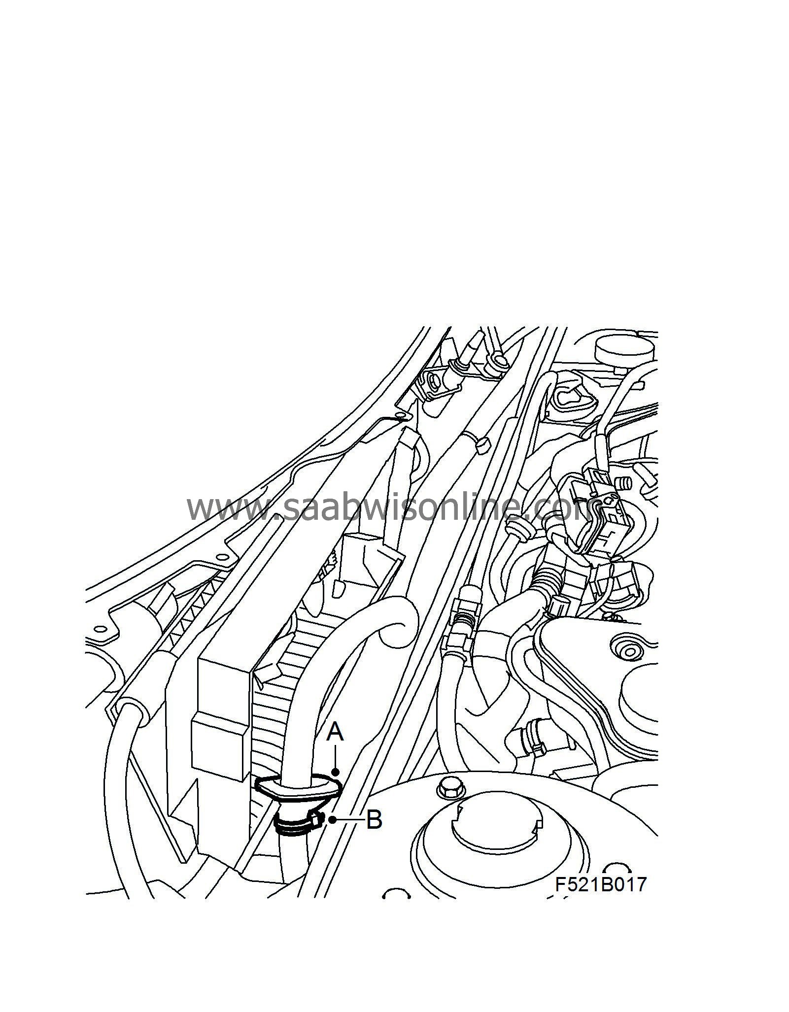
14.
|
Align and secure the wheel sensor cable to the left-hand side:
|
|
|
•
|
Remove the rubber grommet (A) and cut the cable tie (B). Remove the tape around the rubber grommet.
|
|
|
•
|
Route the wheel sensor cable along the wiring harness, through the rubber grommet and on along the wiring harness.
|
|
|
•
|
Secure the wheel sensor cable (A) to the wiring harness.
|
|
|
•
|
Use heat resistant fabric tape around the rubber grommet and fit the rubber grommet.
|
|
15.
|
B207, B284, Z19 manual, CV:
Raise the car
|
Note
|
|
Z18XE:
Steps 15-18 are carried out from above.
|
|
|
16.
|
Prepared connection of the wheel sensor cable:
|
|
|
•
|
CV with engine alternative Z19:
Remove the chassis reinforcement, front subframe in accordance with WIS - Suspension, wheels - Front suspension.
|
|
|
•
|
Z19 manual:
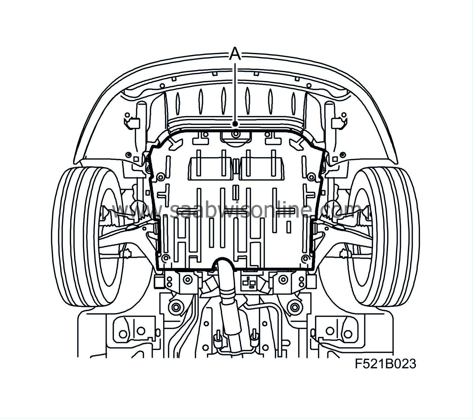
Remove the lower engine cover (A).
|
|
|
•
|
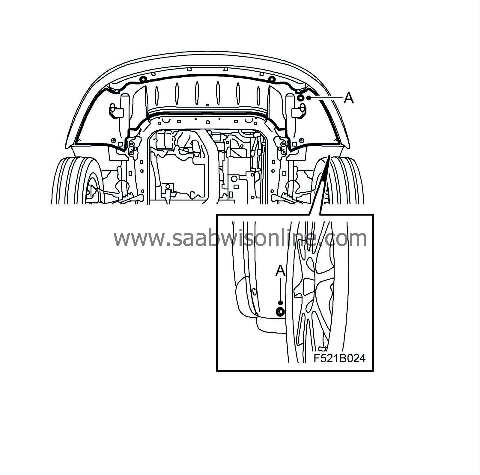
B207, B284, Z19 manual, CV:
Remove the two outer screws (A) to the spoiler shield on the left-hand side & fold down the spoiler shield.
|
|
|
•
|
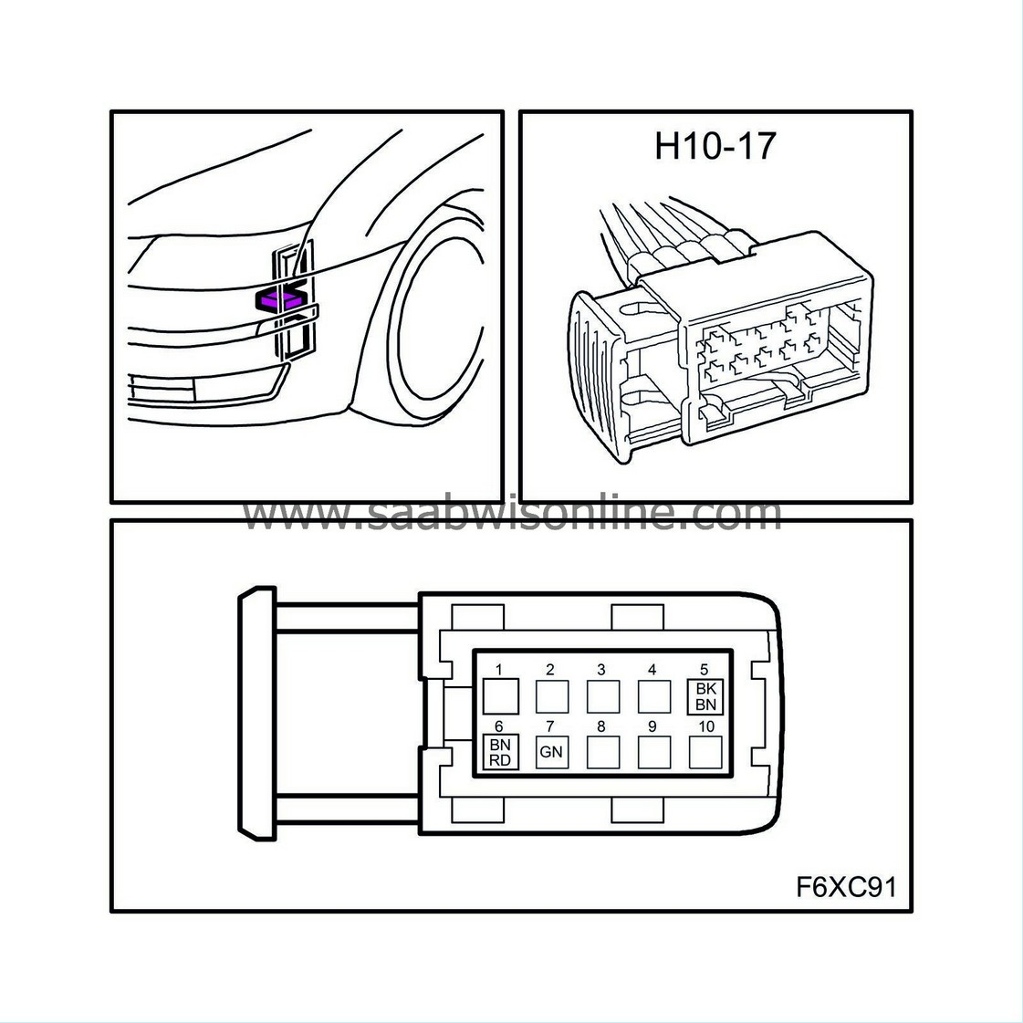
B284:
Unplug connector H10-17 (blue connector).
|
|
|
•
|
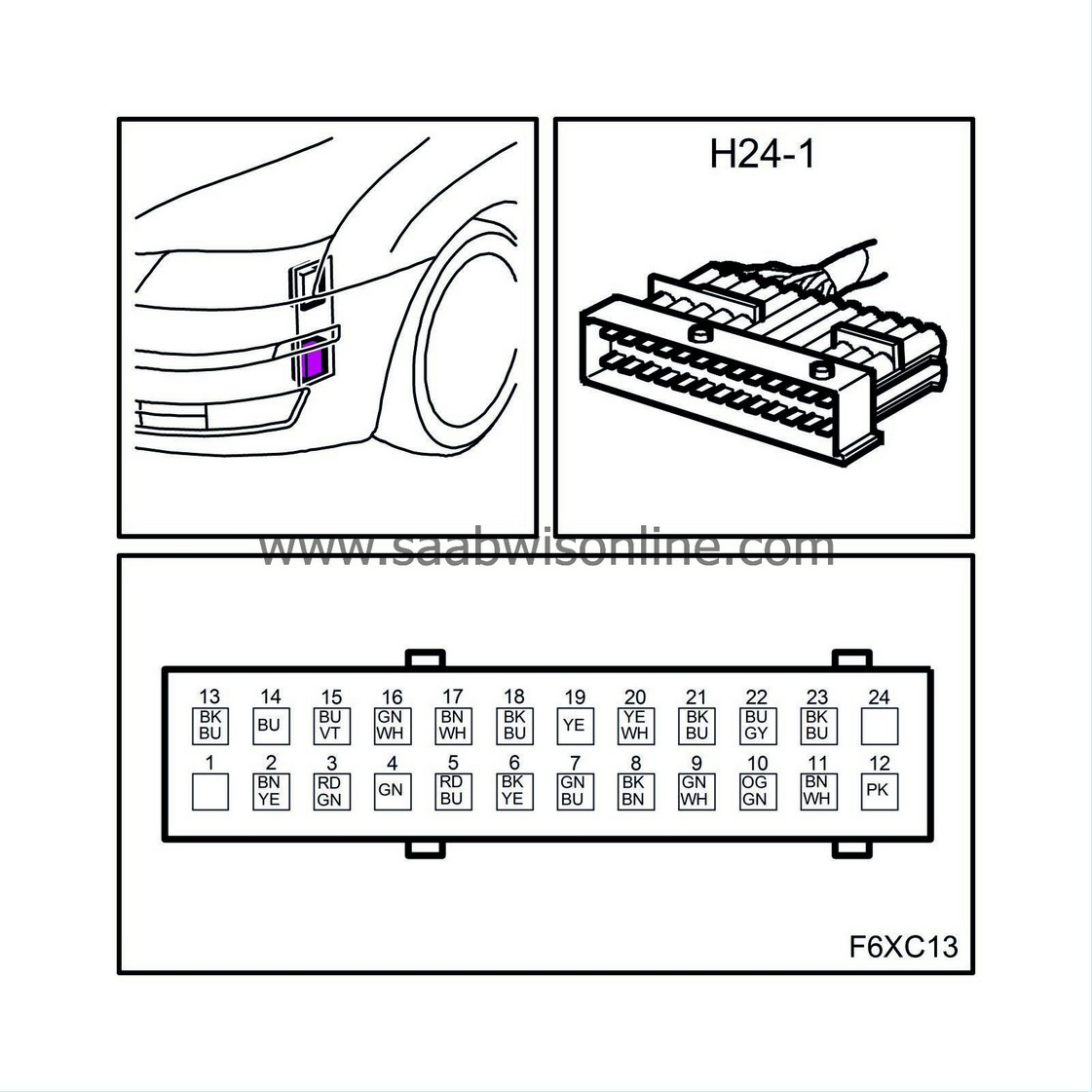
Remove the bracket for connector H24-1 (black connector) from the structural member.
|
|
|
•
|
Unplug connector H24-1 (A) and remove it from the bracket (B).
|
|
17.
|
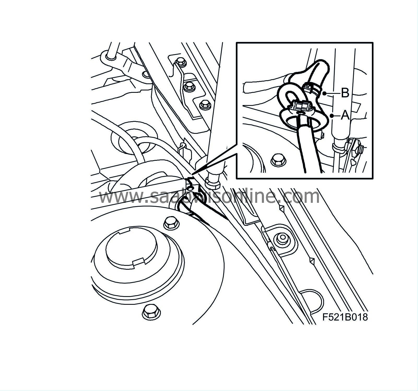
Connect the wheel sensor cable to connector H24-1:
|
|
|
•
|
Remove the seal in the connector.
|
|
|
•
|
Remove pin 5 and pin 6, use the extraction tool, 85 80 151.
|
|
|
•
|
Connect the wheel sensor cable's brown conductor to pin 5 and the black conductor to pin 6. Check that the sleeves are firmly locked and that they are at the same depth as other sleeves.
|
|
|
•
|
Fit the seal in the connector.
|
|
|
•
|
Fit connector H24-1 (A) to the bracket (B) and plug it in.
|
|
18.
|
Refit the prepared connection of the wheel sensor cable:
|
|
|
•
|
Fit the bracket for connector H24-1 to the structural member.
|
|
|
•
|
B284:
Plug in connector H10-17 (blue connector).
|
|
|
•
|
Z19 manual:
Fit the lower engine cover (A).
|
|
|
•
|
CV with engine alternative Z19:
Fit the chassis reinforcement, front subframe in accordance with WIS - Suspension, wheels - Front suspension.
|
|
|
•
|
B207, B284, Z19 manual, CV:
Fold up the spoiler shield and fit the screws (A).
|
|
19.
|
B207, B284, Z19 manual, CV:
Lower the car
|
|
20.
|
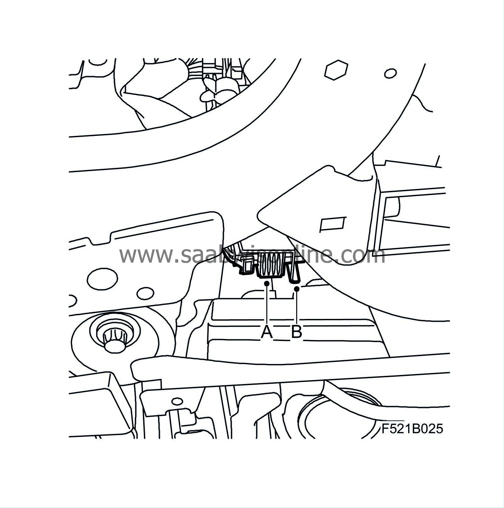
Remove the fuse box (A).
B284:
Remove the fuse holder (B).

|
|
21.
|
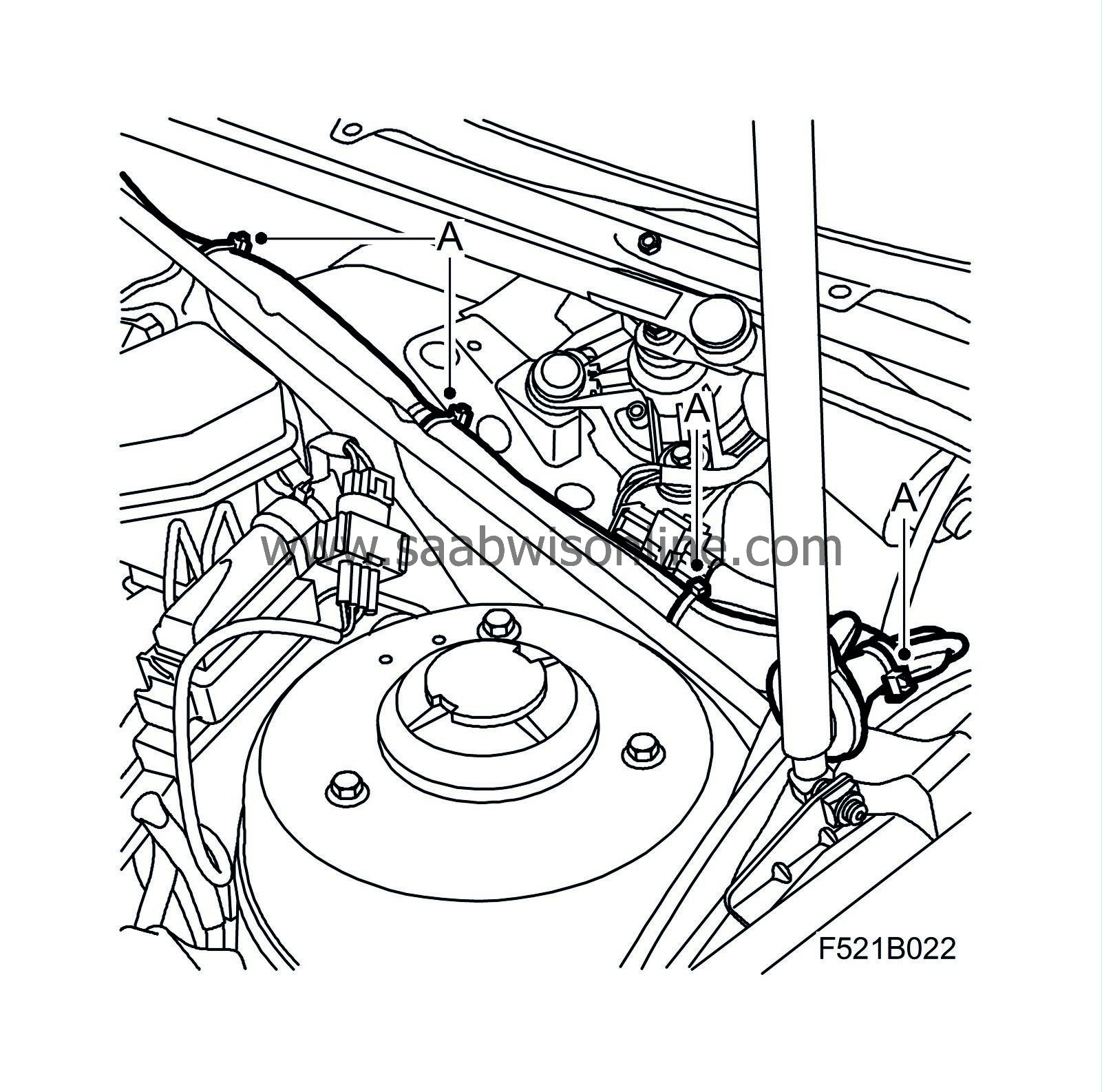
Secure the wheel sensor cable adjacent to the existing cable ties (A).
|
|
22.
|
Fit the fuse box (A).
B284:
Fit the fuse holder (B).
|
|
23.
|
Fit the compartment filter (B) and secure the clip (A).
|
|
24.
|
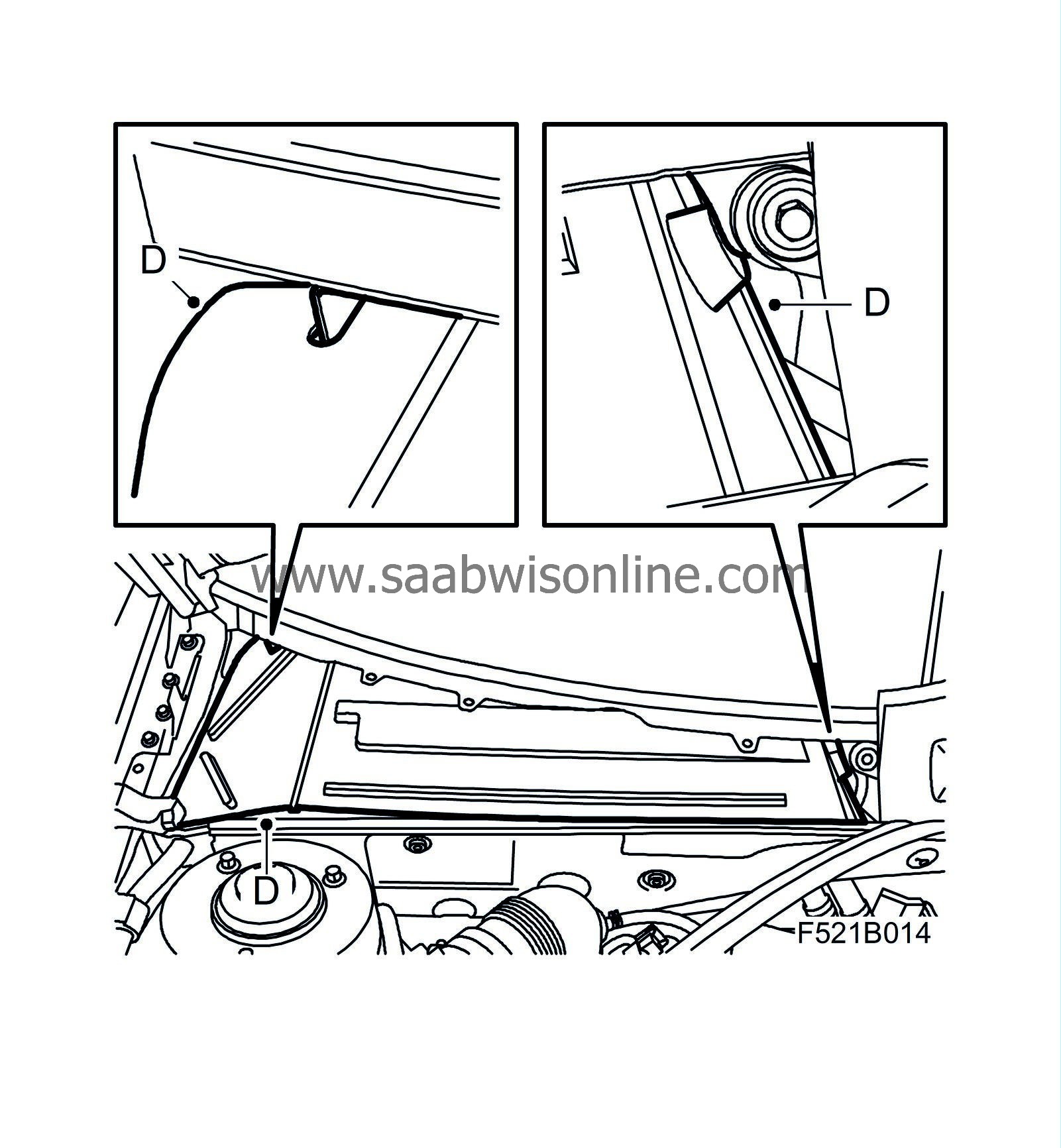
Fit the water barrier and cover:
|
|
|
•
|
Fit the water barrier (D).
|
|
|
•
|
Align the cover (C) and start to fit it from the left-hand side. Guide in the corner against the windscreen trim and the left-hand wiper spindle. Lift the foam block away and insert the hook under the windscreen. Align the cover against the right-hand wiper spindle. Fold down the corner tab so that it passes the hinge and bonnet. Align the corner tab under the windscreen trim. Insert the hook under the windscreen and press the cover down so that the clips engage.
|
|
|
•
|
Lift up the foam blocks and fit the clips (B).
|
|
|
•
|
Remove the rear bonnet seal (A).
|
|
25.
|
Fit the wiper arms:
|
|
|
•
|
Fit the wiper arms (B).
|
|
|
•
|
Fit the protective covers (A).
|
|
26.
|
Fit the battery's negative cable (B) and the battery cover (A).
|
|
27.
|
Carry out "Procedures after disconnecting the battery" in accordance with WIS - Electrical System - Wiring harness and components - Wiring harness.
|
|
28.
|
Clear any diagnostic trouble codes.
|
|
29.
|
Road test and check that no diagnostic trouble codes recur.
|
|
Procedure - Z19 automatic
|
|
2.
|
Remove the battery cover (A) and undo the battery's negative cable (B).
|
|
3.
|
Undo the battery's positive cable (A).
|
|
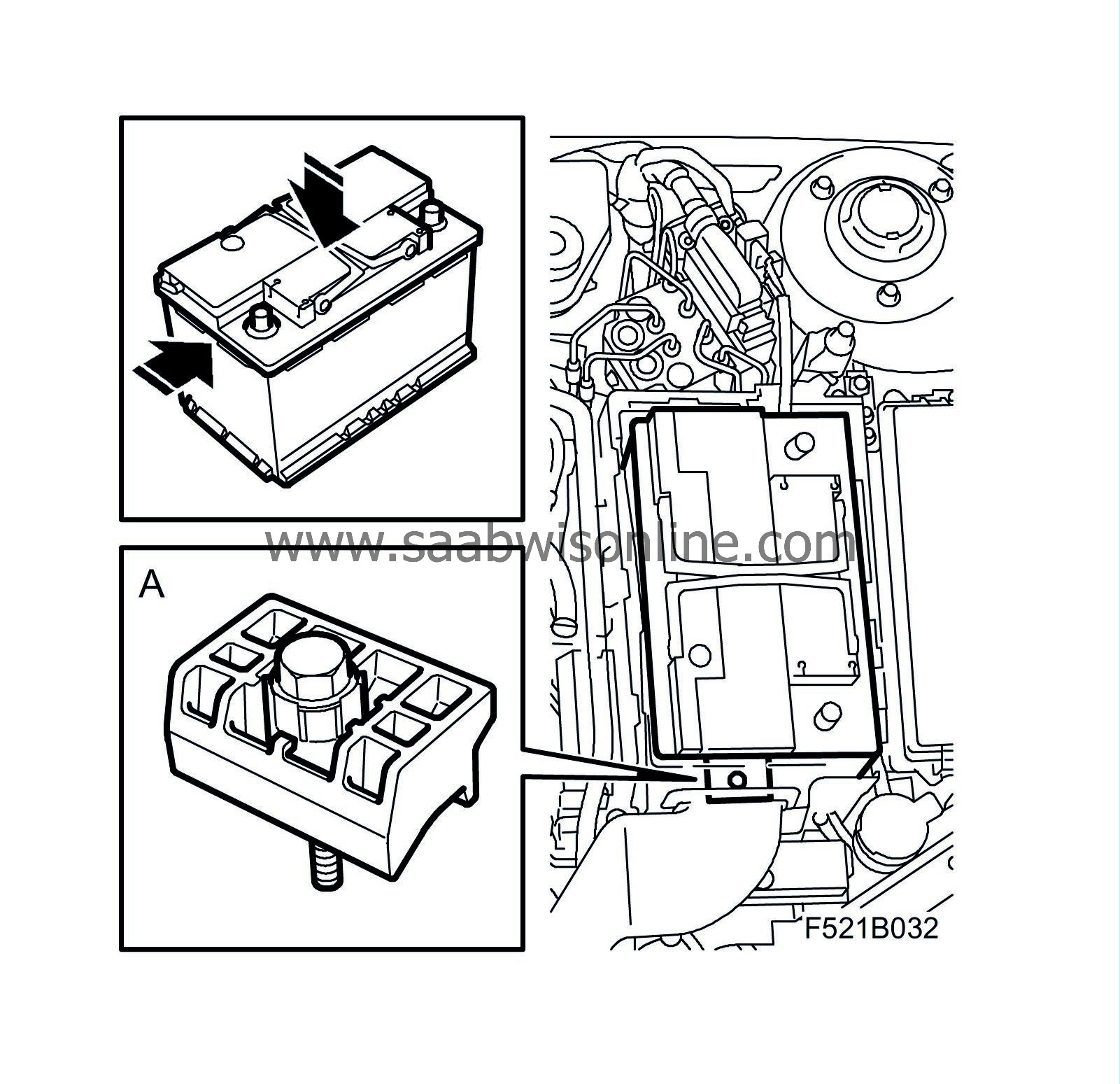
4.
|
Undo the screw (A) to the battery's lock lug and lift out the battery.

|
|
5.
|
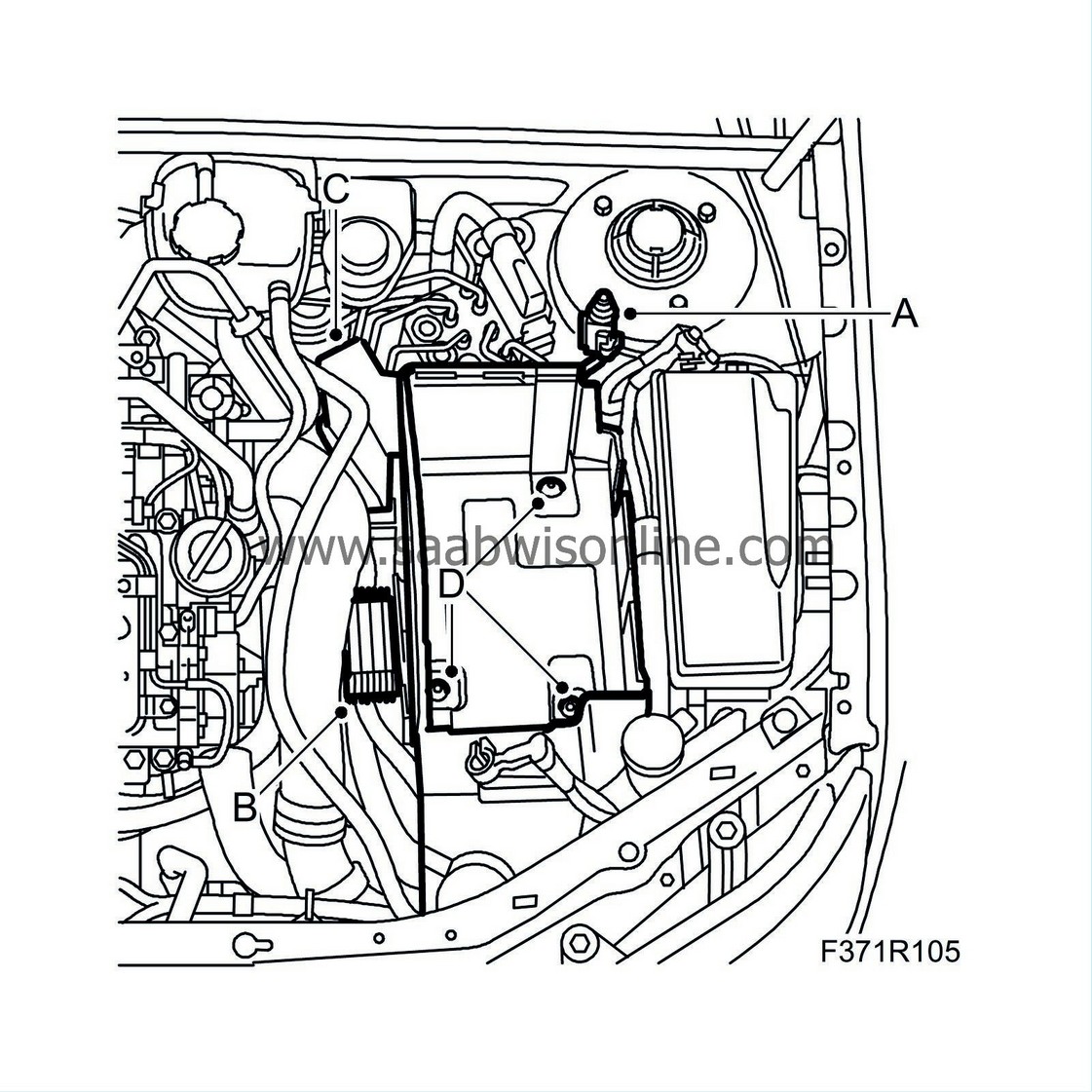
Remove the battery tray and components:
|
|
|
•
|
Remove the glow plug relay (B) and the fuse holder (C) from the battery tray.
|
|
|
•
|
Unplug the bonnet switch connector (A).
|
|
|
•
|
Remove the battery tray (D).
|
|
6.
|
Remove the bracket's nuts for connector H24-1 (black connector).
|
|
7.
|
Remove the wiper arms:
|
|
|
•
|
Remove the protective covers (A) from the wiper arms' retaining nuts.
|
|
|
•
|
Remove the wiper arms (B), use 85 80 144 Puller, windscreen wiper arm.
|
|
8.
|
Remove the cover and water barrier:
|
|
|
•
|
Remove the rear bonnet seal (A).
|
|
|
•
|
Remove the cover's clips (B).
|
|
|
•
|
Start to remove the cover (C) from the right-hand side: lift away the foam block and lift up the front edge of the cover so that the hook and the clips release, bend the corner tab aside. Continue with the left-hand side and undo the clips and the hook under the windscreen. Lift the cover away.
|
|
|
•
|
Remove the water barrier (D).
|
|
9.
|
Fold the clip (A) up from the filter holder and lift off the compartment filter (B).
|
|
10.
|
Lift up the wiring harness, which is placed under the filter holder. Dismantle the rubber grommet (A) and cut the cable tie (B). Remove the tape from around the rubber grommet.
|
|
11.
|
Route the new wheel sensor cable down along the structural member next to the damaged wheel sensor cable.
|
|
12.
|
Raise the car and angle the wheels to the right.
|
|
13.
|
Remove the damaged wheel sensor cable from the structural member and the wheel housing:
|
|
|
•
|
Remove the clip (A) from the structural member.
|
|
|
•
|
Remove the wheel sensor cable from the mountings (B).
|
|
|
•
|
Unplug the connector (C).
|
|
14.
|
Fit the wheel sensor cable to the structural member and the wheel housing:
|
|
|
•
|
Fit the wheel sensor cable to the mountings (B).
|
|
|
•
|
Clean the wheel sensor's connector (C) from any corrosion.
|
|
|
•
|
Plug in the connector (C).
|
|
|
•
|
Fit the clip (A) to the structural member.
|
|
15.
|
Prepared connection of the wheel sensor cable:
|
|
|
•
|
CV:
Remove the chassis reinforcement, front subframe in accordance with WIS - Suspension, wheels - Front suspension.
|
|
|
•
|
Remove the lower engine cover (A).
|
|
|
•
|
Remove the two outer screws (A) to the spoiler shield on the left-hand side & fold down the spoiler shield.
|
|
|
•
|
Lift out the bracket (B) and unplug the connector H24-1 (A). Move the connector up so that connection can take place from above.
|
|
17.
|
Cut off the damaged wheel sensor cable at the entry to the wiring harness coil on the right-hand side.
|
|
18.
|
Align and secure the wheel sensor cable to the right-hand side:
|
|
|
•
|
Route the wheel sensor cable up along the wiring harness, through the rubber grommet and on along the wiring harness.
|
|
|
•
|
Secure the wheel sensor cable (A) to the wiring harness. Use heat resistant fabric tape around the rubber grommet and fit the rubber grommet. Reposition the wiring harness under the filter holder.
|
|
19.
|
Align and secure the wheel sensor cable to the left-hand side:
|
|
|
•
|
Remove the rubber grommet (A) and cut the cable tie (B). Remove the tape around the rubber grommet.
|
|
|
•
|
Route the wheel sensor cable along the wiring harness, through the rubber grommet and on along the wiring harness.
|
|
|
•
|
Secure the wheel sensor cable (A) to the wiring harness. Tape heat resistant fabric tape around the rubber grommet and fit the rubber grommet.
|
|
20.
|
Connect the wheel sensor cable to connector H24-1:
|
|
|
•
|
Remove the seal in the connector.
|
|
|
•
|
Remove pin 5 and pin 6, use the extraction tool, 85 80 151.
|
|
|
•
|
Connect the wheel sensor cable's brown conductor to pin 5 and the black conductor to pin 6. Check that the sleeves are firmly locked and that they are at the same depth as other sleeves.
|
|
|
•
|
Fit the seal in the connector.
|
|
|
•
|
Move the connector (H24-1) down to its position.
|
|
22.
|
Fit connector H24-1 (A) to the bracket (B) and plug it in. Align the bracket onto the studs, in order to be able to fit the nuts from above.
|
|
23.
|
Refit the prepared connection of the wheel sensor cable:
|
|
|
•
|
Fold up the spoiler shield and fit the screws (A).
|
|
|
•
|
Fit the lower engine cover (A).
|
|
|
•
|
CV:
Fit the chassis reinforcement, front subframe in accordance with WIS - Suspension, wheels - Front suspension.
|
|
25.
|
Fit the nuts for the connector (H24-1) bracket.
|
|
26.
|
Secure the wheel sensor cable adjacent to the existing cable ties (A).
|
|
27.
|
Fit the compartment filter (B) and secure the clip (A).
|
|
28.
|
Fit the water barrier and cover:
|
|
|
•
|
Fit the water barrier (D).
|
|
|
•
|
Align the cover (C) and start to fit it from the left-hand side. Guide in the corner against the windscreen trim and the left-hand wiper spindle. Lift the foam block away and insert the hook under the windscreen. Align the cover against the right-hand wiper spindle. Fold down the corner tab so that it passes the hinge and bonnet. Align the corner tab under the windscreen trim. Insert the hook under the windscreen and press the cover down so that the clips engage.
|
|
|
•
|
Lift up the foam blocks and fit the clips (B).
|
|
|
•
|
Fit the rear bonnet seal (A).
|
|
29.
|
Fit the wiper arms:
|
|
|
•
|
Fit the wiper arms (B).
|
|
|
•
|
Fit the protective covers (A).
|
|
30.
|
Fit the battery tray and components:
|
|
|
•
|
Fit the battery tray (D).
|
|
|
•
|
Plug in the bonnet switch connector (A).
|
|
|
•
|
Fit the glow plug relay (B) and the fuse holder (C) to the battery tray.
|
|
31.
|
Align the battery and fit the battery's lock lug (A).
|
|
32.
|
Fit the battery's positive cable (A).
|
|
33.
|
Fit the battery's negative cable (B) and the battery cover (A).
|
|
34.
|
Carry out "Procedures after disconnecting the battery" in accordance with WIS - Electrical System - Wiring harness and components - Wiring harness.
|
|
35.
|
Clear any diagnostic trouble codes.
|
|
36.
|
Road test and check that no diagnostic trouble codes recur.
|
|
Marking the modification identity plate (not US/CA)
|
After carrying out the procedure, box B5 on the modification identity plate must be marked. From and including M04 the car's Warranty and Service Book contains the "Table of Modifications". Mark the box with the number "7" if the procedure was carried out by the importer or with the number "8" if carried out by the dealer.
|
Fitting the modification identity plate (not US/CA)
|
|
Note
|
|
A modification identity plate must only be fitted where local directives require the marking of the car.
|
Fit the modification identity plate in accordance with WIS
9-3 (9440) M04 - General - General - Technical data - Plates and labels
|
Warranty/Time Information
|
See separate information.


