Bush, front anti-roll bar, replacing, B207
|
|
Bush, front anti-roll bar, replacing, B207
|
|
Important
|
|
Scrupulous cleanliness must always be observed during all work with hydraulic components.
|
|
|
|
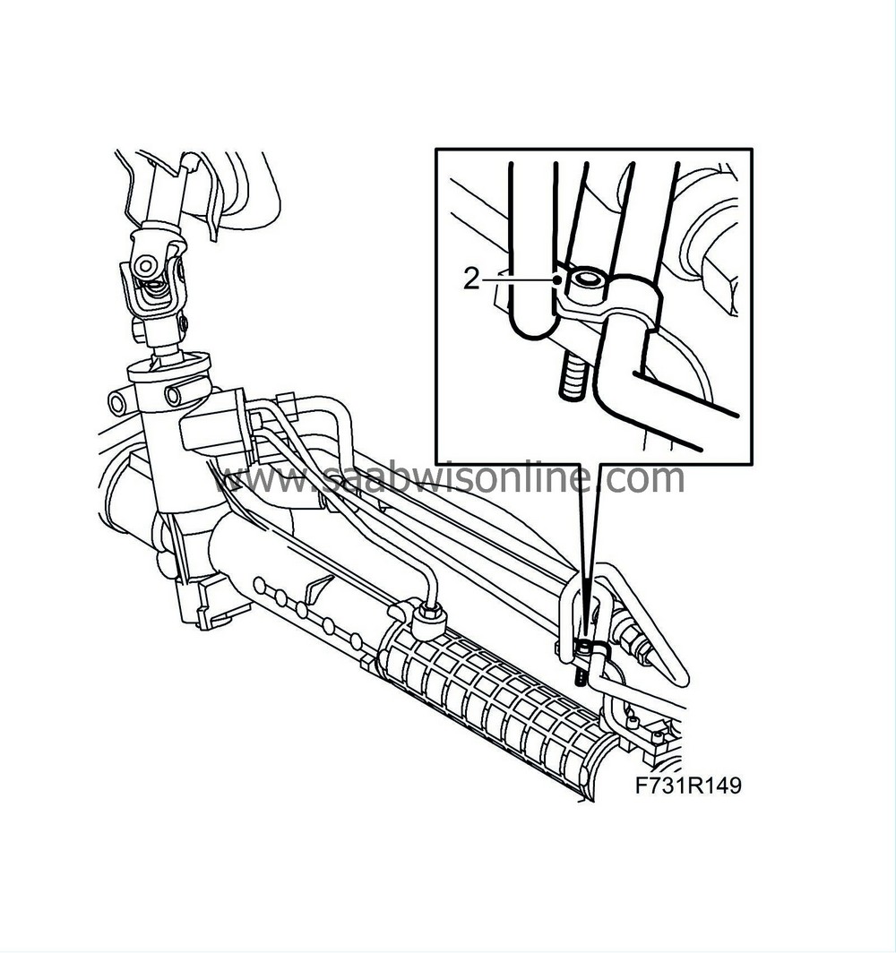
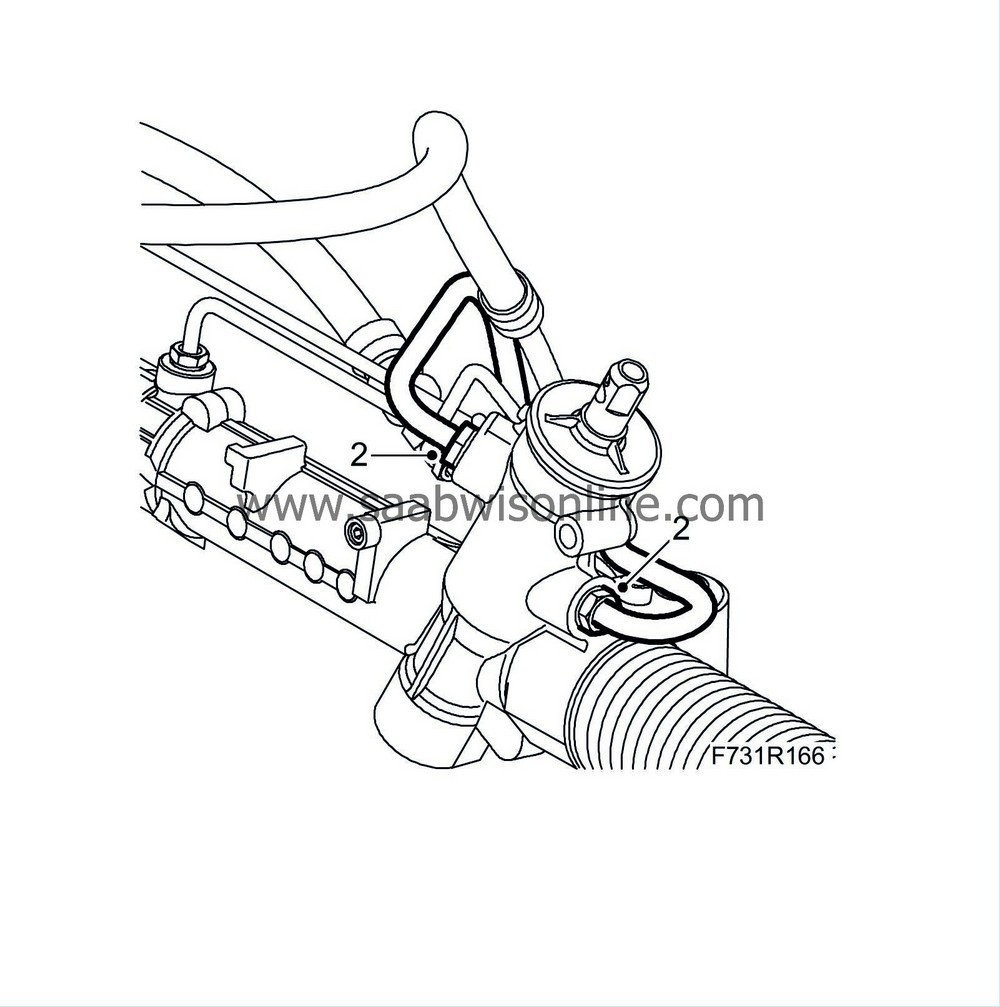
2.
|
Detach the pipes from the bracket on the top of the steering gear. Leave the bolt and clamp in place.
|
|
3.
|
Set the wheels and steering wheel to the straight-ahead position. Fix the steering wheel to the dashboard using woven tape or lock the steering wheel with the steering column lock.
|
|
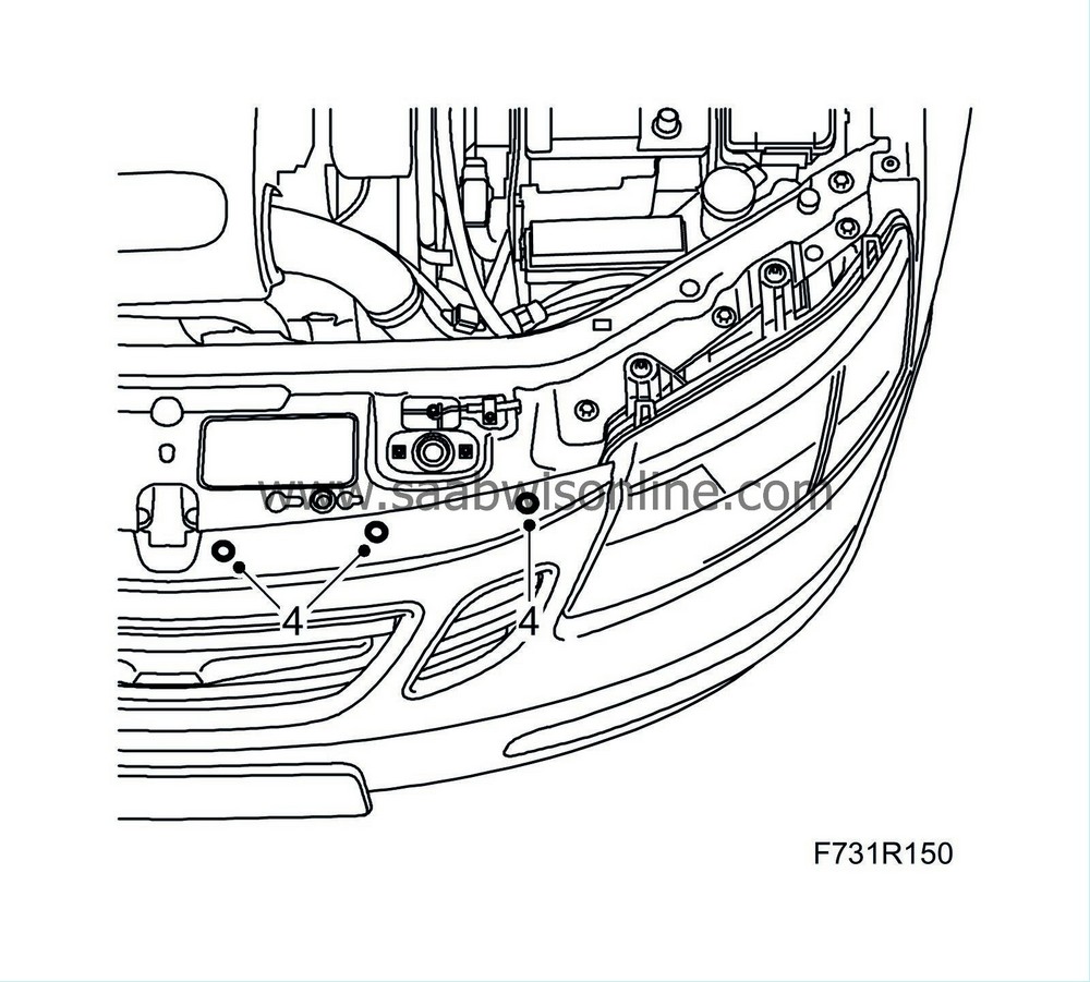
4.
|
Remove the upper bumper shell attachments.
|
|
5.
|
Hang two
83 95 212 Straps
in place over the radiator member and the radiator unit so that they are accessible from below.
|
|
7.
|
Remove the front wheels.
|
|
9.
|
Bind the radiator unit tightly with the straps.
|
|
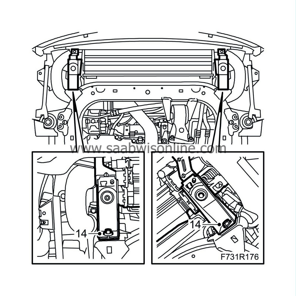
10.
|
Remove the radiator brackets from the subframe.
|
|
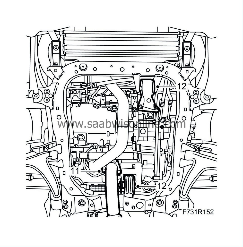
11.
|
Remove the exhaust system.
|
Important
|
|
The flexible bellow on the front section of the exhaust system must not be bent more than 5° from its neutral line. This means that if the front exhaust system is left hanging freely, it must not be bent more than by its own weight.
|
|
If the strain on the pipe is too great, its component parts will be permanently deformed. This can cause noise, leaks and eventually complete breakdown.
|
|
|
|
|
12.
|
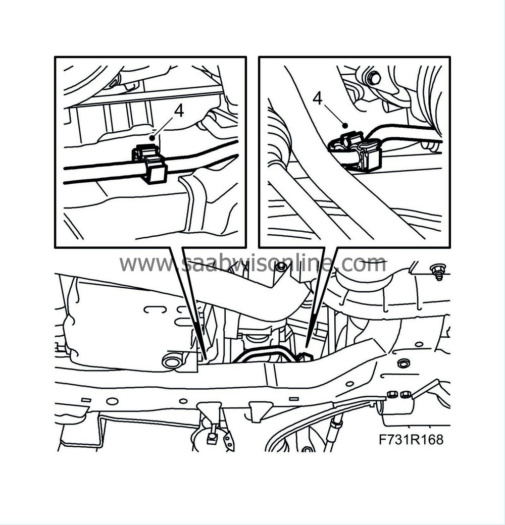
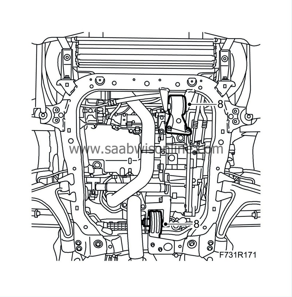
Remove the engine torque rod from the subframe.
|
|
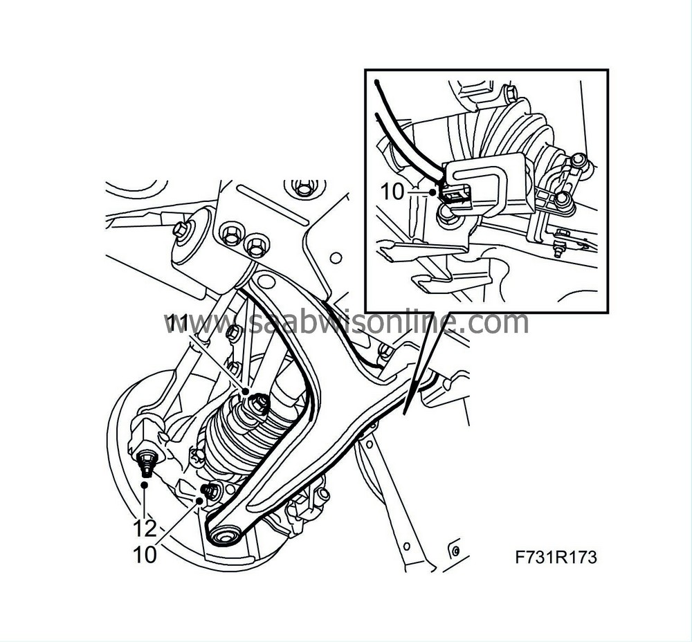
13.
|
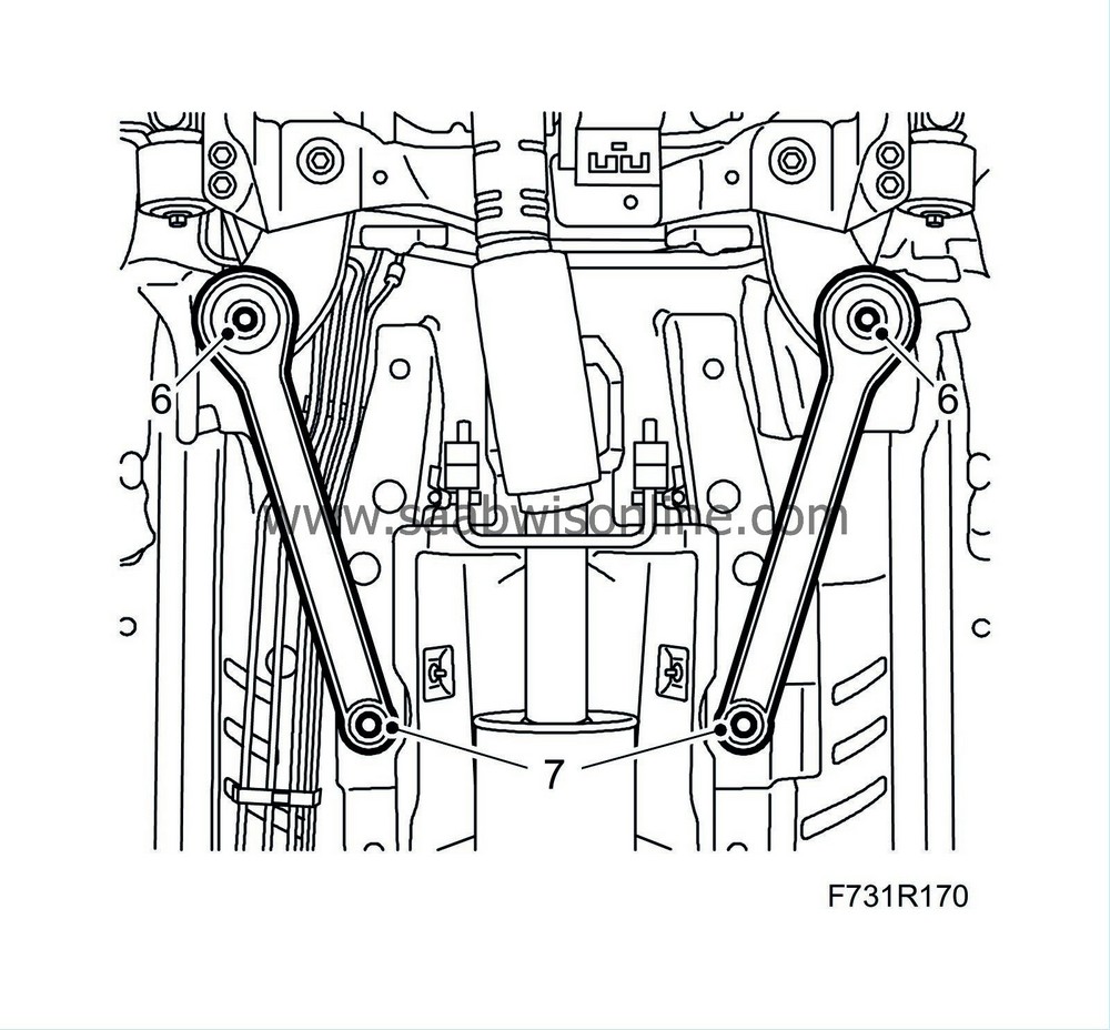
Remove the bolt and nut which attach the suspension arm to the steering swivel member on both sides.
Left-hand suspension arm and cars with xenon lights:
Remove the level sensor.

|
|
14.
|
Remove the nut holding the track rod ends to the steering swindle member on both sides. Remove the track rod using
87 91 287 Puller, 150 mm
.
|
|
15.
|
Remove the anti-roll bar links from the anti-roll bar. Counterhold with a thin 17 mm open wrench so that the ball joint does not rotate.
|
|
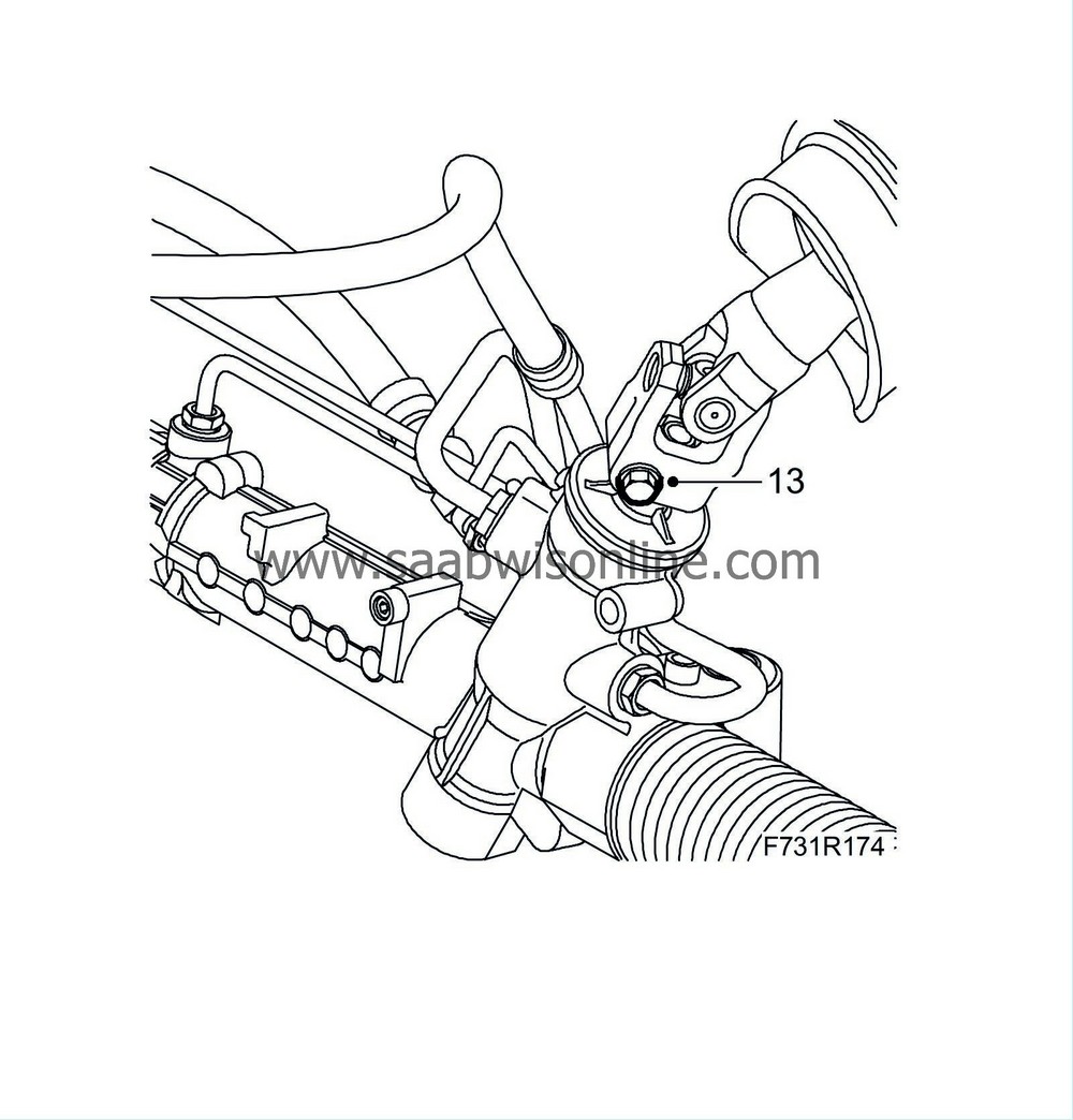
16.
|
Remove the steering shaft joint from the steering gear.
RHD:

LHD:

|
|
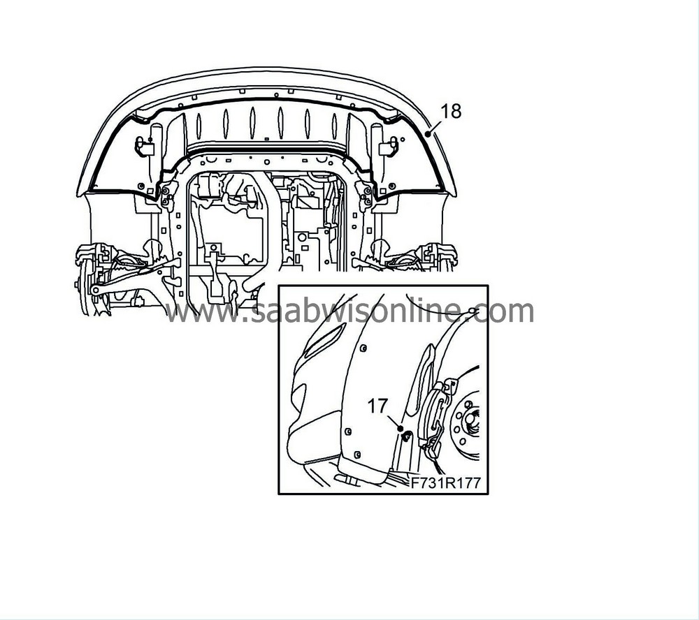
17.
|
Open the clips that secure the power steering pipe to the subframe.

|
|
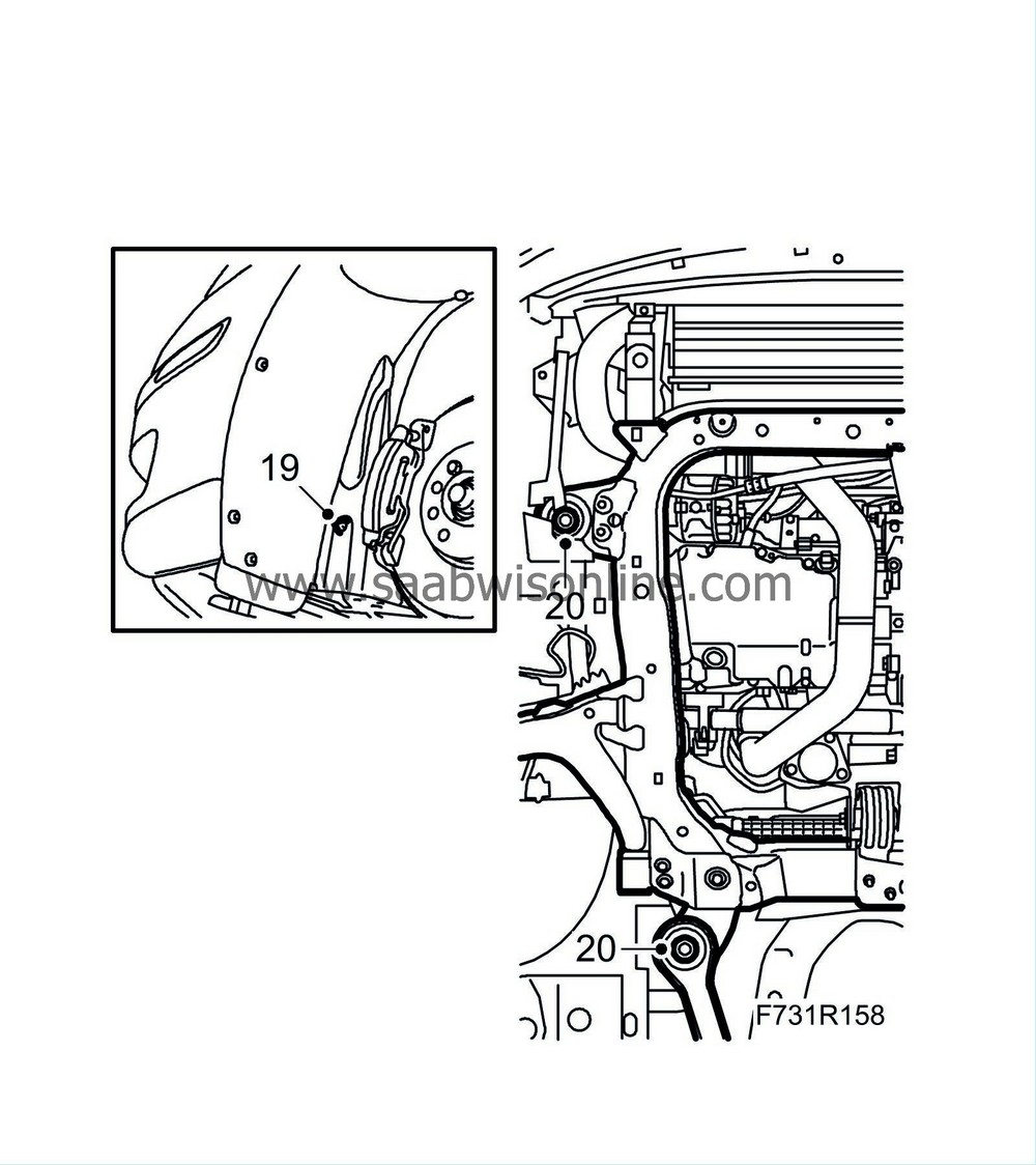
19.
|
Remove the front part of the wing liner and fold away slightly.
|
|
20.
|
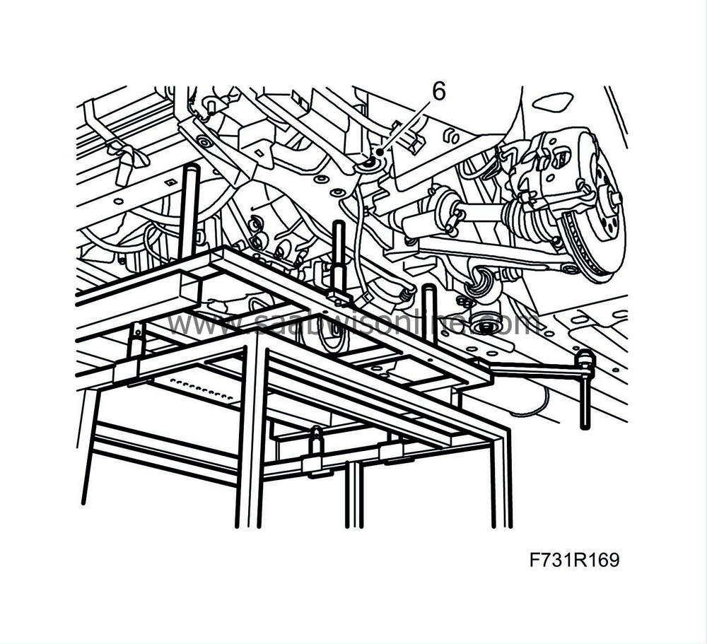
Remove the subframe bolts on both sides. Remove the stays from the body.
|
|
21.
|
Lower the subframe slightly.
|
|
22.
|
Pull out the suspension arms ball-and-socket joints from the steering swivel members.
|
|
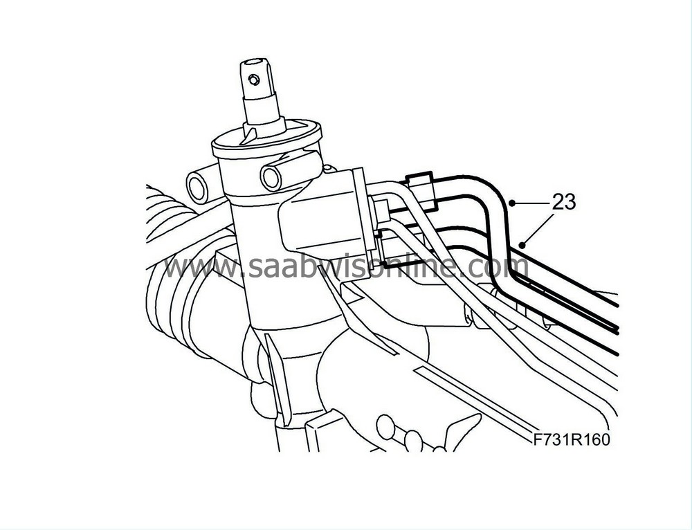
23.
|
Place a receptacle beneath the car. Detach the delivery line and return line from the steering gear. Plug the lines.
LHD:
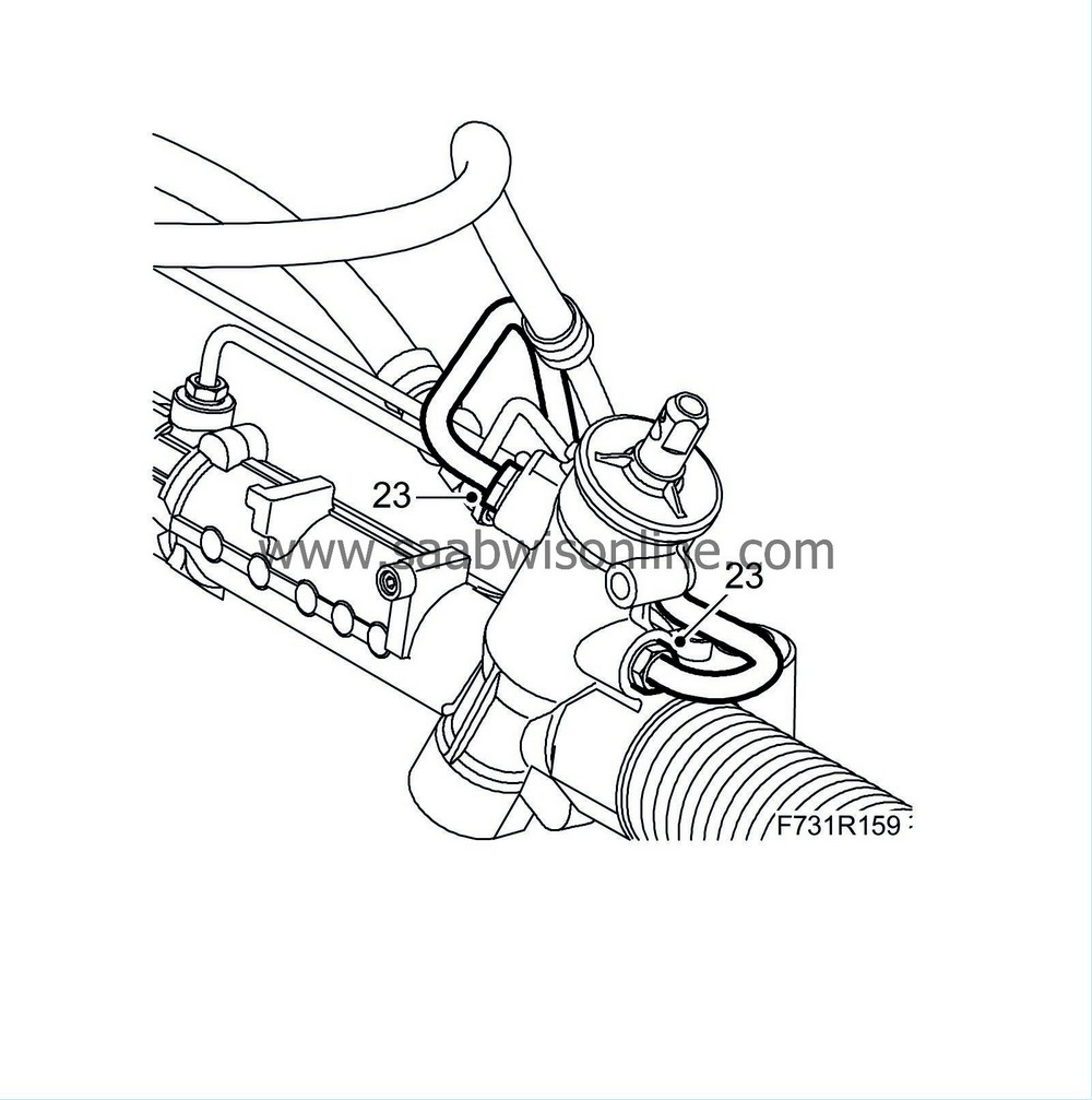
RHD:
|
|
25.
|
Replace the anti-roll bar bushes.
|
Important
|
|
Replace one side at a time.
|
|
|
|
Important
|
|
Do not lubricate the bushing or anti-roll bar when removing/installing.
|
|
|
|
|
|
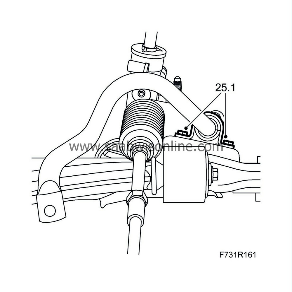
25.1.
|
Remove the bolts of the left anti-roll bar bush.
|
|
|
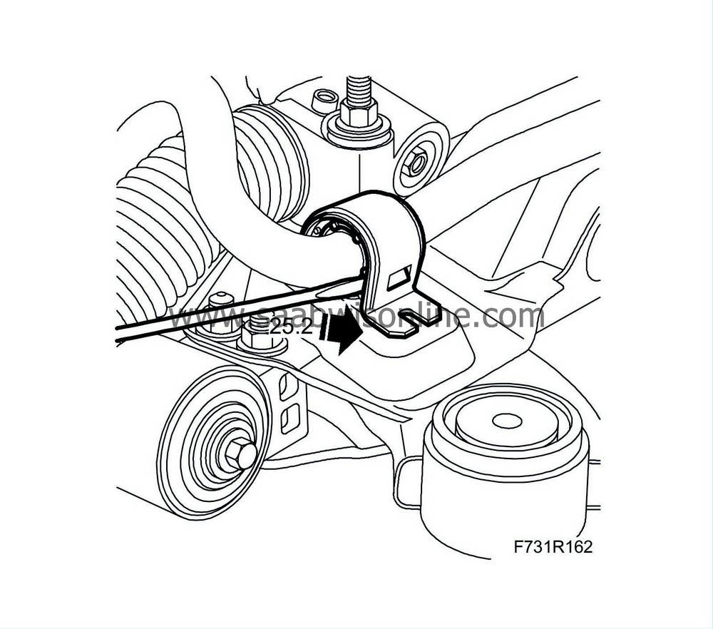
25.2.
|
Remove the cap from the bush.
|
|
|
25.3.
|
Remove the upper bush.
|
Note
|
|
The removed bush must not be reused. It must be replaced.
|
|
|
|
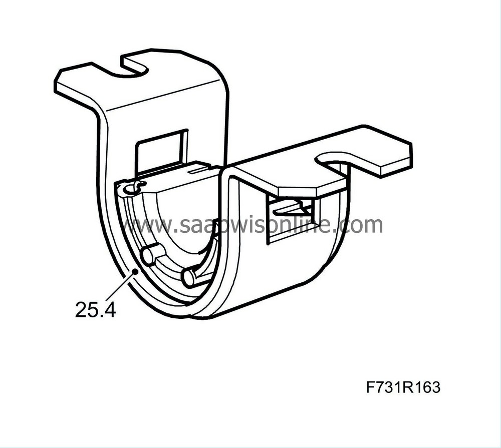
25.4.
|
Fit the upper bush, centred in the cap.
|
|
|
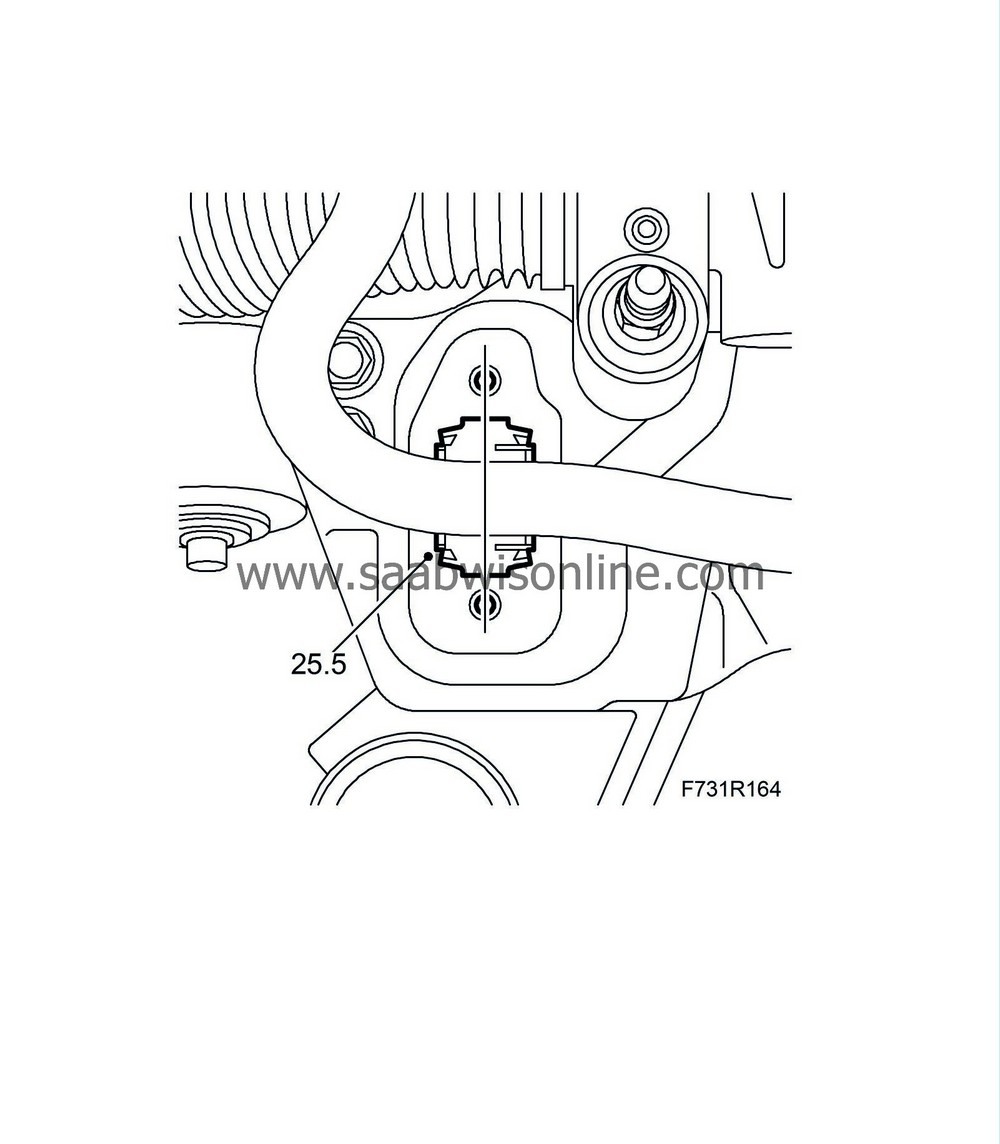
25.5.
|
Position the lower bush on the subframe, centred between the bolt holes.
|
|
|
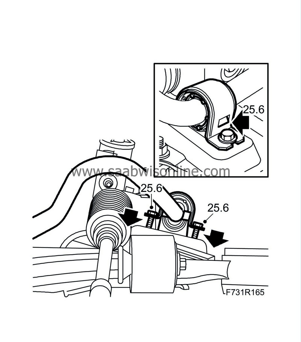
25.6.
|
Fit the cap with upper bush to the subframe. Tighten the bolts alternatingly until the lower bush's catches engage in the cap.
|
|
|
25.7.
|
Replace the temporary bolts (M8x30 mm) with the original bolts and tighten.
Tightening torque 18 Nm (13 lbf ft).
|
|
|
25.8.
|
Replace the right anti-roll bar bush following the same method.
|
|
1.
|
Lift the frame.
Fit the ball joints for the suspension arms in the steering swivel member.
|
|
2.
|
Attach the delivery line and return line to the steering gear. Fit new O-rings.
Tightening torque 28 Nm (21 lbf ft)
LHD:
RHD:
Make sure that the lines are correctly positioned against the bracket on the top of the steering gear.
|
Important
|
|
Make sure that the return line (line with the short nut) is connected to the lower of the two connections.
|
|
The steering gear will be destroyed if the lines are mixed up!
|
|
|

|
|
4.
|
Attach the power steering pipe to the plastic clips on the subframe.
|
|
5.
|
Lift the subframe so that the inner sections of the bushes are pressing against the body. Fit the front subframe bolts on both sides.
Tightening torque 75 Nm +135° (55 lbf ft +135°)
|
|
6.
|
Fit the stays and the rear subframe bolts on both sides. Enter the rear stay bolts before tightening the subframe bolts.
Tightening torque 75 Nm +135° (55 lbf ft +135°)
Lower and pull away the trolley lift.
|
|
7.
|
Tighten the rear stay bolts.
Tightening torque 90 Nm +45° (66 lbf ft +45°)
|
|
8.
|
Fit the engine torque rod to the subframe.
Tightening torque, rear torque rod 80 Nm (59 lbf ft)
Tightening torque, front torque rod 60 Nm +90° (44 lbf ft +90°)
|
|
10.
|
Fit the suspension arms to the steering swivel members.
 Warning
|
|
Press up the pin carefully.
|
|
The groove in the pin must be visible in the screw hole in the spindle housing.
|
|
If the rubber gaiter is pressed down, it will not seal properly to the swivel pin.
|
|
|
|
|
|
Tightening torque 50 Nm (37 lbf ft)
Left-hand suspension arm and cars with xenon lights:
Fit the level sensor.
|
|
11.
|
Install the anti-roll bar links to the anti-roll bar. Counterhold with a thin 17 mm open wrench so that the ball joint does not rotate.
Tightening torque 64 Nm (47 lbf ft)
|
|
12.
|
Fit the track rod ends to the steering swivel members.
Tightening torque 35 Nm (26 lbf ft)
|
|
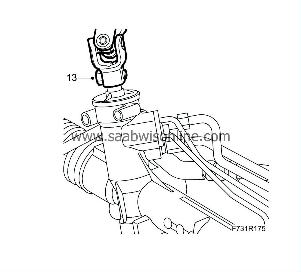
13.
|
Attach the steering shaft joint to the steering gear. Clean the threads and apply
Thread locking adhesive, Loctite 242
to the threads.
|
Warning
|
|
Check that the bolt fits into the groove on the pinion shaft.
|
|
|
|
|
|
LHD:
Tightening torque 30 Nm (22 lbf ft)
RHD:
Tightening torque 30 Nm (22 lbf ft)
|
|
14.
|
Fit the radiator brackets to the subframe.
Tightening torque 47 Nm (35 lbf ft)
|
Note
|
|
Check that the upper radiator unit support is placed correctly.
|
|
|
16.
|
Fit the exhaust system.
|
Important
|
|
Take care so as not to crack the flex bellows.
|
|
|
Tightening torque 25 Nm (18 lbf ft)
|
|
17.
|
Fit the front part of the wing liner on both sides of the car.
|
|
20.
|
Lower the car to the floor.
|
|
21.
|
Attach the pipes to the bracket on the top of the steering gear.

|
|
22.
|
Fit the upper bumper shell attachments.

|
|
24.
|
Remove the steering wheel fixing.
|
|
26.
|
Check the straight-ahead position of the steering wheel when driving on a level road. Adjust if necessary.
|


