|
No.
|
Name
Location
|
Illus.
|
|
|
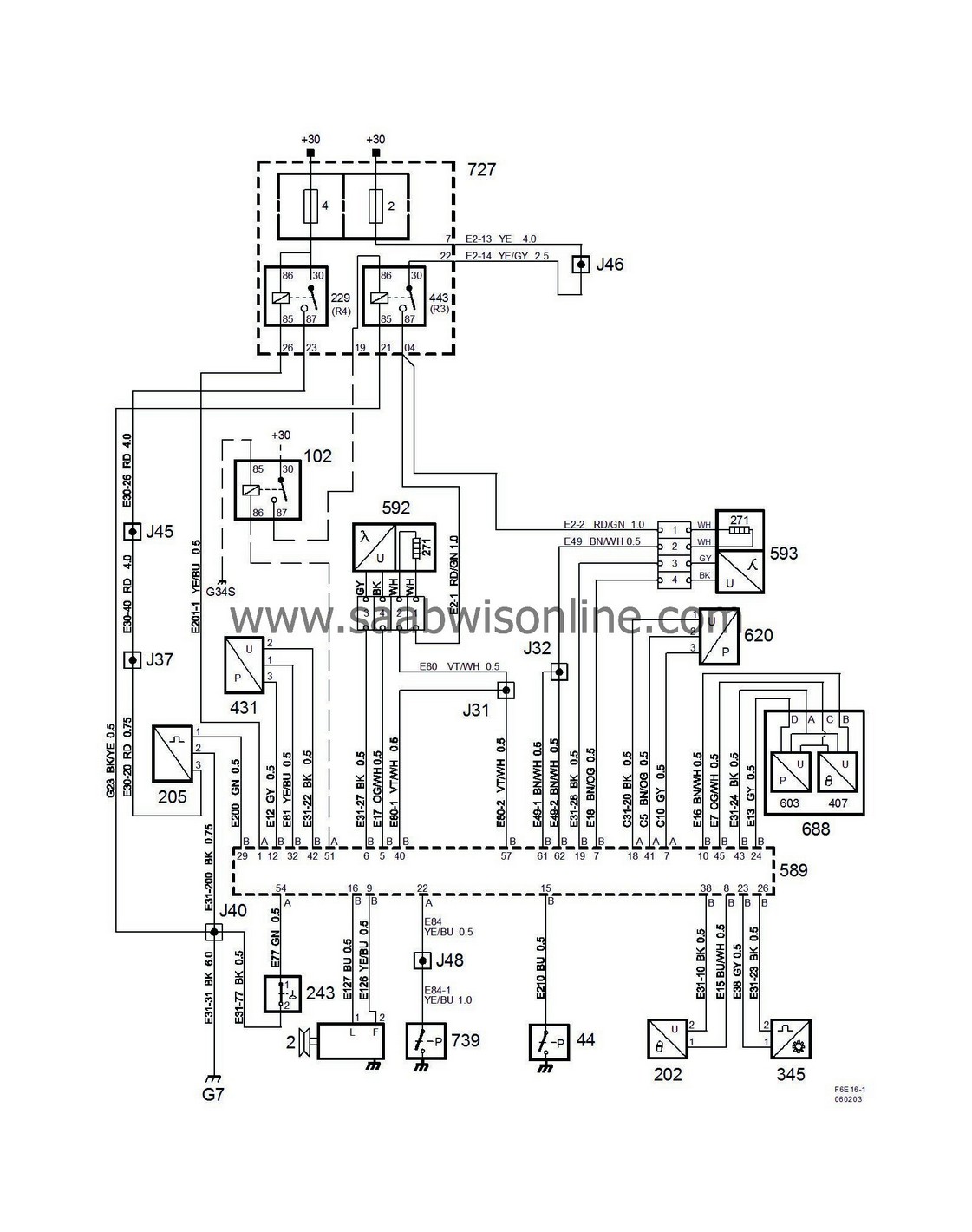
Components
|
|
|
2
|
Generator,
on the front long side of the engine (right)
|

|
|
44
|
Pressure switch, engine oil,
by the front edge of the oil filter
|

|
|
102
|
Fuel pump relay
below the right A-pillar
|

|
|
202
|
Coolant temperature sensor,
on the engine's top right front corner
|

|
|
205
|
Mass air flow sensor,
at right-hand MacPherson strut tower
|

|
|
229
|
Main relay, engine control system
in the main fuse box in front of battery
|

|
|
243
|
Engine oil level switch
at the bottom of front edge of the oil pan
|

|
|
271
|
Heated oxygen sensor element,
integrated in the oxygen sensor
|

|
|
345
|
Crankshaft position sensor,
above the starter motor
|

|
|
407
|
Intake air temperature sensor,
integrated in the intake air sensor 688 on the charge air pipe
|

|
|
431
|
Pressure sensor, intake manifold
next to the throttle body motor
|

|
|
443
|
Heated oxygen sensor relay
in the main fuse box in front of battery
|

|
|
589
|
Trionic engine control module, 4-cyl petrol,
on front of engine
|
A
B
|
|
592
|
Front heated oxygen sensor,
component:
before the catalytic converter
connector:
blue connector on the console between the power steering pump and the vacuum pump
|

|
|
593
|
Rear heated oxygen sensor,
component:
after the catalytic converter
connector:
brown connector on the bracket between the power steering pump and the vacuum pump
|

|
|
603
|
Pressure sensor, charge air,
integrated in the intake air sensor 688 on the charge air pipe
|

|
|
620
|
Pressure sensor, A/C,
on the air filter's top left front corner
|

|
|
688
|
Intake air sensor,
on the charge air pipe
|

|
|
727
|
Main fuse box , petrol engine,
in front of battery
|
2
4
|
|
739
|
Power steering fluid pressure sensor,
on the top of the servo pump
|

|
|
|
Crimp connections
|
|
|
J31
|
Approx. 20 mm from branching point engine control module's switch B towards its switch A
|

|
|
J32
|
Approx. 70 mm from branching point engine control module's switch B towards its switch A
|

|
|
J37
|
Approx. 260 mm from branching of crankshaft sensor towards the engine control module
|

|
|
J40
|
Approx. 190 mm from branching point crankshaft sensor towards the engine control module
|

|
|
J45
|
Approx. 250 mm from branching point connector H24-2 towards the engine control module
|

|
|
J46
|
Approx. 130 mm from connector H24-2
|

|
|
J48
|
Approx. 80 mm from branching point ignition coil with integrated power amplifier for cylinder 4 towards the engine control module
|

|
|
|
Grounding points
|
|
|
G7
|
on the engine control module's top right attachment lug
|

|
|
G34S
|
On the floor below the left A-pillar
|

|


