Crankshaft and pistons, to fit
|
|
Crankshaft and pistons, to fit
|
|
1.
|
Wash the dismantled parts and blow clean oilways with compressed air.
|
|
2.
|
Clean the bolt holes in the cylinder block.
|
|
3.
|
Clean away any gasket remains from the cylinder head and cylinder block sealing surfaces.
|
|
4.
|
Check for cracks or scores in the cylinder block.
|
|
5.
|
Check that cylinder block flatness is within recommended limits. If not, the block must be refaced.
|
Permitted flatness fault
|
mm
|
< 0.1
|
|
|
6.
|
Measure the diameter of the cylinder liners to see whether they are within the limits below.
|
Cylinder bore
|
mm
|
Category B
|
82.010 - 82.020
|
|
|
mm
|
Category C
|
82.020 - 82.030
|
|
|
mm
|
Class A
|
82.000 - 82.010
|
|
|
7.
|
Check that conicity is within the limits in the table.
|
Permitted conicity
|
mm
|
0.005
|
|
|
8.
|
Check that ovality is within recommended limits.
|
Permitted ovality, mm
|
mm
|
0.05
|
|
|
9.
|
If the values exceed those recommended, the cylinder barrel must be bored to the next oversize.
|
Note
|
|
If it is necessary to bore one cylinder then they must all be bored.
|
|
Cylinder liner oversize
|
mm
|
0.1
|
|
|
10.
|
Fit the main bearing caps temporarily.
|
Note
|
|
The bearing caps must be mounted in ascending numerical order from 0 to 4 starting at the front of the engine.
|
|
|
11.
|
Tighten the bearing cap bolts. Use a protractor for angle tightening.
Tightening torque 25 Nm + 100° (18 lbf ft +100°).
|
|
12.
|
Check that the bearing seat diameters are within recommended limits.
|
Crankshaft bearing seats, diameter
|
mm
|
63.705 - 63.718
|
|
|
13.
|
Check that the crankshaft oilways are free from contaminants.
|
|
14.
|
Check that the main bearing journal diameter is within recommended limits:
|
Main bearing journal diameter
|
mm
|
Category B
|
59.988 - 59.994
|
|
|
mm
|
Category C
|
59.982 - 59.988
|
|
|
mm
|
Class A
|
59.994 - 60.000
|
|
|
15.
|
If the main bearing journal diameters are outside recommended limits, they must be ground down to the next undersize.
|
Main bearing journal, recommended undersize
|
mm
|
0.127
|
|
Note
|
|
Undersizes of main bearings that exceed the above recommendations will have a negative effect on the structural strength of the crankshaft. If regrinding requires an undersize of more than 0.127 mm, the crankshaft must be changed even though there are bearing shells available for undersizes greater than 0.127 mm.
|
|
|
16.
|
Check that the big-end bearing journal diameters are within recommended limits.
|
Big-end bearing journal diameter
|
mm
|
Category B
|
50.793 - 50.799
|
|
|
mm
|
Category C
|
50.787 - 50.793
|
|
|
mm
|
Class A
|
50.799 - 50.805
|
|
|
17.
|
If the big end bearing journal diameters are outside recommended limits, they must be ground down to the next undersize.
|
Big-end bearing journal, recommended undersize
|
mm
|
0.127
|
|
Note
|
|
Undersizes of big end bearings that exceed the above recommendations will have a negative effect on the structural strength of the crankshaft. If regrinding requires an undersize of more than 0.127 mm, the crankshaft must be changed even though there are bearing shells available for undersizes greater than 0.127 mm.
|
|
|
18.
|
Check the crankshaft bearings. They must be changed if there are any signs of scoring or other damage. Note that if the crankshaft has been reground, fit new oversize bearing shells to restore original tolerances.
|
|
19.
|
Remove the circlips and press out the gudgeon pin.
|
|
20.
|
Check the inside diameter of the connecting rod piston end. If it is outside recommended limits, change the worn bearing bushing.
|
Inside diameter of bearing bushing, piston end
|
mm
|
26.006 - 26.014
|
|
|
21.
|
Check that the piston bearing diameters are within recommended limits. If not, change the piston complete with piston rings gudgeon pin and bushings.
|
Inside diameter of piston bearing
|
mm
|
25.999 - 26.004
|
|
|
22.
|
Check that gudgeon pin outside diameters are within recommended limits. If not, change gudgeon pins.
|
Outside diameter, gudgeon pins
|
mm
|
25.982 - 25.987
|
|
|
23.
|
Position the piston rings and oil scraper rings individually in the cylinder liners and measure the ring gaps. If they are not within recommended dimensions, change the piston rings and oil scraper rings respectively.
|
Piston ring gap
|
mm
|
0.20 - 0.35
|
|
Oil scraper ring gap
|
mm
|
0.25 - 0.50
|
|
|
24.
|
Check that piston outside diameters are within recommended limits. If not, change pistons complete with rings and gudgeon pin.
|
Piston outside diameter, mm
|
mm
|
Category B
|
81.930 - 81.940
|
|
|
mm
|
Category A
|
81.920 - 81.930
|
|
|
mm
|
Category C
|
81.940 - 81.950
|
|
Note
|
|
Measurement is to be done at right angles to the gudgeon pin, 9 mm from the bottom of the piston.
|
|
|
25.
|
Check that the play between the compression rings and the groove in the piston is within recommended limits.
|
Compression ring play in groove
|
mm
|
0.050 -0.090
|
|
|
26.
|
Check that the play between the oil scraper ring and the groove in the piston is within recommended limits.
|
Oil scraper ring play in groove
|
mm
|
0.030 - 0.070
|
|
|
27.
|
Fit the crankshaft big end bearing caps and check that the dimensions are within recommended limits.
Tightening torque 25 Nm +60° (18 lbf ft +60°).
|
Inside diameter of crankshaft big end bearing
|
mm
|
53.897 - 53.909
|
If the measurement is outside recommended limits, change the connecting rods.
|
|
28.
|
Fit the gudgeon pin, circlips and piston rings. The recess for the piston cooling nozzles must be turned in the same direction as the marks on the connecting rods.
|
|
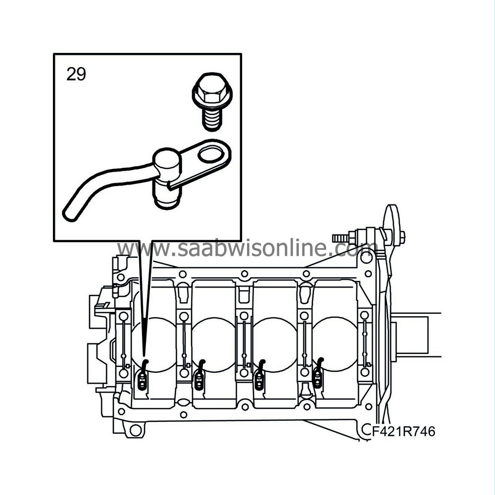
29.
|
Fit the piston cooling nozzles.
|
|
30.
|
Oil mating surfaces with engine oil.
|
|
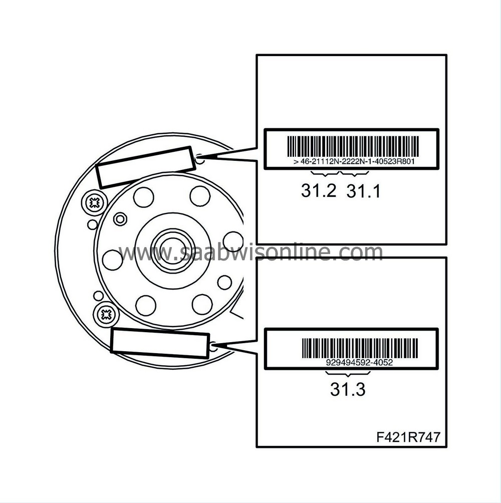
31.
|
The code number stamped on the slotted ring and the colour code (if present) next to the crankshaft journal will be needed to be able to choose the right bearing half. The following example shows how to obtain the crankshaft journal classification.
|
|
|
31.1.
|
Identifying big end bearing journal classification: the number on the left refers to the first bearing on the timing gear side. The letter "N" at the end has no significance on 4-cylinder engines.
|
|
|
31.2.
|
Identifying main bearing journal classification: the first number on the left-hand side refers to the first big end bearing on the timing gear side. The letter "N" at the end has no significance on 4-cylinder engines.
|
|
|
31.3.
|
The number series (if present) with groups of two numbers indicate the dimensions (in thousandths) of the main bearing journals. The first two numbers on the left refer to the first big end bearing on the timing gear side.
|
Note
|
|
Only the number in the marking above are used. Other numerical codes on the flywheel are not to be used.
|
|
|
32.
|
The crankshaft bearings are identified as follows:
|
|
|
32.1.
|
To identify the main bearing journal classification, see the numerical code referred to in 31.2. If the numbers are the same as the example 11111N, this means that all five bearings are grade A (red marking).
|
|
|
32.2.
|
One way of identifying the bearing grade is to read the reference number in 31.3 (if present). In the illustrated example, the number 94 (the first on the left) means that the first bearing dimension on the timing gear side is 52.994 mm, indicating grade A (red marking). The same method applies to the other groups of two numbers (97-95-95-94).
|
|
|
32.3.
|
The main bearing is identified as follows:
|
Degree
|
Diameter
|
Colour marking
|
Code number
|
|
A (normal)
|
52.994 53.000
|
Red
|
1 (94 00)*
|
|
B (normal)
|
59.988 59.994
|
Blue
|
2 (88 94)*
|
|
C (normal)
|
52.982 52.988
|
Yellow
|
3 (82 88)*
|
|
D (0.127 mm undersize)
|
59.867 59.873
|
brown
|
6 (67 73)*
|
|
E (0.127 mm undersize)
|
59.861 59.863
|
Green
|
7 (61 67)*
|
|
F (0.127 mm undersize)
|
52.855 52.861
|
Black
|
8 (55 61)*
|
* The last two numbers indicate the final two thousandths of the dimensions
|
|
|
32.4.
|
If a crankshaft where the maximum bearing undersize due to regrinding has become 0.127 mm is being used, the grade should be chosen after measuring the bearing diameters as shown in the table above. After determining the grade and colour of each new or reground crankshaft bearing, it will be necessary to order the corresponding bearing halves with colour coding according to the table. The recommendations given in the table are to attain optimum bearing play for best function. It is also important to be aware that the clearance between the crankshaft and the bearing halves determined in the above measurements should be between the following values: min 0.011 mm and max 0.071 mm. This can be measured as a final check using Plastigauge.
|
|
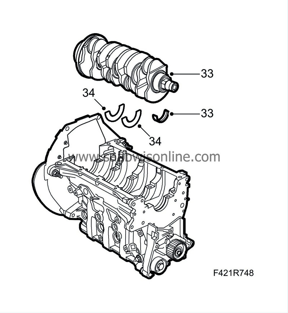
33.
|
Place the upper bearing halves in their seats with the holes towards the oilways. Lubricate with engine oil. Position the crankshaft.
|
Note
|
|
The bearing caps are numbered in ascending order from 0 to 4 starting at the timing gear end of the engine.
|
|
|
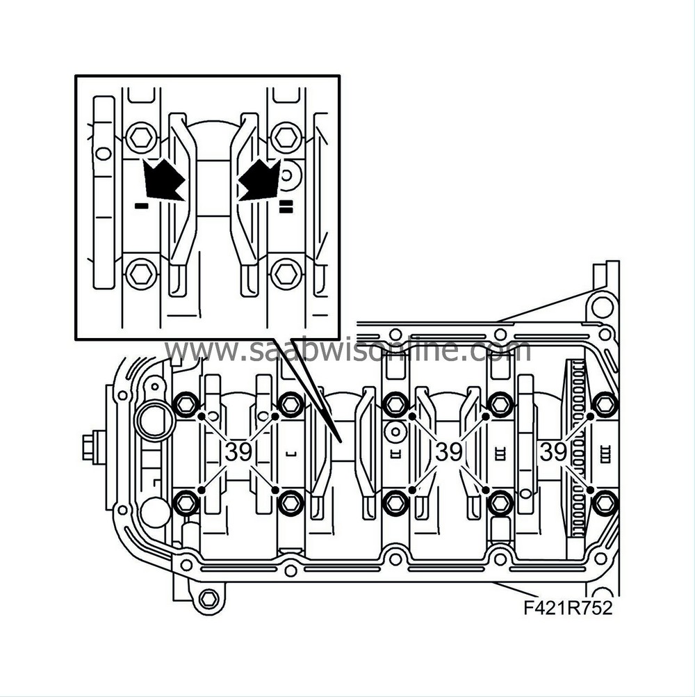
34.
|
Fit the thrust bearings into the third main bearing housing. Choose the correct dimensions with regard to crankshaft end float. The grooves on the bearings must be turned towards the crankshaft bearing surface.
|
|
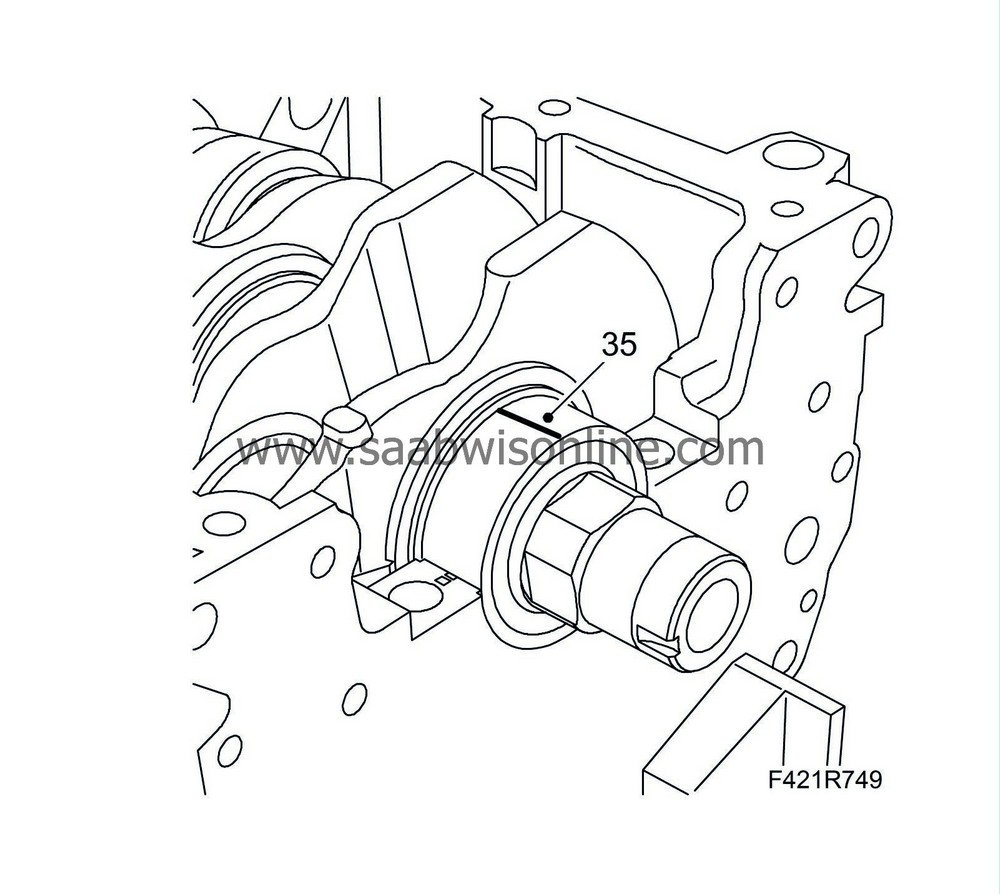
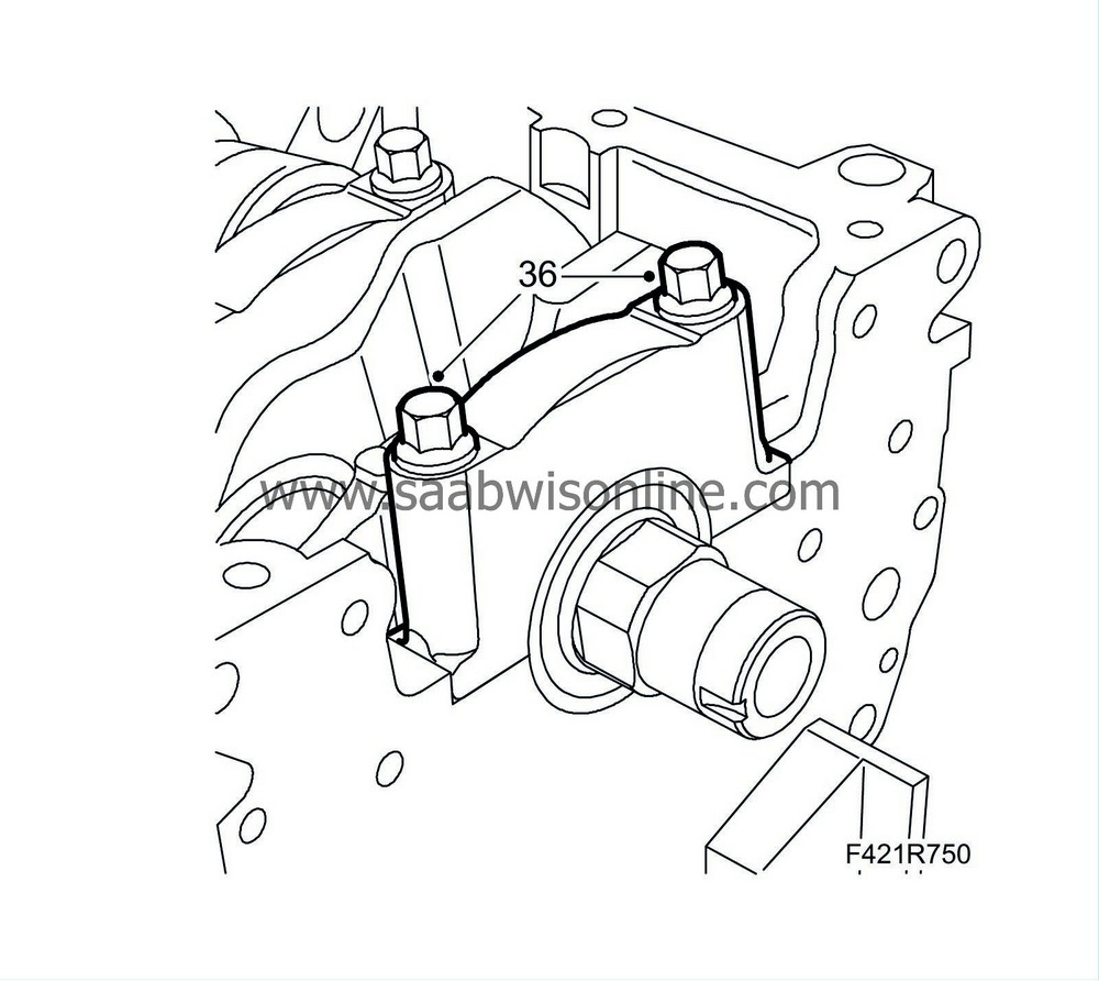
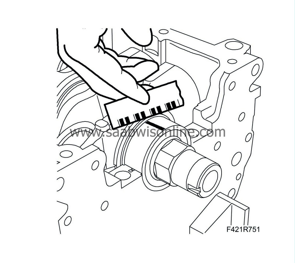
35.
|
Use Plastigauge to measure the bearing play as illustrated.
|
Note
|
|
Check one main bearing journal at a time without rotating the crankshaft.
|
|
|
36.
|
Fit the crankshaft main bearing caps complete with bearing shells.
Tightening torque 25 Nm +100° (18 lbf ft +100°)
|
|
37.
|
Remove the newly mounted main bearing caps and measure the play using the calibrated wire.
|
Play between big end bearings and crankshaft journals
|
mm
|
0.011 - 0.071
|
If the measurements are not within the recommended interval, change bearing shells to suitable category and dimension.
|
|
38.
|
Continue measuring all the bearings, one at a time, without rotating the crankshaft.
|
|
39.
|
After measuring, lubricate the bearings and refit the main bearing caps.
Tightening torque 25 Nm +100° (18 lbf ft +100°).
|
|
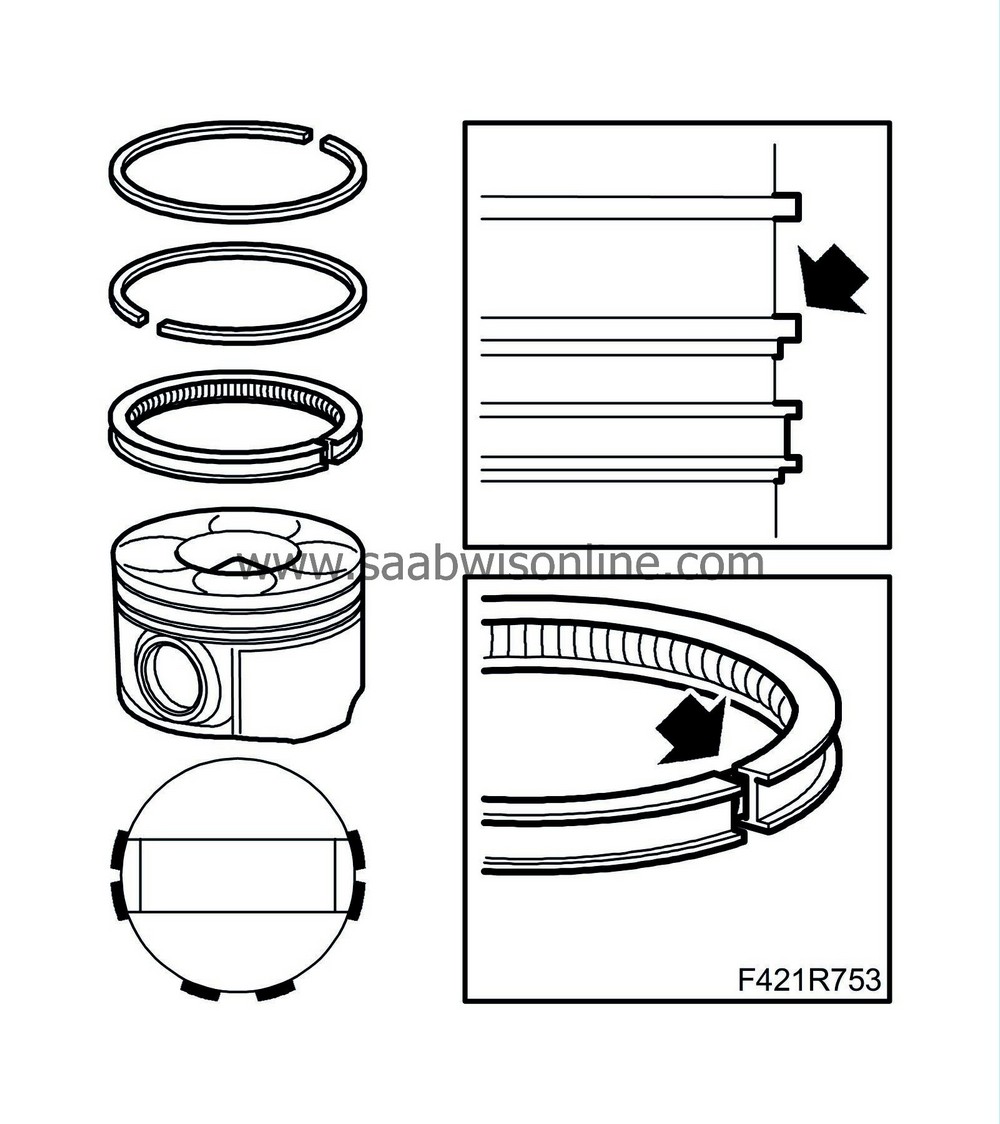
40.
|
Place the piston rings as illustrated. The piston ring gaps must be positioned at 120° to each other.
|
|
41.
|
Lubricate the cylinder bore and piston with engine oil.
|
|
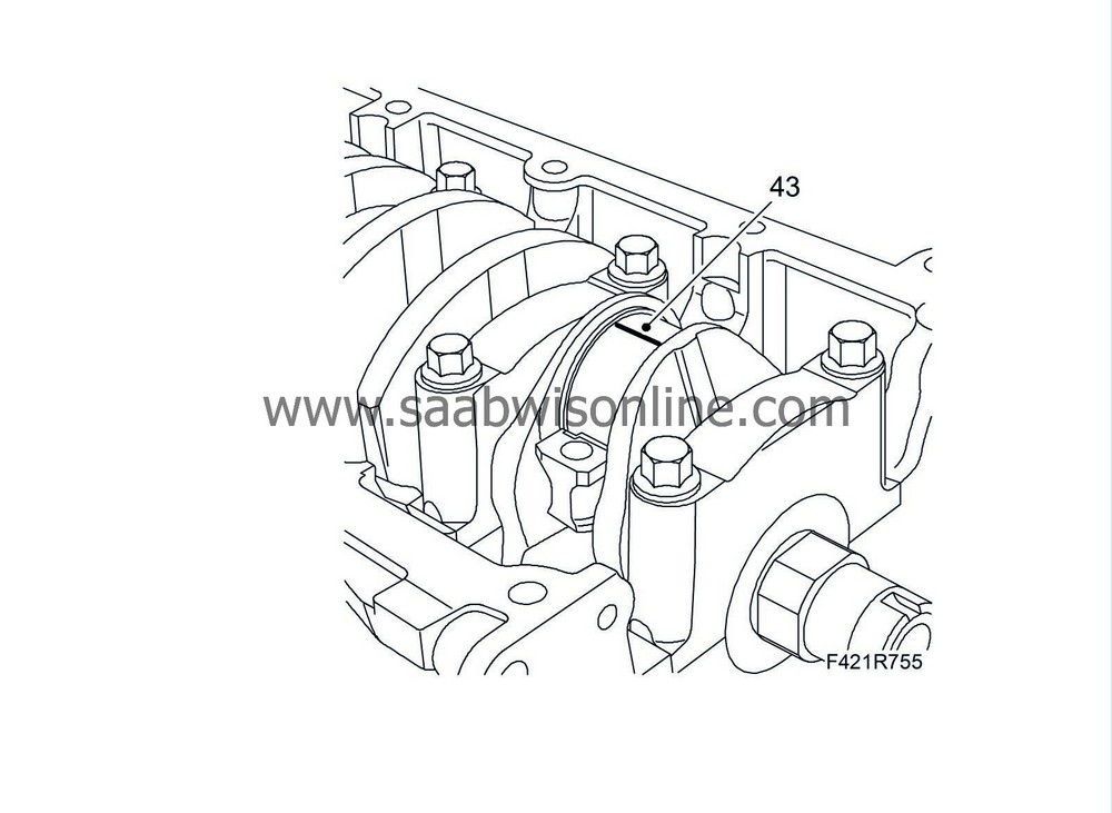
43.
|
Use Plastigauge to measure the bearing play as illustrated.
|
|
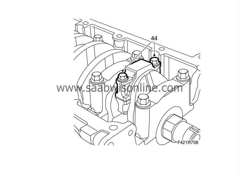
44.
|
Fit the bearing caps with the marks facing the marks on the connecting rods.
Tightening torque 25 Nm +60° (18 lbf ft +60°)
|
|
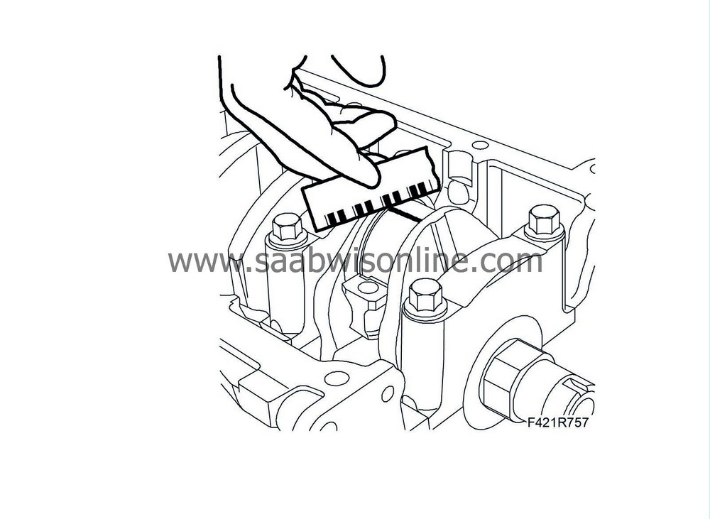
45.
|
Remove the newly mounted big-end bearing caps and measure the play using the calibrated wire.
|
Play between big-end bearing and big-end bearing journal
|
mm
|
0.016 - 0.070
|
If the measurement does not agree with the recommended one, change the bearing shells.
|
|
46.
|
Refit the big-end bearing gaps complete with bearing halves for cylinders 1 and 4. Lubricate with engine oil.
Tightening torque 25 Nm +60° (18 lbf ft +60°).

|
|
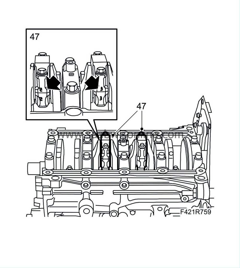
47.
|
Turn the crankshaft a 1/2 turn and perform steps 40-46 on cylinders 2 and 3.
|
|
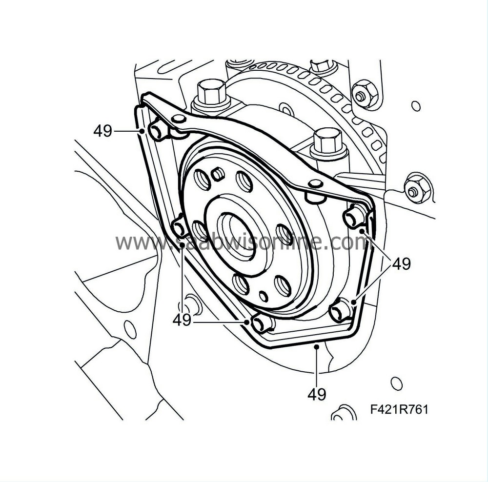
49.
|
Fit the bolts.
Tightening torque 9 Nm (6 lbf ft).
|
|
50.
|
Clean the oil pump threads and sealing surfaces and remove the seal.
|
|
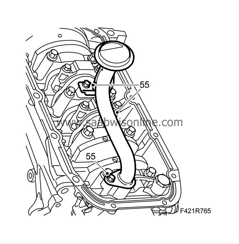
55.
|
Fit the oil intake pipe.
|
|
56.
|
Remove the oil sump baffle plate and wash the oil sump. Clean the sealing surfaces on the engine block and sump. Remove any contaminants in the oil sump. Fit the oil sump baffle plate.
|
|
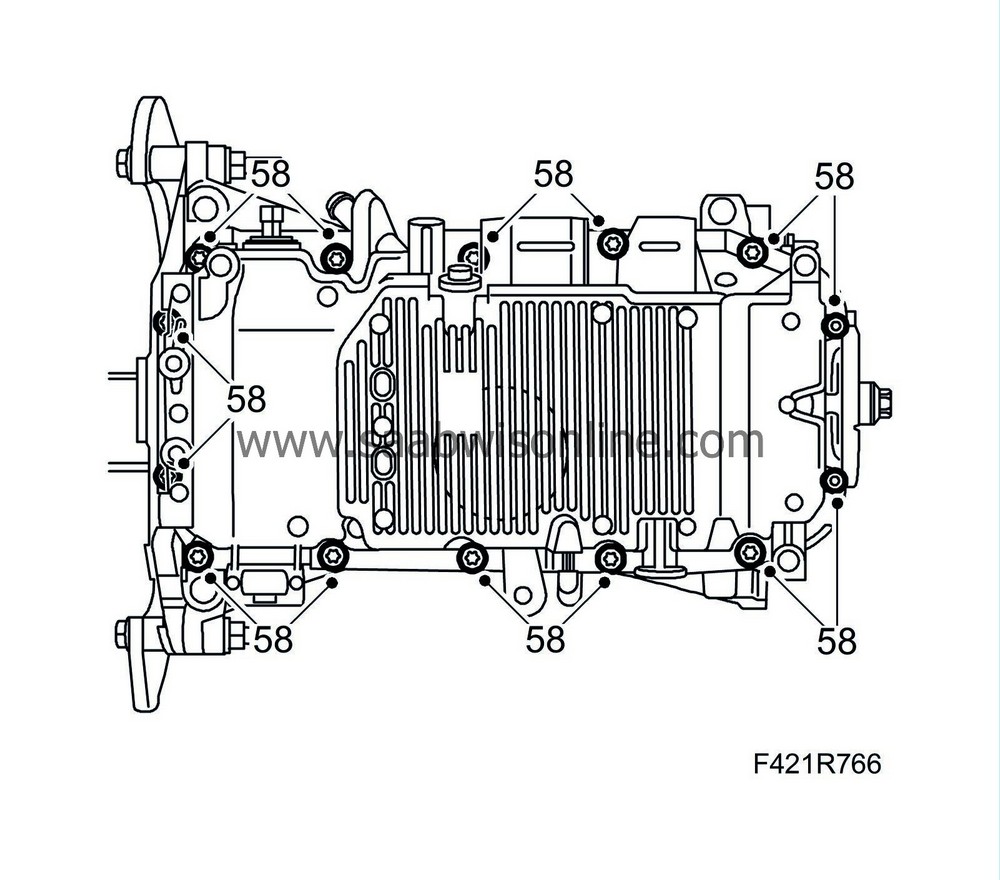
58.
|
Fit the oil sump carefully so that the sealing compound is not disturbed.
Tightening torque, M6 bolts, 9 Nm (7 lbf ft).
Tightening torque, M8 bolts, 25 Nm (18 lbf ft).
|
|
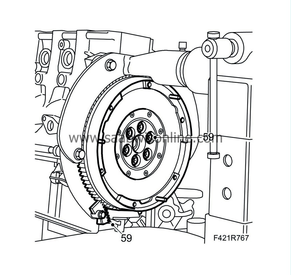
59.
|
Fit the flywheel or driver plate with new bolts. Use
Thread locking adhesive, Loctite 270
on the bolts. Fit
83 92 987 Flywheel locking attachment
into the threaded hole in the oil sump to lock the flywheel. Tighten the bolts alternately.
Tightening torque, 160 Nm (118 lbf ft)
|
Important
|
|
The clutch plate and pressure plate have been matched with each other and must therefore be changed together.
|
|
|
|
|
60.
|
Man
: Place the clutch disc and pressure plate on the flywheel and screw in the bolts loosely. Apply
Thread locking adhesive, Loctite 242
to the threads. The convex side of the clutch disc should be turned towards the gearbox.
|
|
62.
|
Remove the flywheel locking attachment and centring tool.
|
|
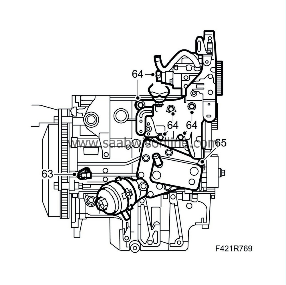
63.
|
Fit the crankshaft position sensor.
|
|
64.
|
Fit the bracket to the fuel pump.
Tightening torque 25 Nm (18 lbf ft)
|
|
65.
|
Fit the oil cooler with new seals greased with Vaseline.
Tightening torque 50 Nm (37 lbf ft)
|
|
66.
|
Set piston no. 1 to TDC.
|
Important
|
|
Do not confuse the engine block guide sleeves with the camshaft guide sleeves.
|
|
|
|
|
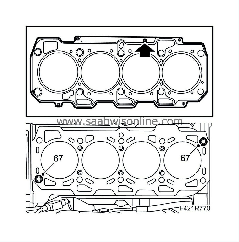
67.
|
Place the guide sleeves on the engine block.
|
|
68.
|
Fit a new gasket with the same thickness as the old one. Carry out
Measuring piston height
if the connecting rods or pistons have been changed.
|
|
69.
|
Position the cylinder head on the cylinder block.
|
|
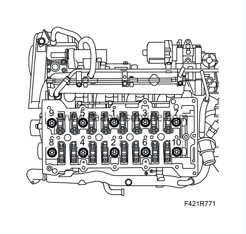
70.
|
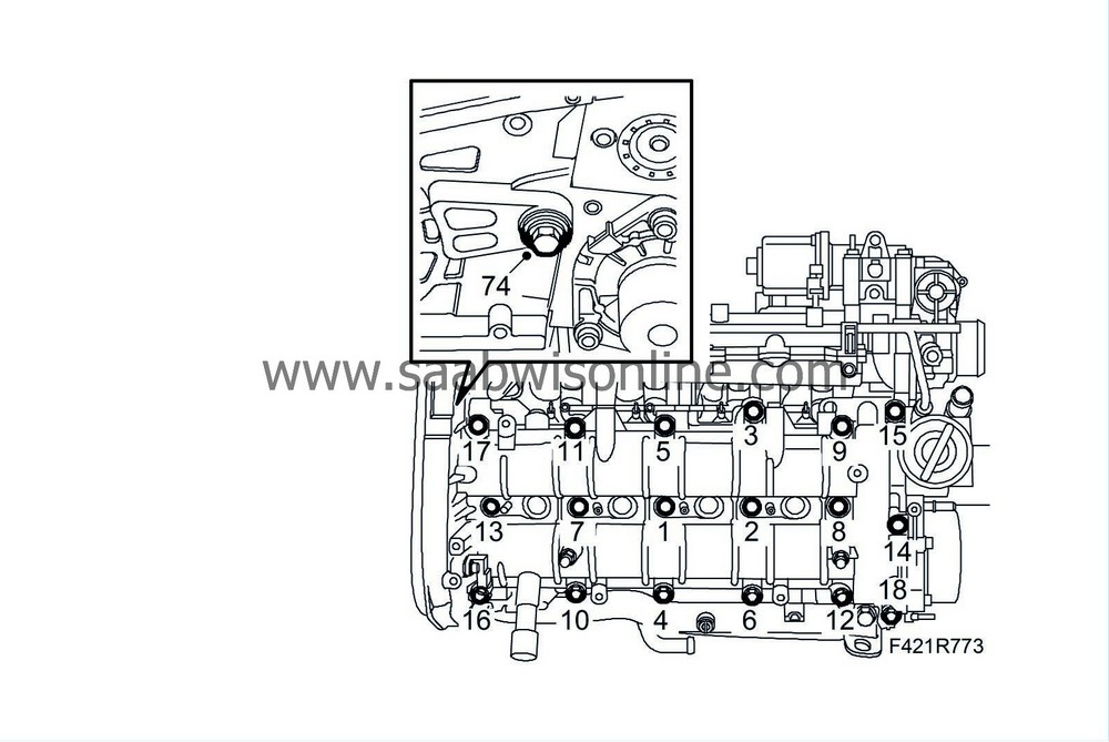
Tighten the cylinder head bolts in the illustrated order.
Tightening torque step I, 65 Nm (48 lbf ft)
Stage II +90°
Stage III +90°
Stage IV +90°
|
|
71.
|
Clean the cylinder head and camshaft housing sealing surfaces from any gasket residue.
|
|
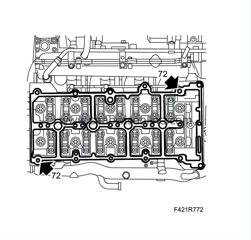
72.
|
Fit the guide sleeves and fit a new gasket onto the cylinder head.
|
Note
|
|
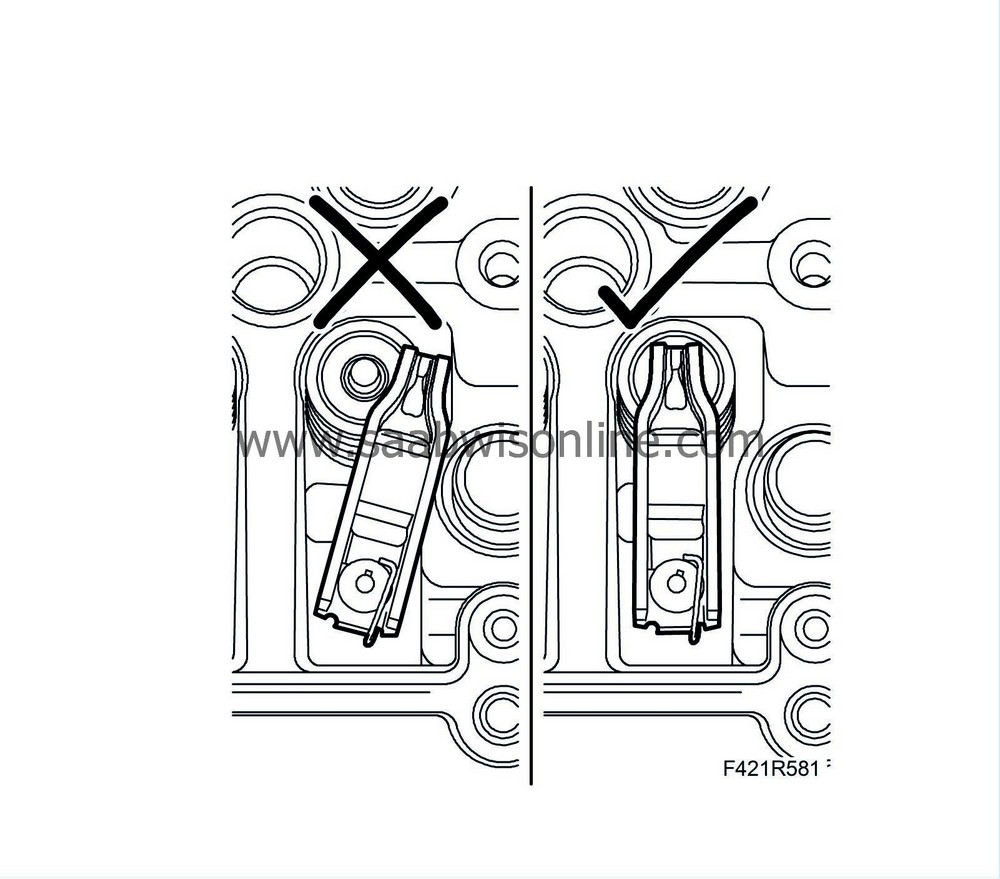
Check that all the rocker arms are positioned correctly on the valve stems.
|
|
|
73.
|
Fit the camshaft housing, tighten the bolts alternately. Make sure the guide sleeves are positioned correctly in the camshaft housing.
Tightening torque 25 Nm (18 lbf ft).
|
|
74.
|
Screw in the spacer sleeve against the cylinder head and fit the bolt.
|
|
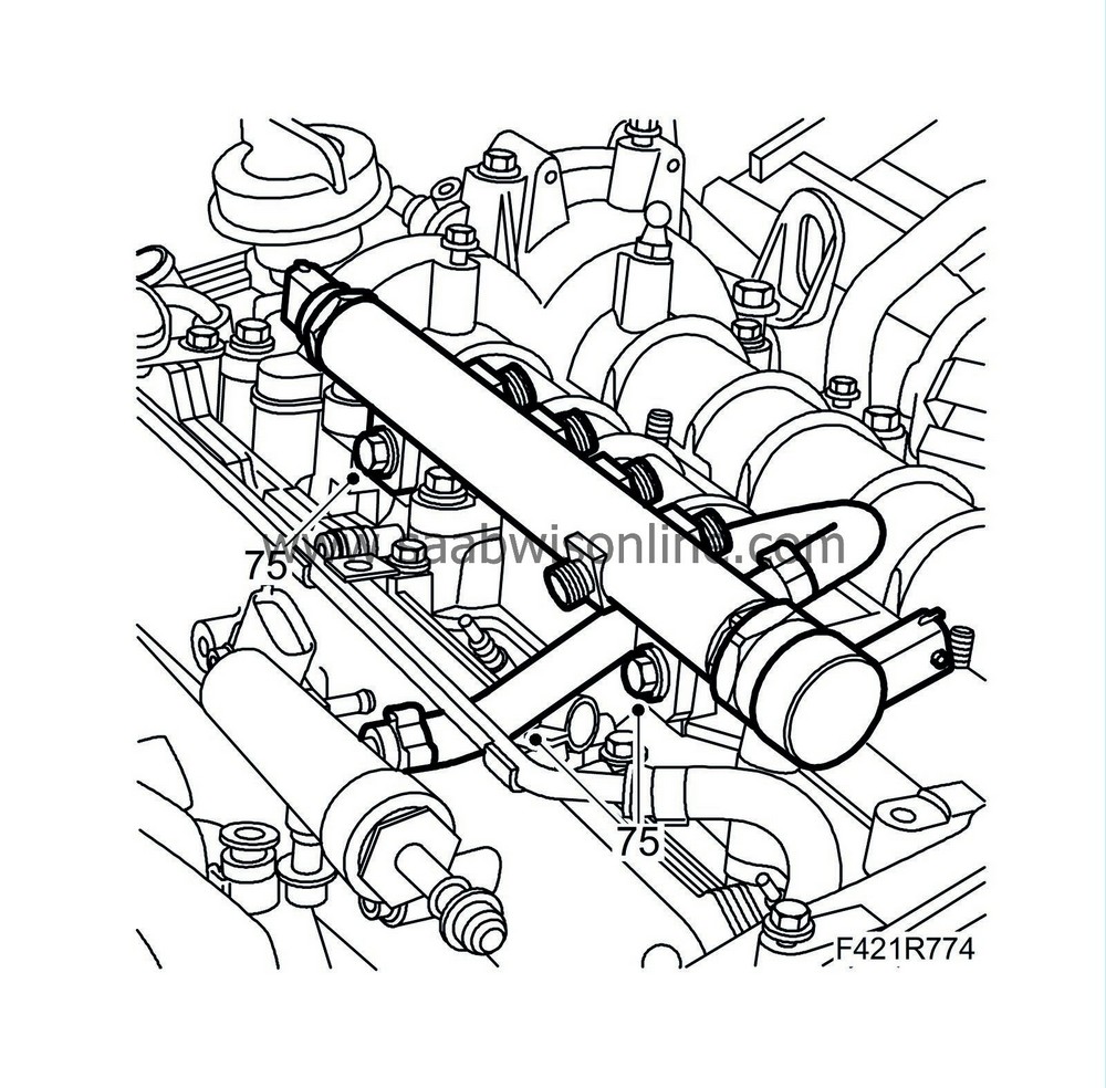
75.
|
Fit the fuel rail and hose.
|
|
77.
|
Fit the injectors according to the marks made earlier with new seals in the following order: 4-3-2-1.
Tightening torque 25 Nm (18 lbf ft).
|
|
78.
|
Check that the fuel pipe sealing surfaces are clean and not damaged. Fit the pipes without strain and screw on the nuts by hand to begin with. Tighten the nuts. Hold the injectors with an open spanner.
Tightening torque 25 Nm (18 lbf ft).
|
|
79.
|
Fit the fuel return hoses.
|
|
80.
|
Fit the fuel delivery pipe between the pump and the fuel rail.
Tightening torque 25 Nm (18 lbf ft).
|
|
81.
|
Fit the fuel return hose to the return fuel collector.
|
|
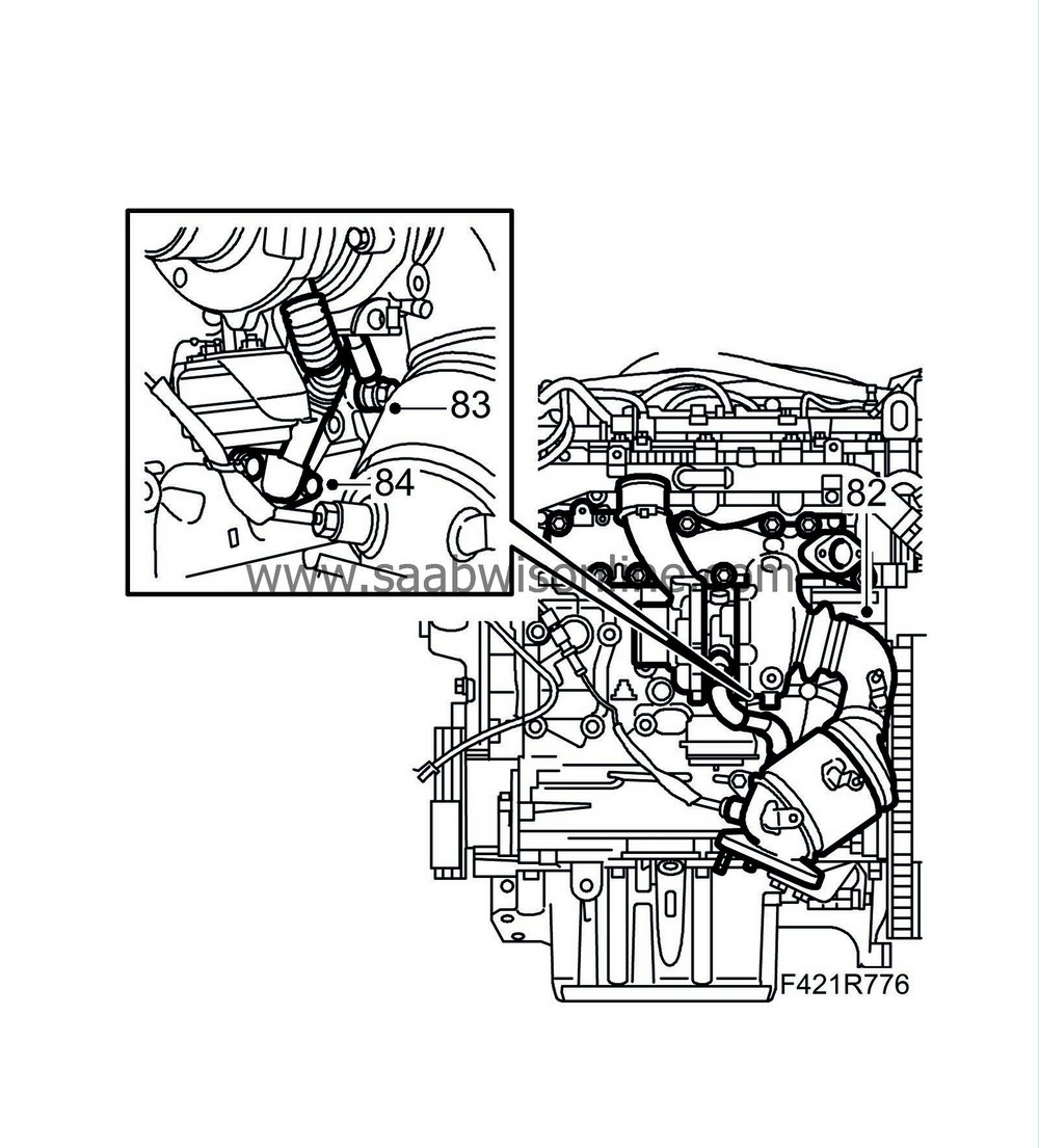
82.
|
Fit the turbocharger with catalytic converter. Use a new gasket.
Tightening torque 20 Nm (15 lbf ft)
|
|
83.
|
Fit the oil delivery pipe to the engine block with new gaskets.
Tightening torque 15 Nm (11 lbf ft)
|
|
84.
|
Fit the turbocharger oil return pipe with a new gasket.
Tightening torque 25 Nm (18 lbf ft).
|
|
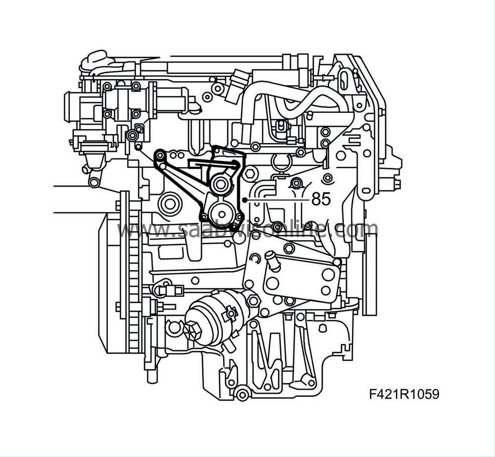
85.
|
Fit Actuator, combustion circulation (403). Press the control arm onto the ball joint using a suitable pair of pliers.
|
|
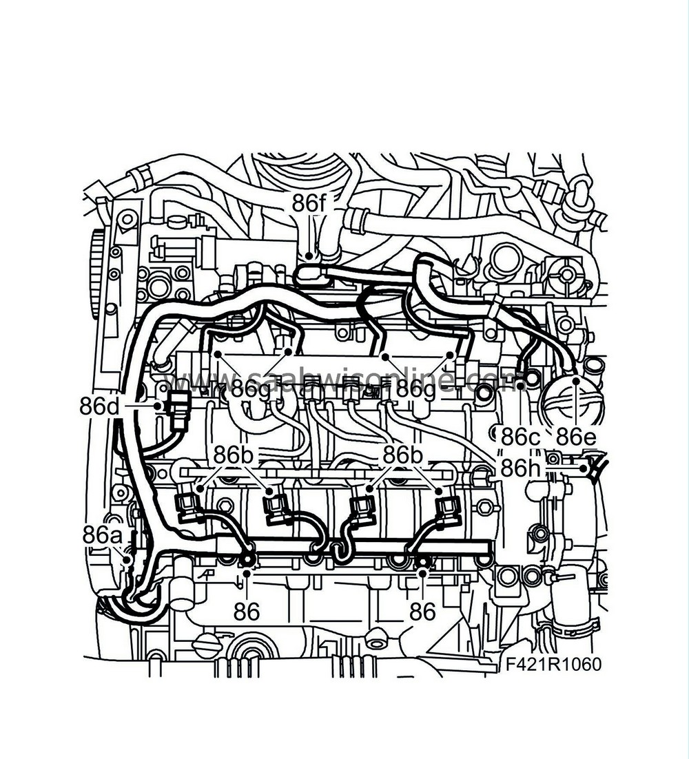
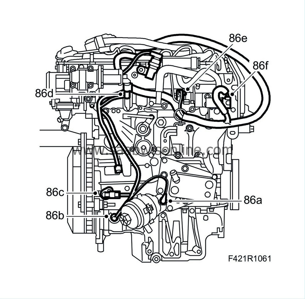
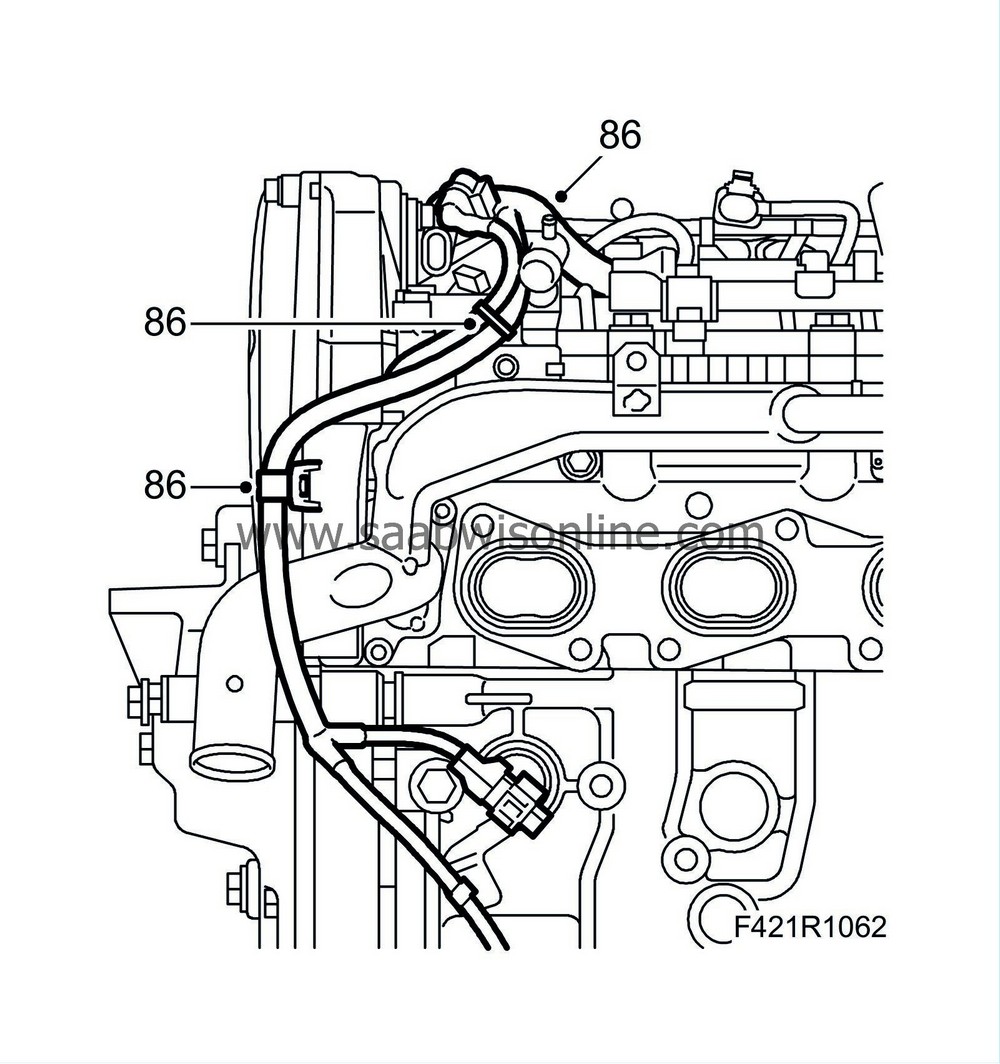
86.
|
Put the wiring harness in place. Fit the following connectors:
|
|
|
86.a.
|
Camshaft position sensor (555)
|
|
|
86.c.
|
Fuel pressure sensor (653)
|
|
|
86.d.
|
Fuel pressure control valve (652a)
|
|
|
86.e.
|
Throttle body actuator unit (604).
|
|
|
86.f.
|
Intake air sensor (688)
|
|
|
86.g.
|
Glow plug connector
|
|
|
86.h.
|
Coolant temperature sensor (202)
|
|
|
86.i.
|
Pressure switch, engine oil (44)
|
|
|
86.j.
|
Level sensor, engine oil (243)
|
|
|
86.k.
|
Crankshaft position sensor (345)
|
|
|
86.l.
|
Actuator, combustion circulation (403)
|
|
|
86.m.
|
EGR solenoid valve (606)
|
|
|
86.n.
|
Fuel quantity control valve, high-pressure pump (652b)
|
|
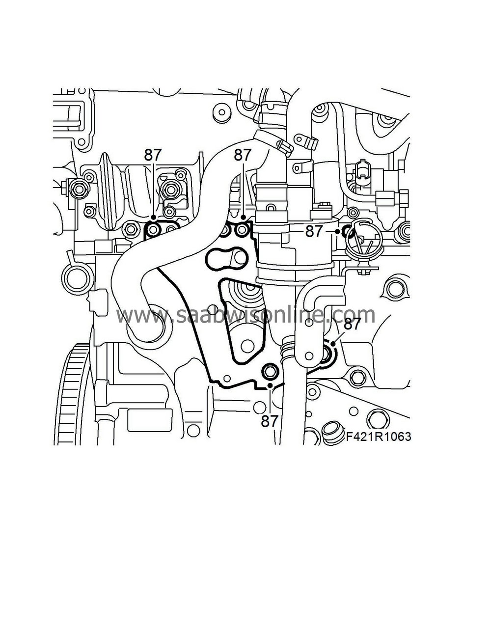
87.
|
Fit the oil trap bracket.
|
|
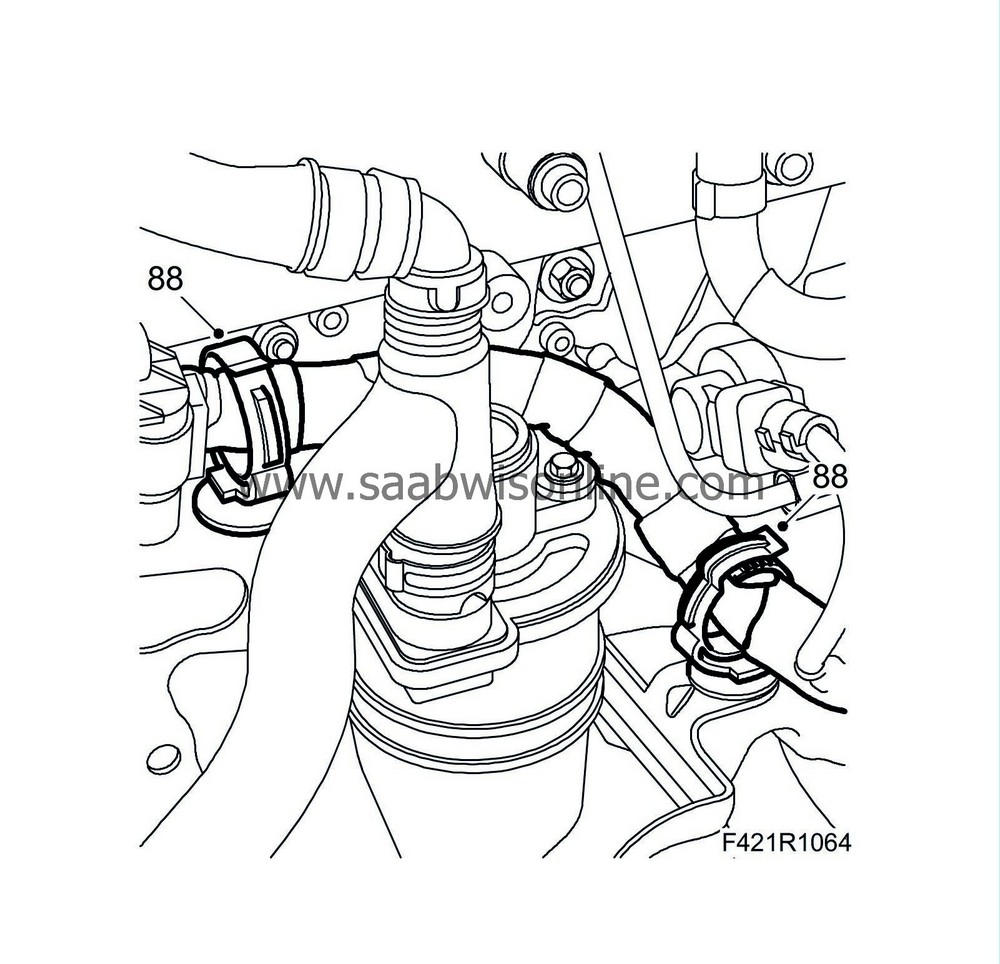
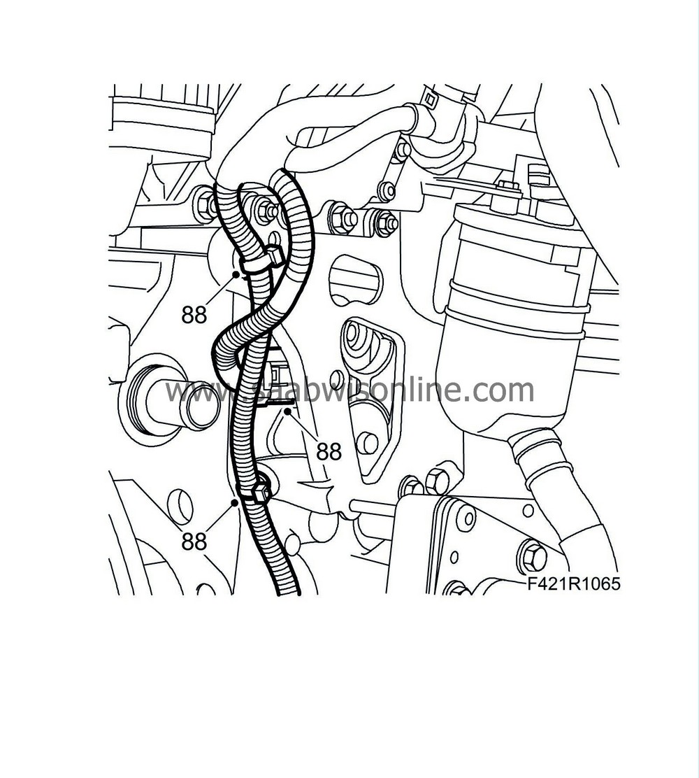
88.
|
Fit the wiring harness clips.
|
|
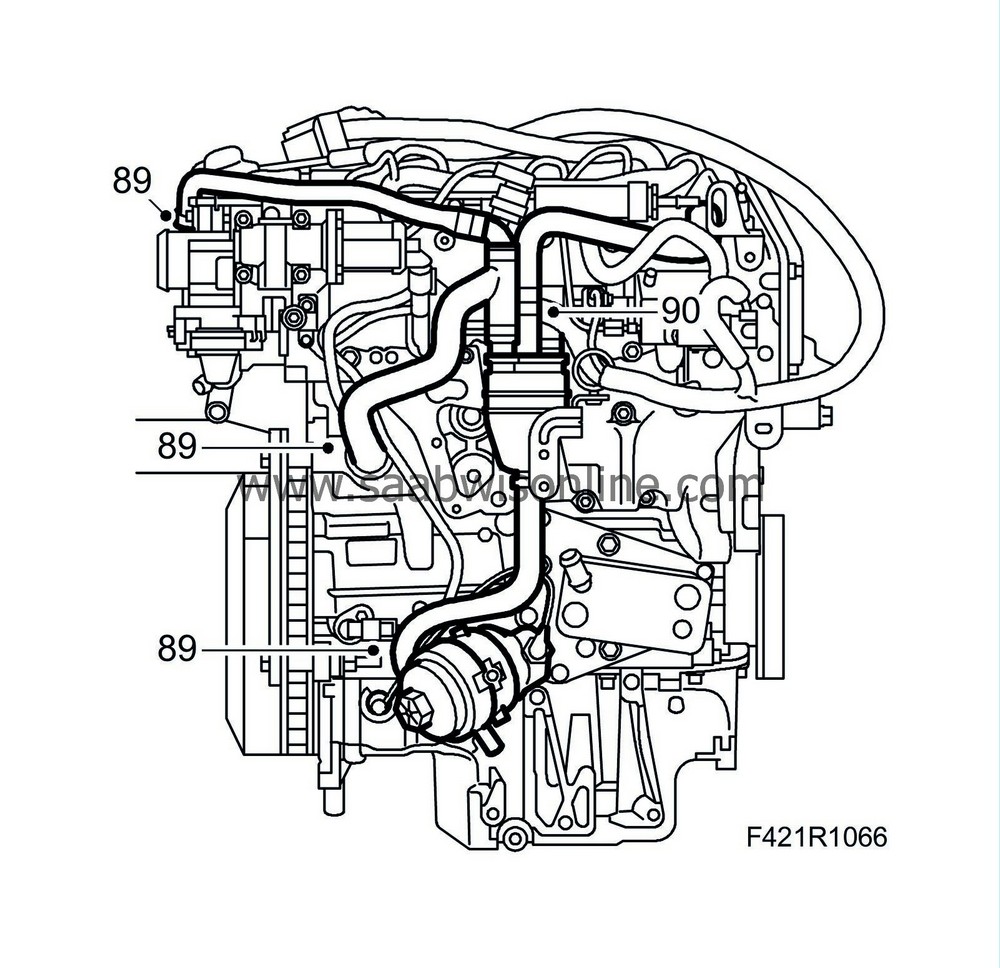
89.
|
Fit the crankcase ventilation hoses to the engine block, oil sump and oil filler pipe.
|
|
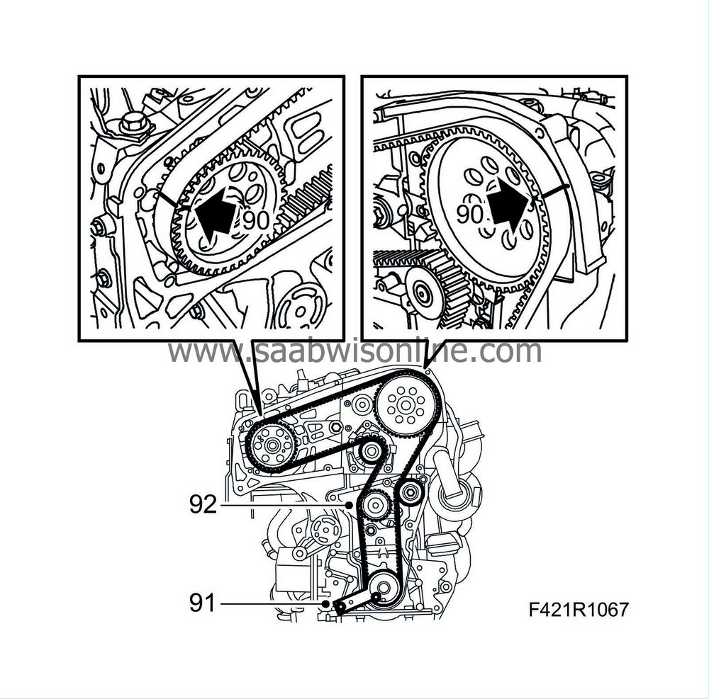
90.
|
Fit the timing belt so that the marks on the belt agree with the marks on the crankshaft, exhaust camshaft and fuel pump sprockets.
|
|
92.
|
Fit the belt tensioner without tightening the bolt.
|
|
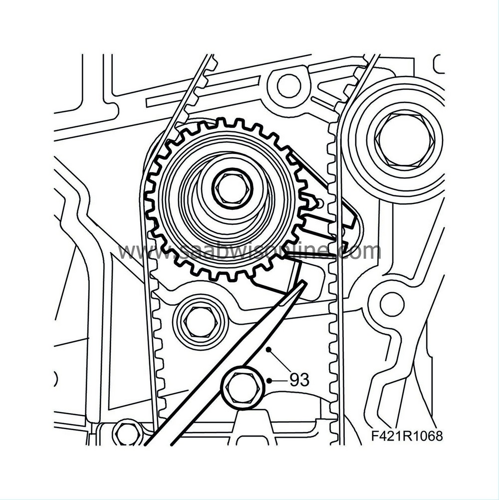
93.
|
Adjust so that the belt tensioner arrow is right in front of the mark by pressing the setting lever in the direction of the arrow. Tighten the belt tensioner using a large screwdriver and an M8 bolt for support.
Tightening torque 25 Nm (18 lbf ft)
|
|
94.
|
Remove the adjustment tool and turn the crankshaft 2 turns.
|
|
96.
|
Remove the tool and fit the plug on the camshaft cover and the bolt to the oil pump.
|
|
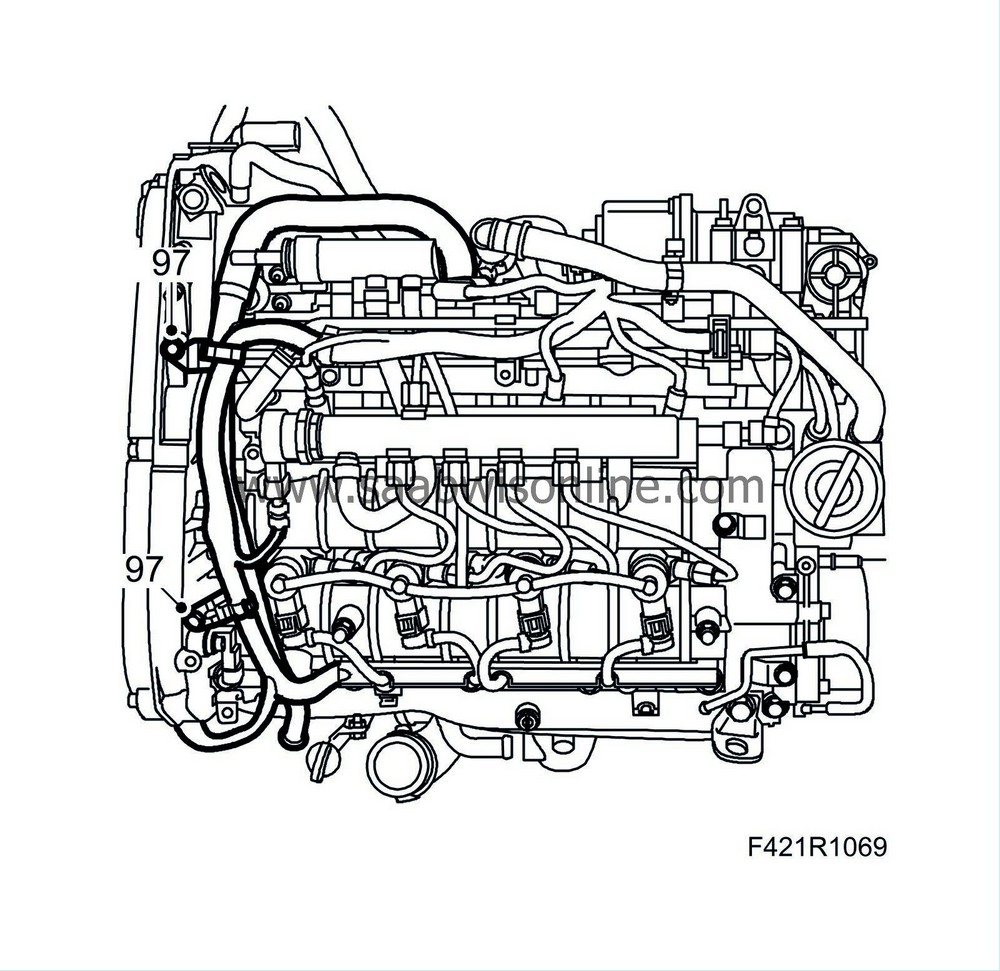
97.
|
Fit the crankcase ventilation pipe and hose on the camshaft housing.
|
|
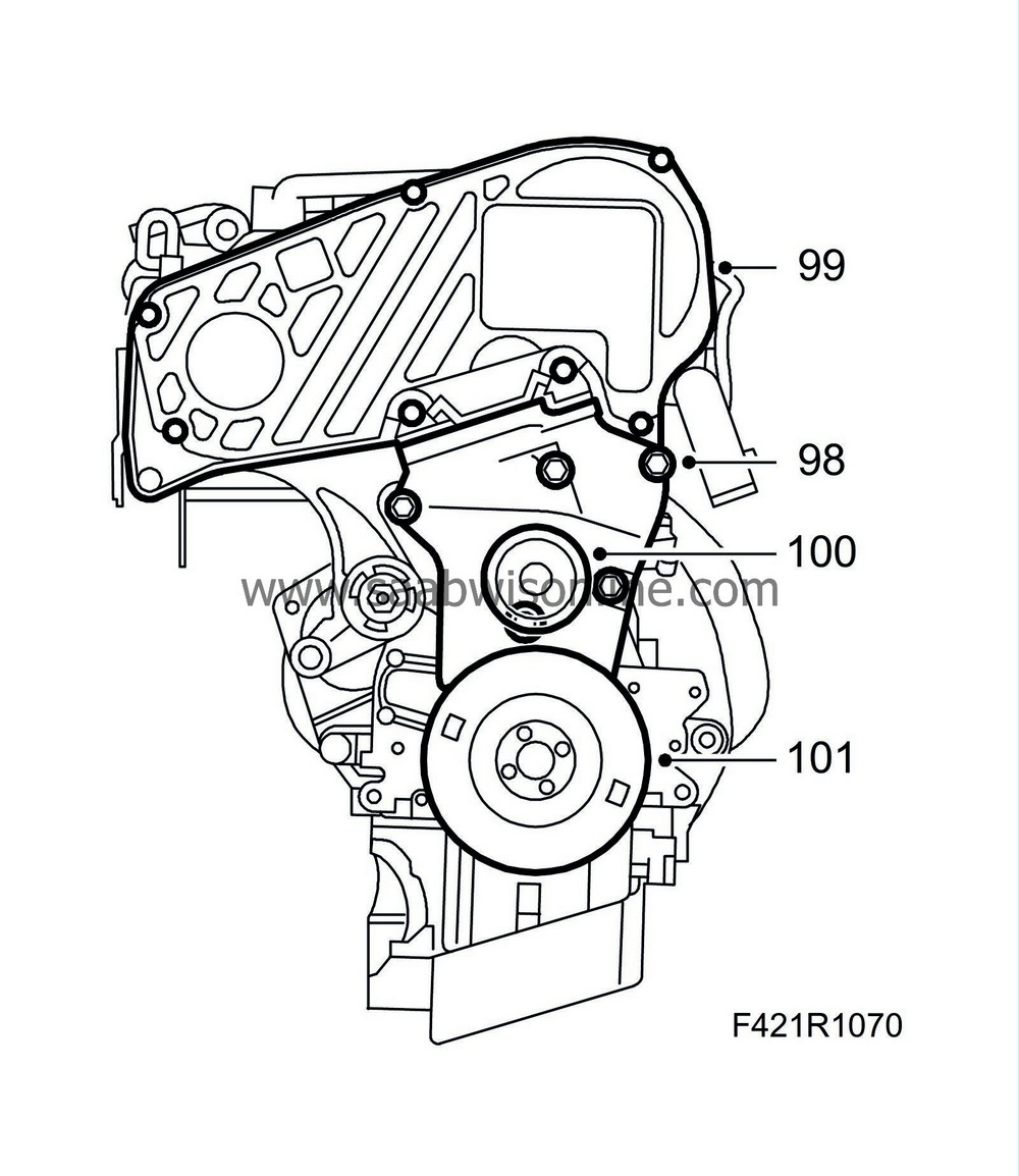
98.
|
Fit the lower timing cover.
|
|
99.
|
Fit the upper timing cover.
|
|
100.
|
Fit the idler pulley centre bolt on the lower timing cover.
Tightening torque 25 Nm (18 lbf ft)
|
|
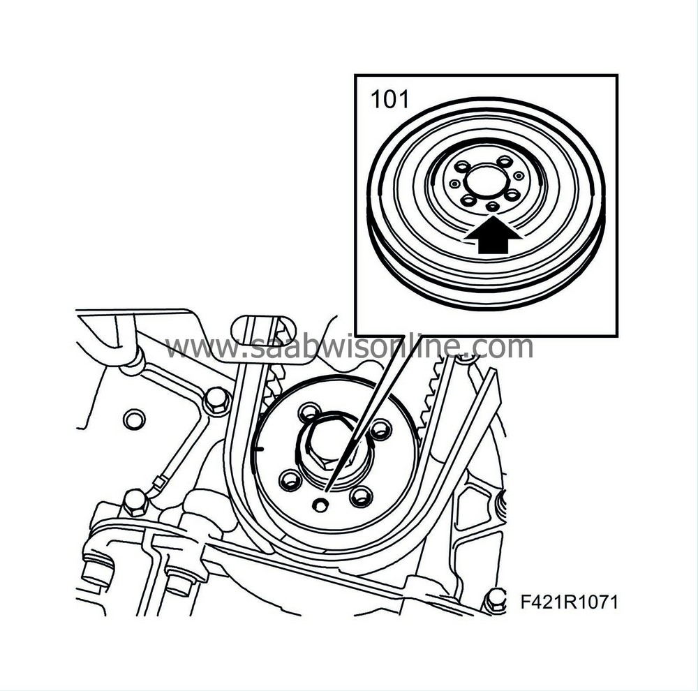
101.
|
Fit the crankshaft pulley.
|
Note
|
|
Make sure the guide pin is in its recess.
|
Tightening torque 25 Nm (18 lbf ft)
|
|
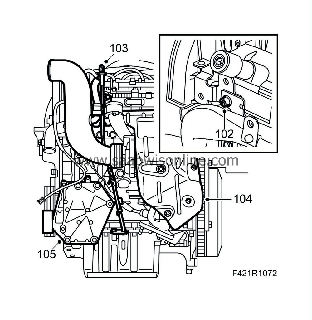
102.
|
Fit the bracket to the turbocharger intake manifold.
|
|
103.
|
Fit the dipstick tube.
|
|
104.
|
Fit the heat shield.
|
|
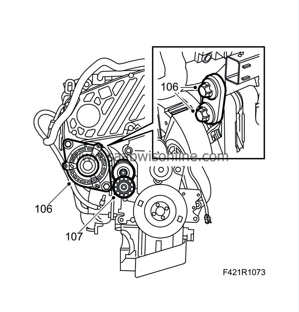
106.
|
Fit the generator.
|
|
107.
|
Fit the belt tensioner.
|
|
109.
|
Make sure the two guide sleeves are fitted on the engine and apply grease to the guide sleeves.
|
|
111.
|
Man
: Fit the gearbox to the engine.
Tightening torque, M10 40 Nm (30 lbf ft)
Tightening torque, M12 60 Nm (44 lbf ft)
|
|
112.
|
Aut
: Turn the torque converter so that the bolt holes agree with the holes in the driver plate and turn the engine so that the oval hole in the driver plate is opposite the starter motor opening. Lubricate the torque converter guide pin with grease.
|
|
113.
|
Aut
: Fit the gearbox to the engine. Remove
87 92 574 Holder
just before the gearbox is in place. Tighten the bolts between the engine and the gearbox.
Tightening torque, M10 40 Nm (30 lbf ft)
Tightening torque, M12 60 Nm (44 lbf ft)
|
|
114.
|
Aut
: Press the torque converter against the driver plate. Fit the plug.
|
|
115.
|
Aut
: Apply
Thread locking adhesive, Loctite 270
to the bolts holding the torque converter to the driver plate.
|
Note
|
|
Use the original bolts with associated washers. The torque converter will be ruined if the bolts that are used that are too long.
|
|
|
116.
|
Aut
: Turn the engine clockwise with the pulley and tighten the bolts one at a time starting with the oval hole in the driver plate.
Tightening torque 30 Nm (22 lbf ft)
|
|
119.
|
Aut
: Lubricate the pipes with
Vaseline, non-acidic
and fit the oil cooler hoses. The pipes will press holes in the seals when fitted.
|
|
120.
|
Fit the front catalytic converter bracket.
|
|
121.
|
Fit the starter motor with bracket for the coolant pipe and wiring harness.
Tightening torque 24 Nm (18 lbf ft).
|
|
122.
|
Fit a new oil filter.
|
|
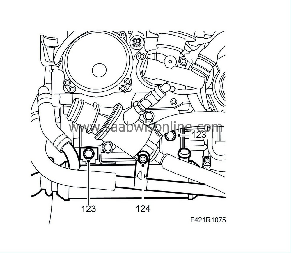
123.
|
Fit the EGR cooler with new seals.
Tightening torque to cylinder head 25 Nm (18 lbf ft)
Tightening torque to EGR valve 20 Nm (15 lbf ft)
Tightening torque to exhaust manifold 20 Nm (15 lbf ft)
|
|
124.
|
Fit and connect the coolant pipes to the oil cooler and engine.
|
|
125.
|
Fit the wiring harness and connect it to the generator and starter motor.
|
|
126.
|
Lift the power unit onto the subframe.
|
|
127.
|
Tighten the torque arm to the subframe.
Tightening torque front arm 60 Nm +90° (44 lbf ft +90°)
Tightening torque rear arm 80 Nm (59 lbf ft)
|
|
128.
|
Connect the wiring harness to the EHPS unit.
|
|
129.
|
Remove the lifting eye.
|


