(248-2672) Engine runs on 3 cylinders/misfiring
Symptom: The engine runs on three cylinders or misfires
Check engine lamp lights.
9-3: diagnostic trouble code P0201, P0202, P0203 or P0204 detected.
9-5: diagnostic trouble code P0261, P0262, P0263 or P0264 detected.
|
TECHNICAL SERVICE BULLETIN
|
|
Bulletin Nbr:
|
248-2672
|
|
Date:
...........
|
Juni 2007
|
|
Market:
|
enligt separat lista
|
|
|
Engine runs on 3 cylinders/misfiring
|
Saab 9-5 M06-07.5 with engine variant Z19
Saab 9-3 M05-07 with engine variant Z19
On account of vibrations on the wiring harness connector the surface between the connector pins and sleeves on the injectors can corrode; this in turn can result in poor contact. As a consequence one or more injectors do not supply the cylinders with fuel. More often than not it is the injector on cylinder three that suffers from poor contact. On some vehicles the wiring harness may also be damaged.
In the event of customer complaints the following procedure must be undertaken.
Symptom description
The engine runs on three cylinders or misfires
Check engine lamp lights.
9-3:
diagnostic trouble code P0201, P0202, P0203 or P0204 detected.
9-5:
diagnostic trouble code P0261, P0262, P0263 or P0264 detected.
|
Note
|
|
A certain degree of misfiring can occur without generating a diagnostic trouble code.
|
93 189 918 Kit, connector housing
92 150 191 Cable tie for cable channel, 2x
92 150 191 Cable tie for wiring harness, 2x
510 82 46 Splices, 2x
861 21 52 Heat-shrink hose (available from SPX. The kit is enough for 7 contact housings)
PVC tape for the wiring harness, see www.3m.com, or www.tesa.com
Fabric tape for the protective cover, see the websites above for suitable tape.
Contact Protect CRC (www.crcindustries.com) or Contact 61 or similar
|
Note
|
|
The method concerns the replacement of the wiring harness with connector housing. The method below applies to the injector to cylinder 3 as an example. The method is also suitable for other injectors.
|
Fault diagnosis
Establish which injector is not working by dismantling and reassembling the connectors on the injectors one at a time while the engine is idling. If the running of the engine is not affected when the connector is dismantled, rectify the cylinder in question by replacing the injector's wiring harness and connector as described in the method below.
|
1.
|
Remove the upper engine cover.
|
|
2.
|
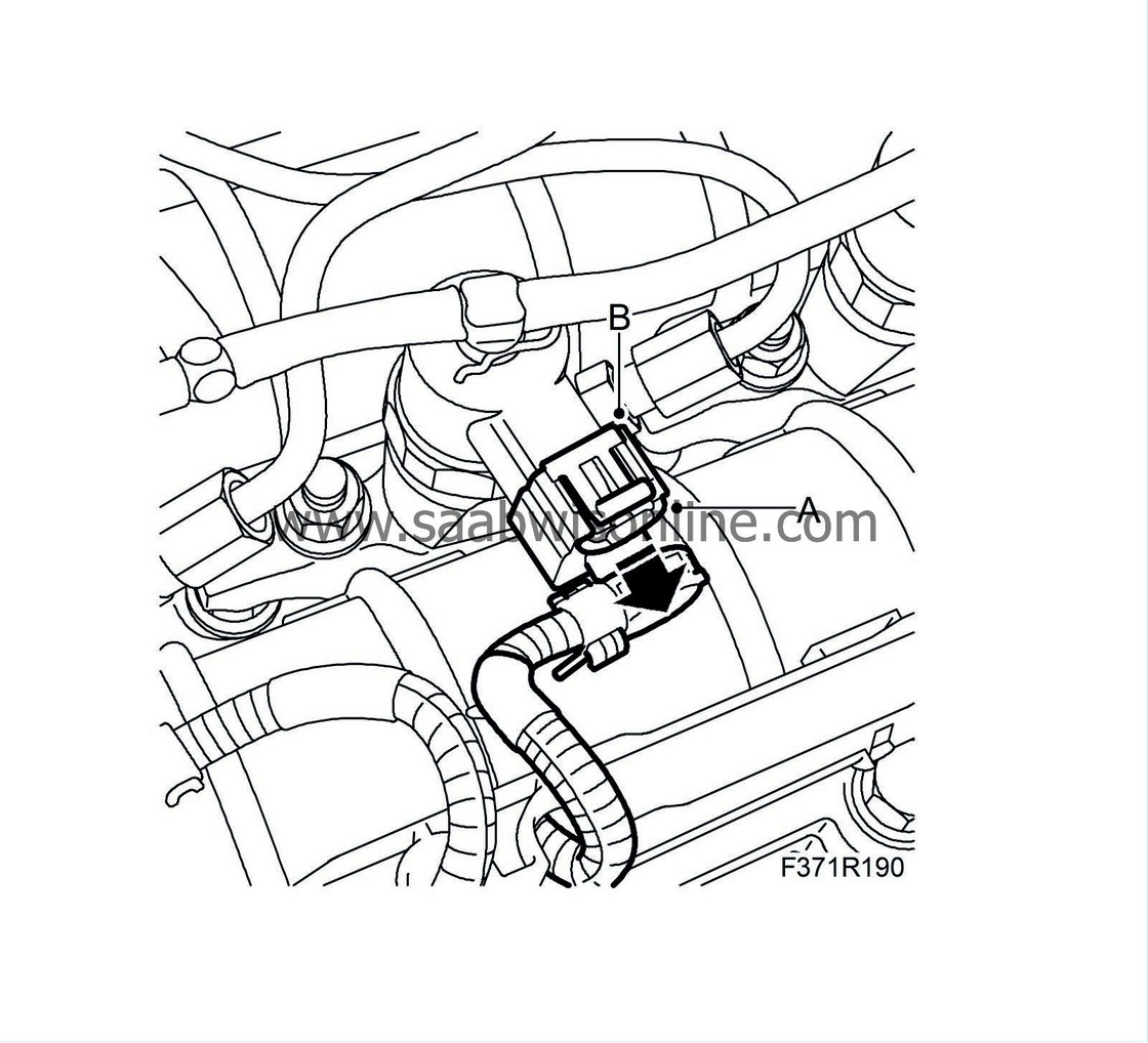
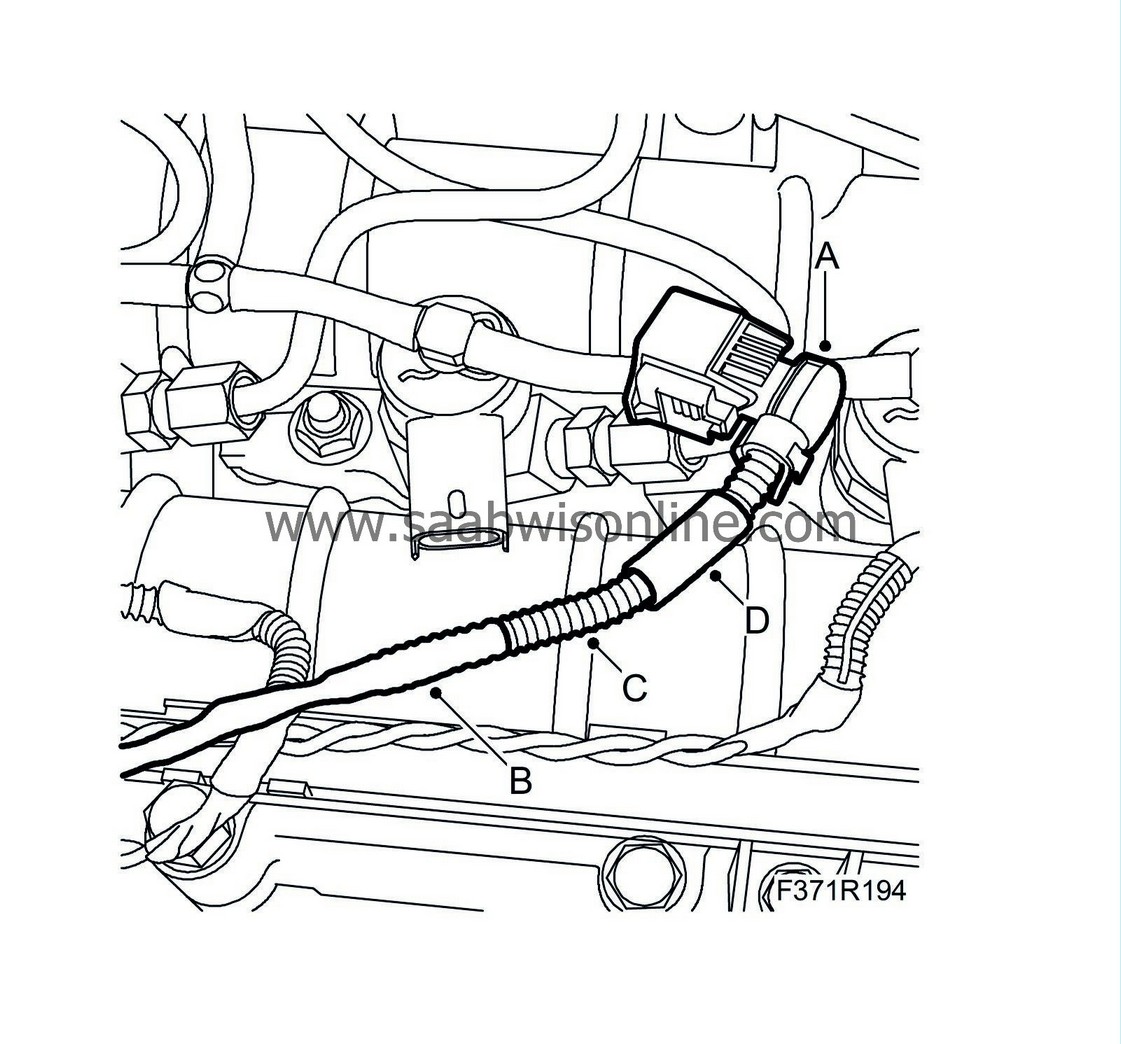
Remove the connectors on all injectors, by first opening the secondary retainer (A), then press down the catch (B) and pull the connector from the injector.
|
|
3.
|
Clean the injector's connector. Use Contact Protect CRC or Contact 61 or similar.
|
|
4.
|
Remove the cable channel:
|
|
|
•
|
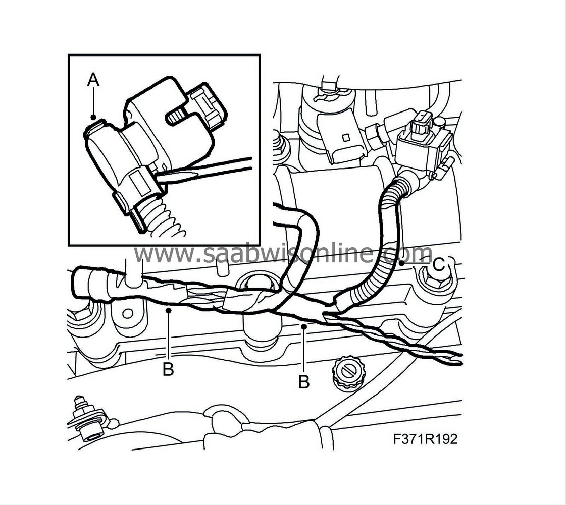
Release the vacuum hose (A) from the channel.
|
|
|
•
|
Remove the 2 screws (B).
|
|
|
•
|
Open and divide the channel at the clip (C).
|
|
5.
|
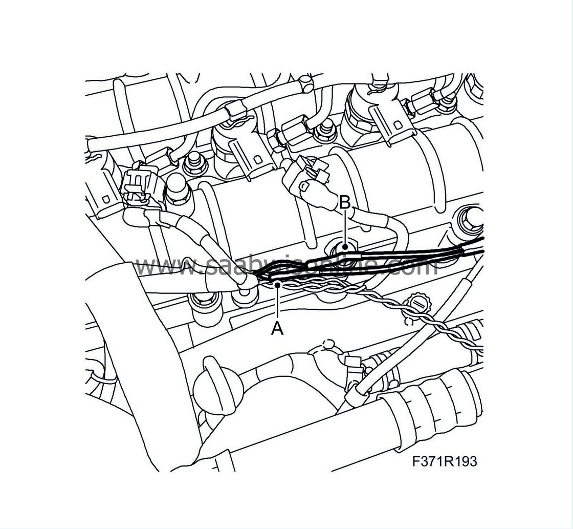
Dismantle the rear cover (A) using a small screwdriver. The rear cover will be reused on the new connector housing. Remove the tape (B) and the protective cover (C) on the wiring harness to the injector 3.
|
|
6.
|
Replace the connector:
|
|
|
•
|
Connect the 2 supplied 2.5 mm cables to the new connector, ensure the terminals lock.
|
|
|
•
|
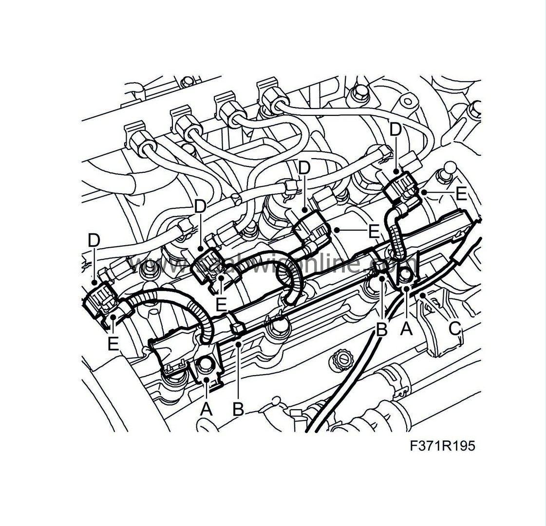
Cut the cable to pos. 1 close to the branch to the 1st injector. Ensure that there is sufficient room for a joint and that the joints will not touch each other if several connectors are changed. The joint should lie inside the channel. Strip back the cable to the old contact housing. Fit heat-shrink hose (A) to the new wiring harness and join the new leads to pos. 1 to the existing harness using a splice. Use 86 12 061 pliers for 1.5 - 2.5 mm² (part of special tool kit 86 12 079, 86 12 483 or 86 12 939)
|
|
|
•
|
Cut the cable to pos. 2. The splice must be positioned in the channel after the splice on the cable 1, closer to the branch to the injector 2. Put the old connector to one side. Thread heat-shrinkable tubing (B) onto the new wiring harness and assemble the new cable from pos. 2 with the existing wiring harness using a splice.
|
|
|
•
|
Position the heat-shrinkable tubing over the splices and heat to fit.
|
|
7.
|
Fit the protective cover (C), fit the rear cover (A). Ensure the retainers mate properly and that the protective cover locks in the cutout on the rear cover. Fit tape (B) over the transition between the protective cover and the splices on the wiring harness to injector 3. Fit tape (D) around the protective cover.
|
|
8.
|
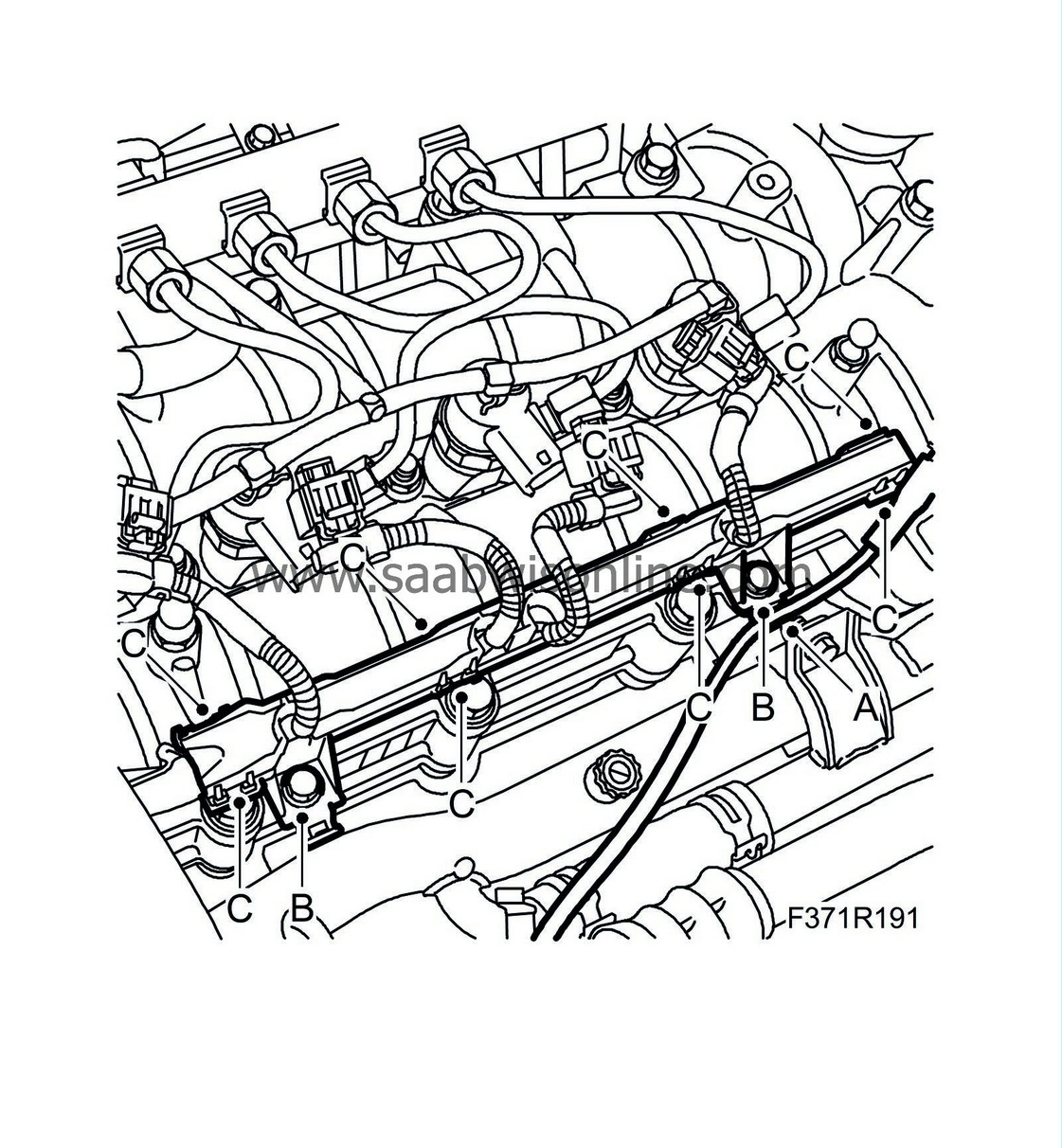
Assemble the lower section of the channel using 2 screws (A) and place the cables in the channel and close it. If the channel locks poorly, fit 2 cable ties (B) to secure. Connect the vacuum hose (C) to its terminal.
|
|
9.
|
Fit the connectors (D) on the injectors and lock the secondary retainers (E).
|
|
10.
|
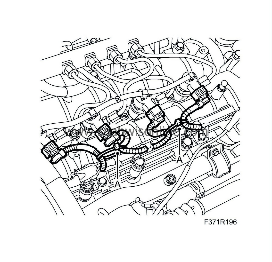
Secure 2 cable ties (A) to hold together the cables for cyl. 1-2 & 3-4.
|
|
11.
|
Fit the engine cover.
|
|
12.
|
Erase the diagnostic trouble codes
|
|
Warranty/Time Information
|
In the case of customer complaint and if the car is
within the warranty period
, use the following information to fill out the claim:
Failed Object: 37115
Fault/Reason code: 61
Location code: 09
Repair/Action code: 05
Time: 0.6 hr


