(234-2680) Changed methods, high-pressure pump, intake manifold/seal, Z19DTH
|
TECHNICAL SERVICE BULLETIN
|
|
Bulletin Nbr:
|
234-2680
|
|
Date:
...........
|
September 2007
|
|
Market:
|
Se separat lista
|
|
|
Changed methods, high-pressure pump, intake manifold/seal, Z19DTH
|
Saab 9-3 and 9-5 with engine alternative Z19DTH.
This bulletin advises of a changed method for replacing the
- high-pressure pump
- intake manifold/seal, Z19DTH (only the method for the high-pressure pump has been changed which means that the time for the intake manifold/seal is affected)
The standard times will accordingly be changed and come into force immediately. WIS-edition 2008-1 will contain the information.
See EPC
|
To remove, high-pressure pump
|
|
1.
|
Open the bonnet and fit a wing cover over the right-hand wing.
|
|
2.
|
Remove the battery cover and undo the battery's negative cable.
|
|
3.
|
Remove the upper engine cover as well as the insulation.
|
|
4.
|
9-3
: Remove the right-hand engine mounting, see WIS - Engine - 4-cyl diesel - Basic engine - Engine pad, right-hand, Z19.
|
Note
|
|
Make a note of the location of the screws.
|
|
|
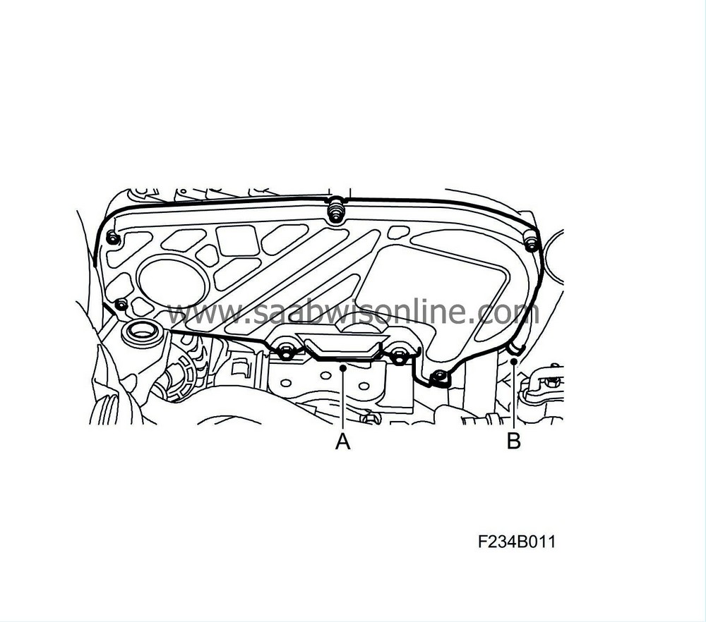
5.
|
Remove the screws for the upper timing cover (A), open the clip (B). Lift out the wiring harness and lift away the cover.
|
|
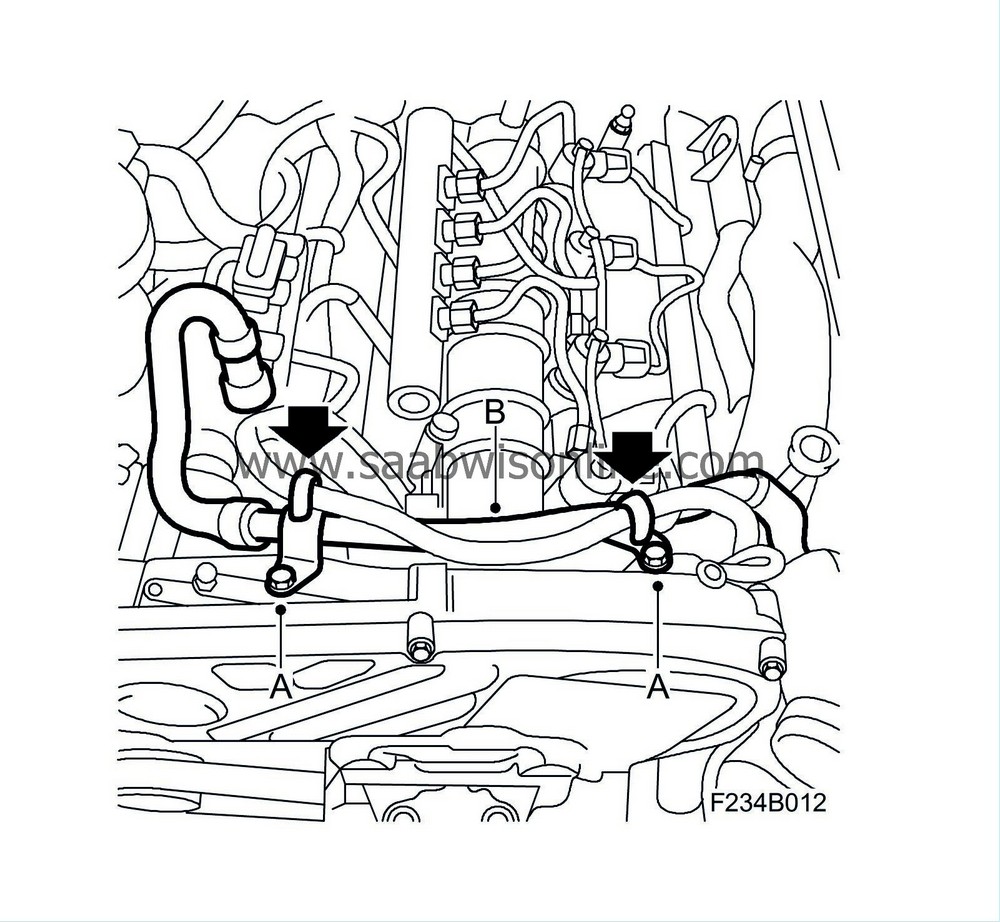
6.
|
Undo the screws (A) for the crankcase ventilation pipe (B) and the hose from the camshaft housing.
|
|
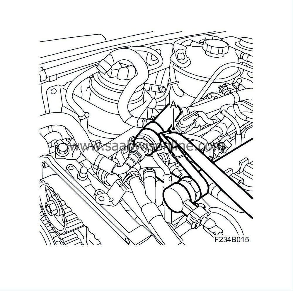
7.
|
Certain cars:
Unplug the connector (A). Remove the bracket (B).

|
|
8.
|
Remove the hoses on the high-pressure pump:
|
|
|
-
|
Plug all connections with plugs from kit 92 01 697.
Keep a rag available to collect any spilled fuel.
|
|
|
-
|
Undo the clip and remove the fuel supply hose (A) from the high-pressure pump. Plug the hose.

|
|
|
-
|
Undo the clip and remove the return hose (B) on the high-pressure pump. Plug the hose.
|
|
|
-
|
Unplug the fuel pressure sensor's connector (C) from the high-pressure pump.
|
|
|
-
|
Remove the screws (D) for the return fuel collector.
|
|
|
-
|
Remove the high-pressure fuel line (E).
Plug the jet pipe.
|
|
9.
|
When replacing the high-pressure pump
: Fold away the return fuel collector and secure to the jet pipe using a cable tie (A).
|
|
10.
|
When replacing the intake manifold/seal
: Remove the return fuel line (A) from the return fuel collector. Use 83 95 261 Fuel line tool. Keep a rag available to collect any spilled fuel. Plug the connections.

|
|
11.
|
When replacing the intake manifold/seal
: Undo the hoses from the return fuel collector (B). Remove the return fuel collector. Plug the connections.
|
|
12.
|
Position a rag under the pump to avoid dropping the pulley wedge.
|
|
13.
|
Remove the pulley's nut:

|
|
|
-
|
Rotate the engine so that it is possible to fit 2 two hex socket head screws (A) M6 X40 (30 mm unthreaded and 10 mm thread) through the holes in the pulley and to the threads in the high-pressure pump bracket.
|
|
|
-
|
Remove the pulley's nut (B).
|
|
14.
|
Remove the high-pressure pump from the pulley by pressing out the pump using 32 025 005 Puller (A), counterholding with a 30 mm box/open-end wrench (B). Remove the puller.

|
|
15.
|
Remove the high-pressure pump:
|
|
|
-
|
Remove the nuts and washers (A), use a magnet to avoid dropping the washers.

|
|
|
-
|
Lift out the pump, retain the wedge.
|
|
To fit, high-pressure pump
|
|
1.
|
Fit the wedge to the pump and fit the pump in place. Fit the washers and nuts (A). It is important that the wedge engages in the groove on the pulley.
Tightening torque 25 Nm (18 lbf ft)
|
|
2.
|
Fit the nut (B) to the high-pressure pump's pulley.
Tightening torque 50 Nm (36 lbf ft).
|
|
3.
|
Remove the screws (A) securing the pulley.
|
|
4.
|
When replacing the high-pressure pump
: Remove the cable tie (A).
|
|
5.
|
Fit the hoses to the pump:
|
|
|
-
|
Remove all plugs on the pump's connections.
|
|
|
-
|
Remove the plug and fit the high-pressure fuel line (E). If it is difficult to fit the fuel pipe in place, undo the fuel rail's retaining bolts slightly.
Tightening torque, fuel pipe 25 Nm (18 lbf ft).
|
|
|
-
|
Remove the plug and fit the fuel supply hose (A) and the clip to the pump.
|
|
|
-
|
Remove the plug and fit the return hose (B) and the clip to the high-pressure pump.
|
|
|
-
|
Plug in the fuel pressure sensor's connector (C) to the high-pressure pump.
|
|
|
-
|
Fit the screws (D) for the return fuel collector.
Tightening torque 9 Nm (7 lbf ft)
|
|
6.
|
When replacing the intake manifold/seal
: Fit the hoses (B) for the return fuel collector. Fit the return fuel line (A).
|
Note
|
|
Make a note of the location of the screws.
|
|
|
7.
|
Fit the screws to the upper timing cover (A) and fit the wiring harness to the clip (B).
|
|
8.
|
Certain cars:
Fit the bracket (B) and plug in the connector (A).
|
|
9.
|
Fit the screws (A) for the crankcase ventilation pipe (B) and the hose to the camshaft housing.
|
|
10.
|
9-3
: Fit the right-hand engine mounting, see WIS - Engine - 4-cyl diesel - Basic engine - Engine pad, right-hand, Z19.
|
|
11.
|
Fit the insulation as well as the upper engine cover.
|
|
12.
|
Fit the battery's negative cable and the battery cover.
|
|
13.
|
Carry out the Procedures after disconnecting the battery, in accordance with WIS - Electrical system - Charging systems - Adjustment/Replacement.
|
|
14.
|
Switch the engine on and off.
|
|
15.
|
Remove the wing cover and close the bonnet.
|
|
Warranty/Time Information
|
In the case of customer complaint and if the car is
within the warranty period
, use the following information to fill out the claim:
High-pressure pump 9-5
Failed Object: 24110
Fault/Reason code: X
Location code: 09
Repair/Action code: 01/02
Time: 0.9 hr
High-pressure pump 9-3
Failed Object: 24110
Fault/Reason code: X
Location code: 09
Repair/Action code: 01/02
Time: 1.5 hr
Additional time CV (71102): 0.2 hr
Intake manifold/seal 9-5
Failed Object: 25110/25118
Fault/Reason code: X
Location code: 09
Repair/Action code: 01/02
Time: 2.9 hr
Intake manifold/seal 9-3
Failed Object: 25110/25118
Fault/Reason code: X
Location code: 09
Repair/Action code: 01/02
Time: 3.1 hr
Additional time CV (71102): 0.2 hr


