Camshaft covers, removed engine
|
|
Camshaft covers, removed engine
|
|
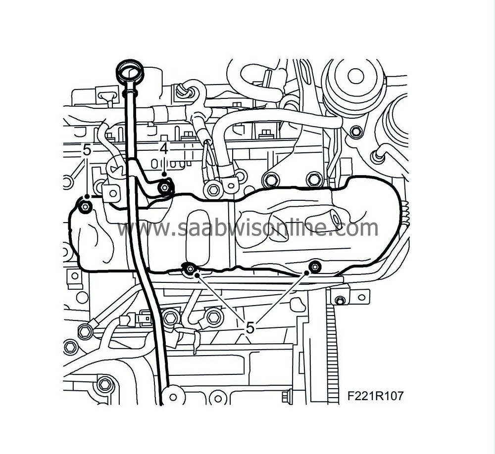
4.
|
Remove the bolt holding the dipstick guide tube and lift away the tube. Remove the O-ring.
|
|
5.
|
Remove the heat shield of the front exhaust manifold.
|
|
6.
|
Detach the intermediate exhaust pipe from the turbo and from the front exhaust manifold.

|
|
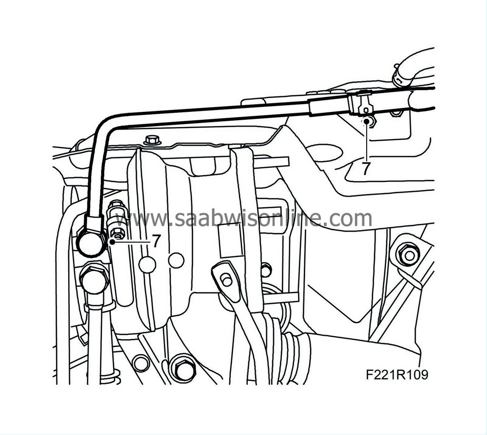
7.
|
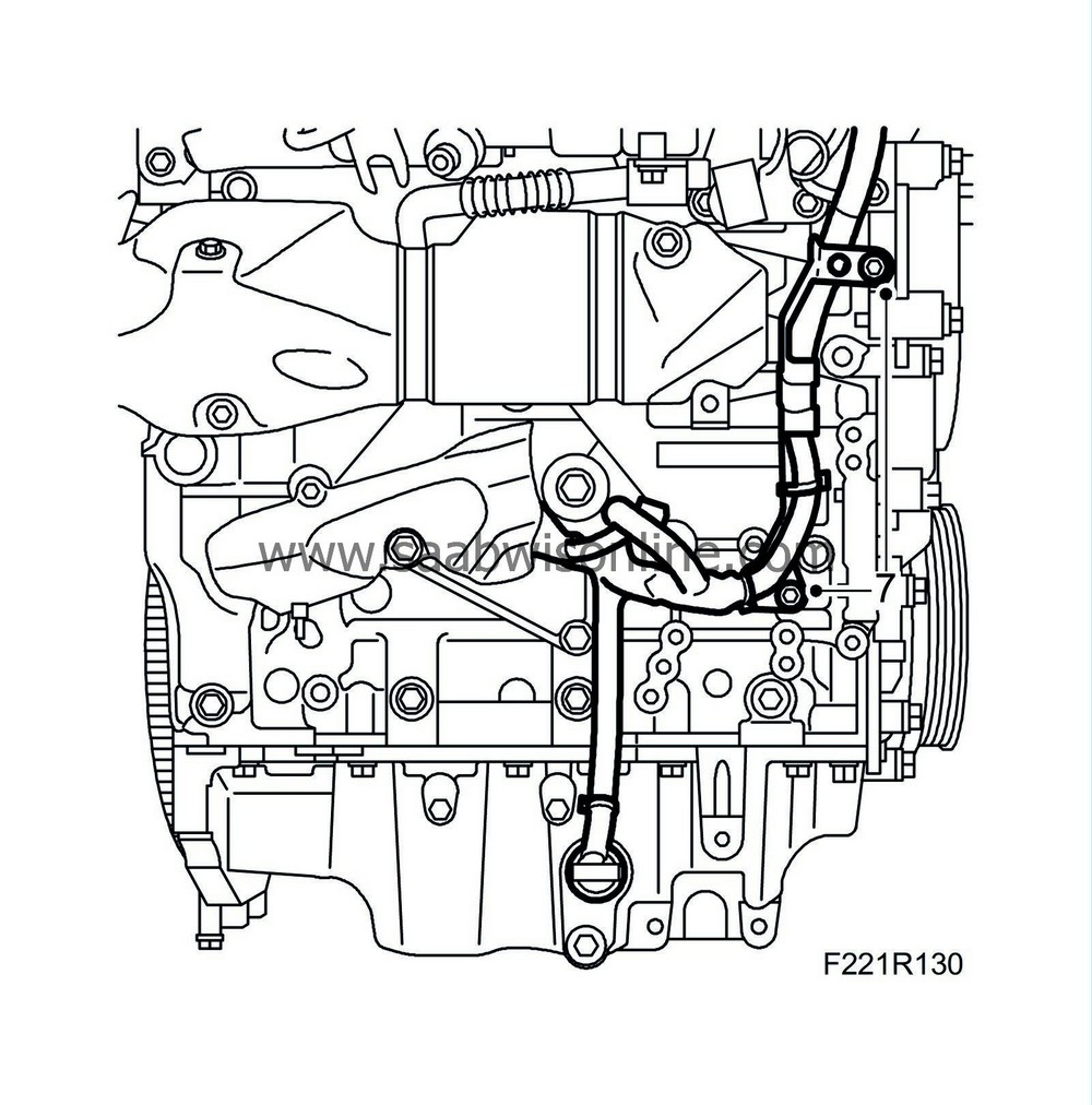
Detach the return coolant pipe from the turbocharger and heat shield.
|
|
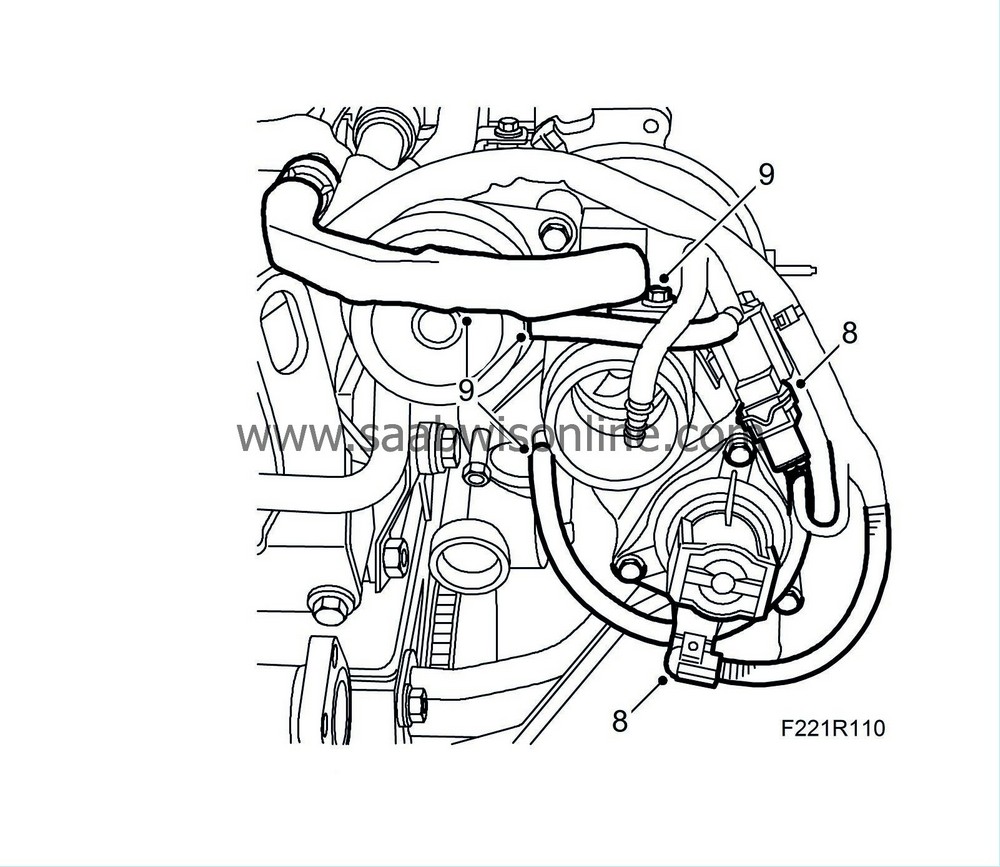
8.
|
Unplug the bypass valve connector.
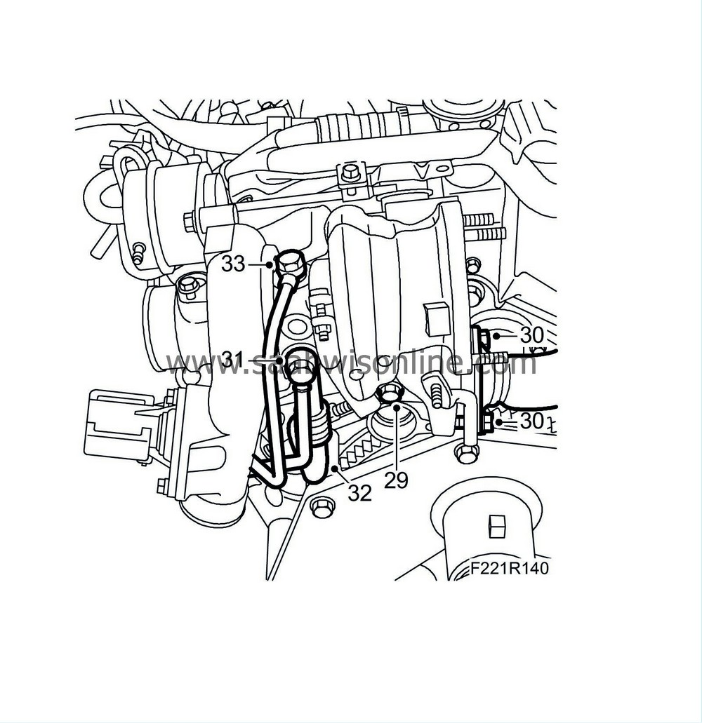
|
|
9.
|
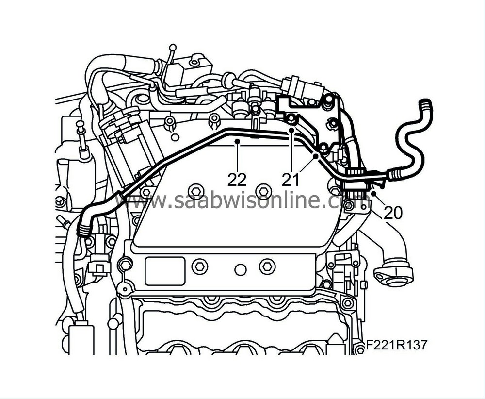
Detach the vacuum hoses and the crankcase ventilation pipe from the turbo.
|
|
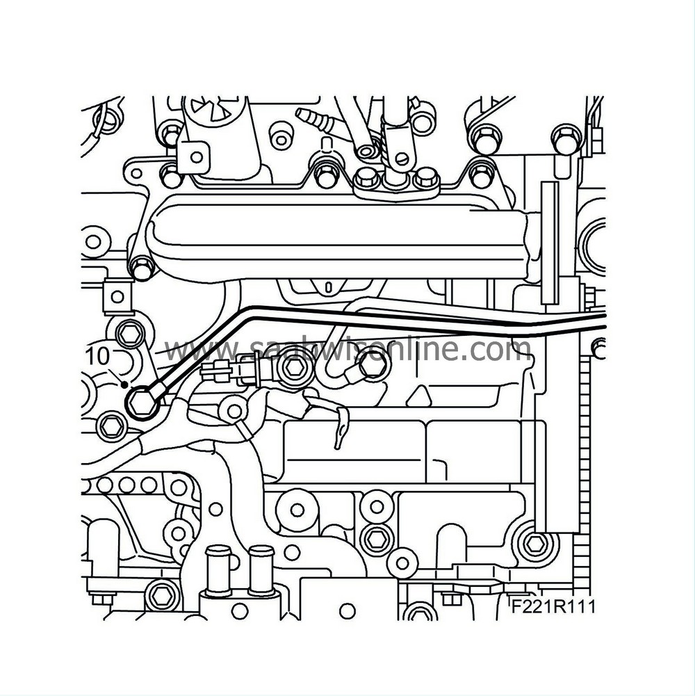
10.
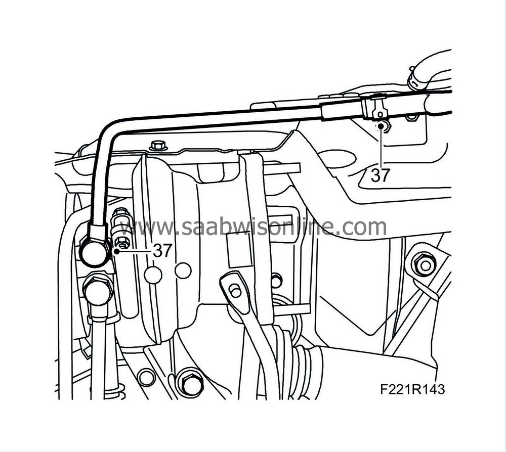
|
Detach the oil delivery pipe from the engine and remove the bolt.
|
|
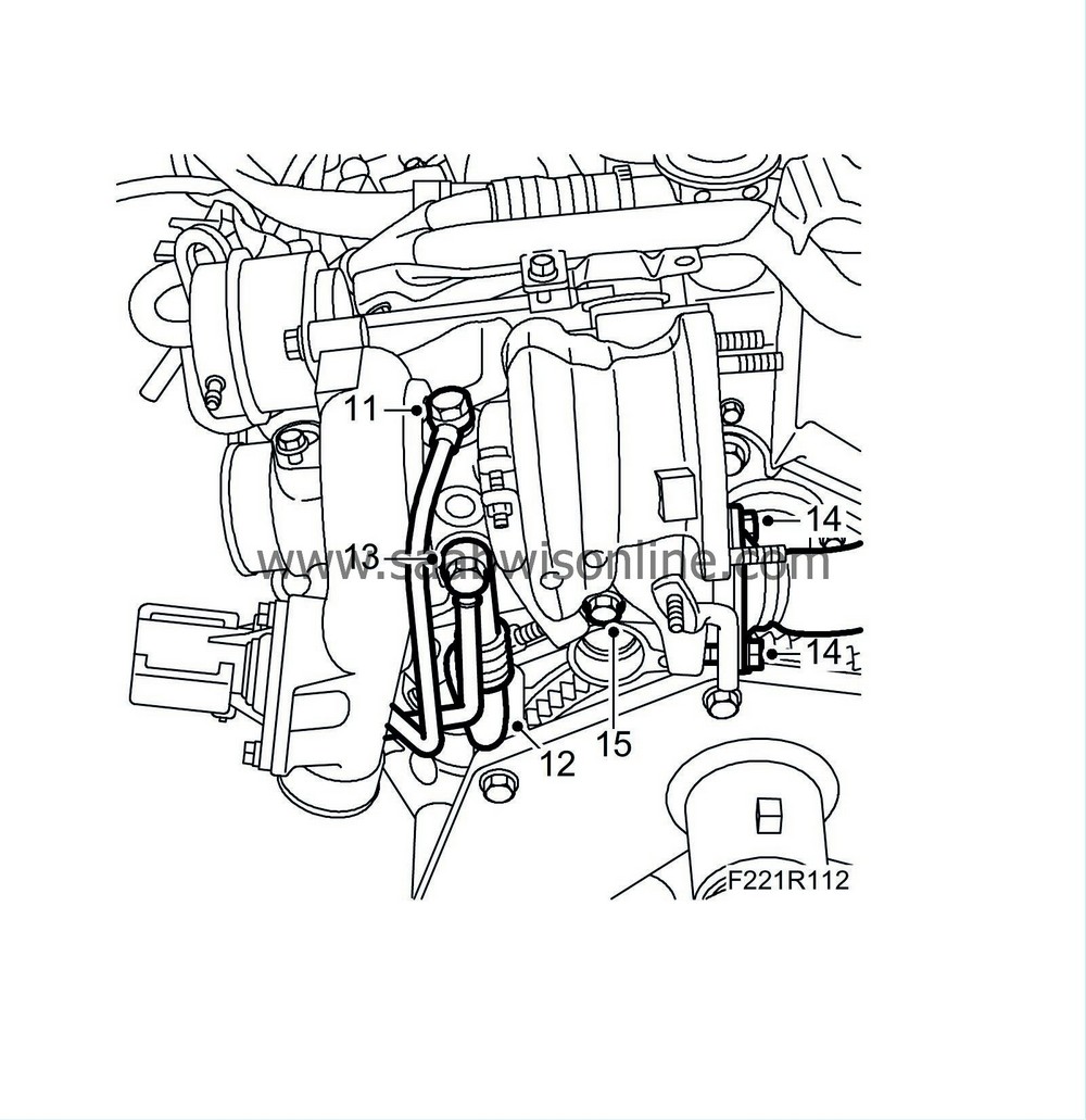
11.
|
Remove the oil delivery pipe's banjo screws from the turbo. Lift away the pipe.
|
|
12.
|
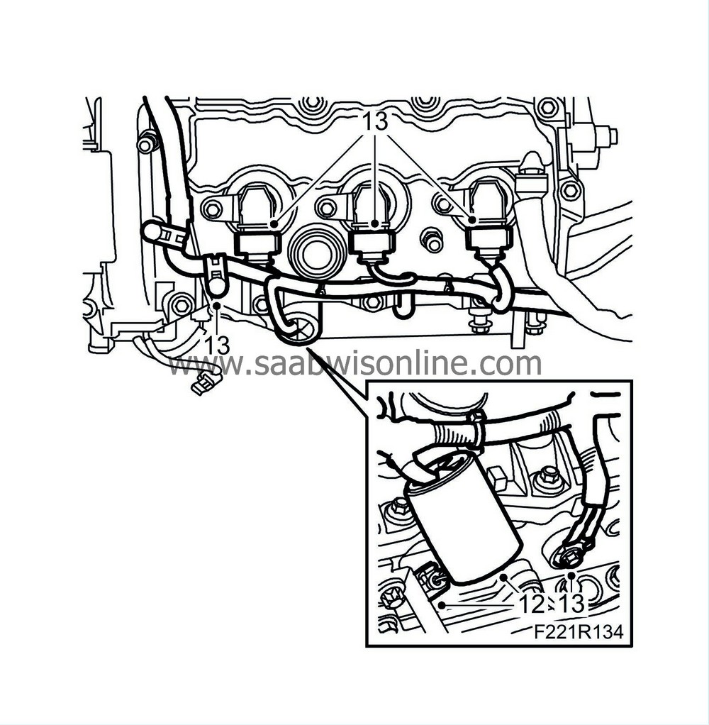
Remove the turbocharger oil return pipe from the turbocharger.
|
|
13.
|
Remove the coolant pipe's banjo screw from the turbocharger.
|
|
14.
|
Remove the nuts holding the rear intermediate exhaust pipe from the turbocharger.
|
|
15.
|
Remove the screw holding the turbocharger to the bracketing using a socket and a long pull rod.
|
|
16.
|
Remove the turbocharger.
|
|
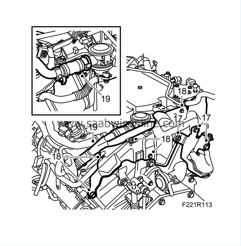
17.
|
Remove the upper mounting of the front catalytic converter.
|
|
18.
|
Remove the heat shield between the turbocharger and engine.
|
|
19.
|
Remove the secondary intake manifold.
|
|
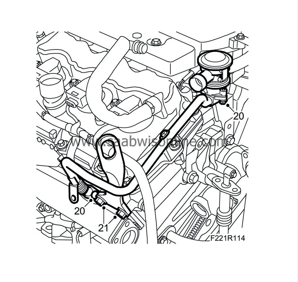
20.
|
Remove the front secondary air pipe and the valve.
|
|
21.
|
Remove the front lifting eye.
|
|
22.
|
Remove the engine vent pipe from the intake manifold.

|
|
23.
|
Remove the corner bracket from the intake manifold.
|
|
24.
|
Unplug the connectors of the injectors' wiring harness.
|
|
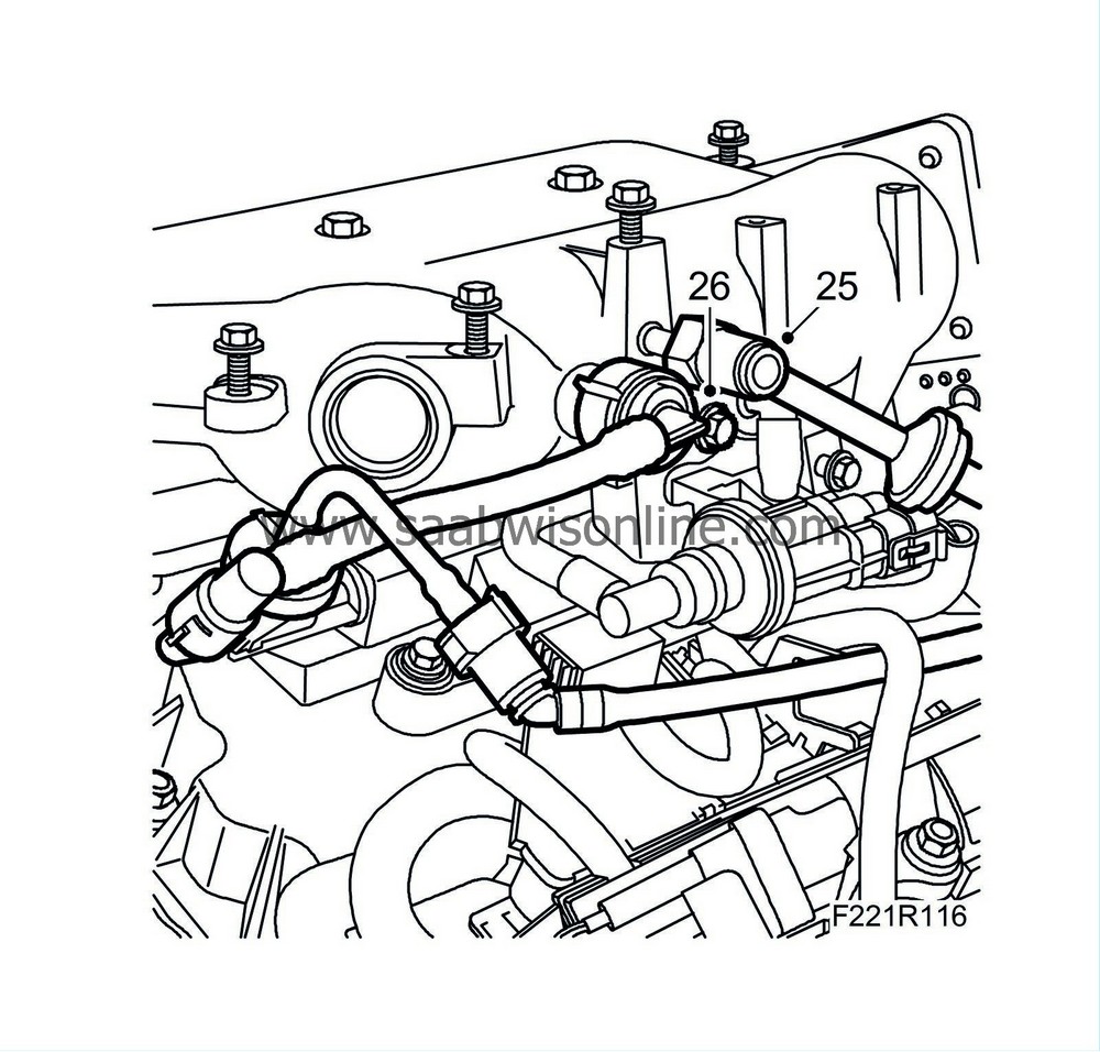
25.
|
Detach the brake vacuum hose from the intake manifold and venturi valve.
|
|
26.
|
Detach the crankcase ventilation pipes from the intake manifold.
|
|
27.
|
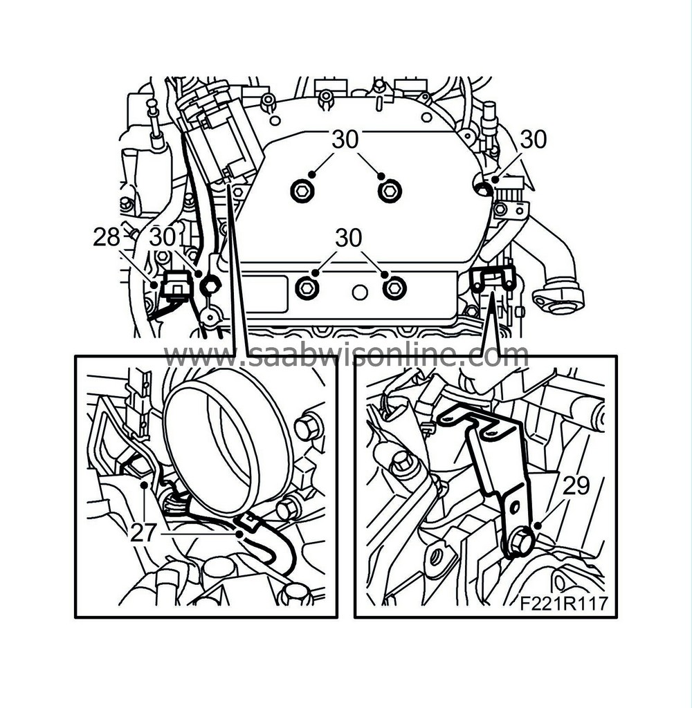
Unplug the throttle body connector and remove the cable from the clip.
|
|
28.
|
Unplug the fuel pressure sensor connector.
|
|
29.
|
Blow clean around the intake manifold base. Loosen the secondary air valve mounting and twist it down.
|
|
30.
|
Lift up the wiring harness so that the fuel pressure sensor is exposed. Remove the bolts and carefully lift off both intake manifolds as a unit. Remove the gasket and cover the inlet duct.
|
|
31.
|
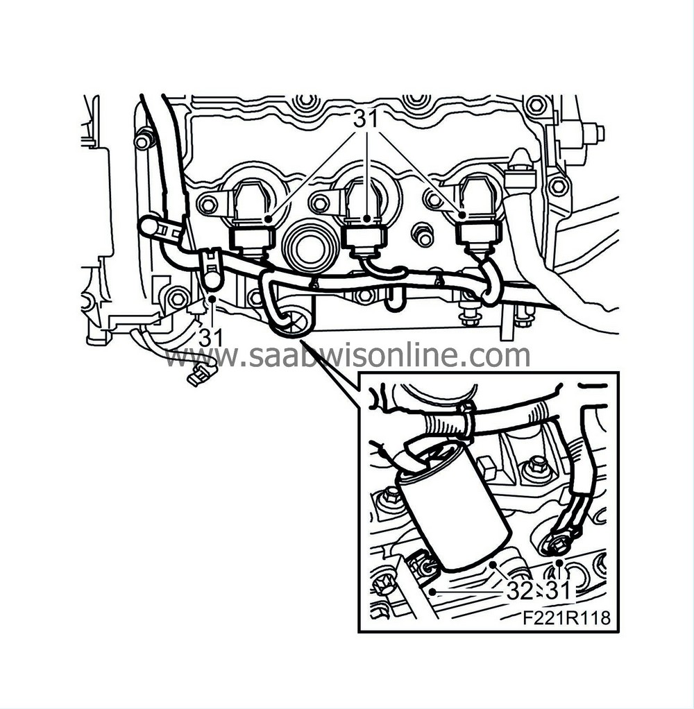
Unplug the connectors of ignition coils 2, 4 and 6 and detach the front ground connections.
|
|
32.
|
Raise the heat shield and unplug the coolant temperature sensor connector.
|
|
33.
|
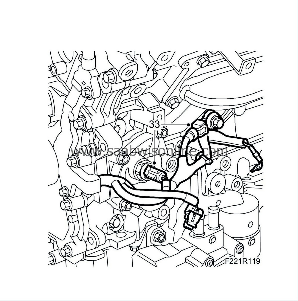
Remove the knock sensor and unplug the oil pressure sensor connector.
|
|
34.
|
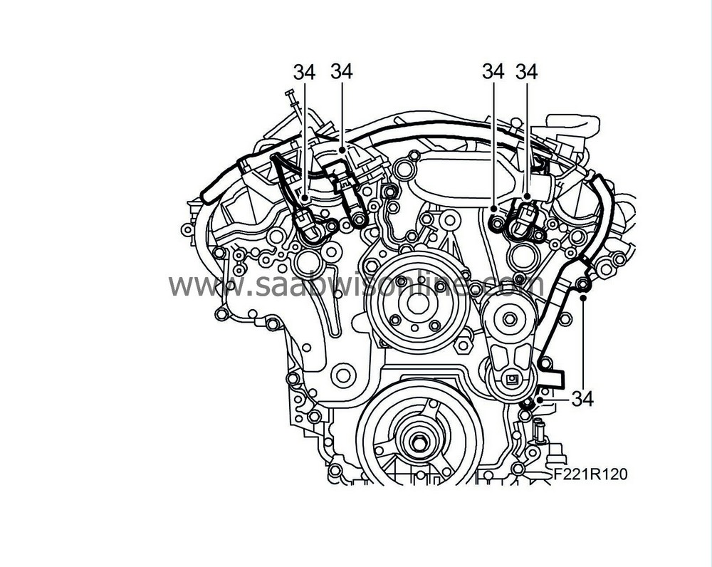
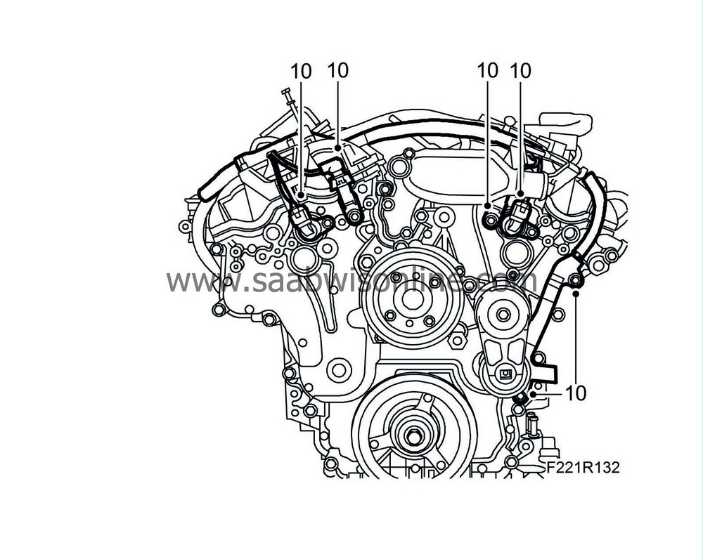
Remove the solenoid valve of the front and rear camshafts plus the rear camshaft position sensor.
|
|
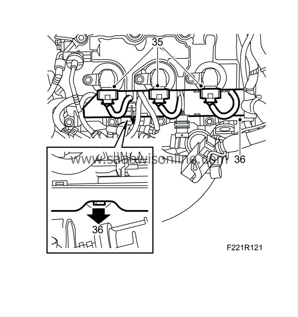
35.
|
Unplug the connectors of ignition coils 1, 3 and 5.
|
|
36.
|
Detach the cable duct from the timing cover.
|
|
37.
|
Remove the wiring harness from its anchorages.

|
|
38.
|
Secure the wiring harness on the rear of the engine using a cable tie.
|
|
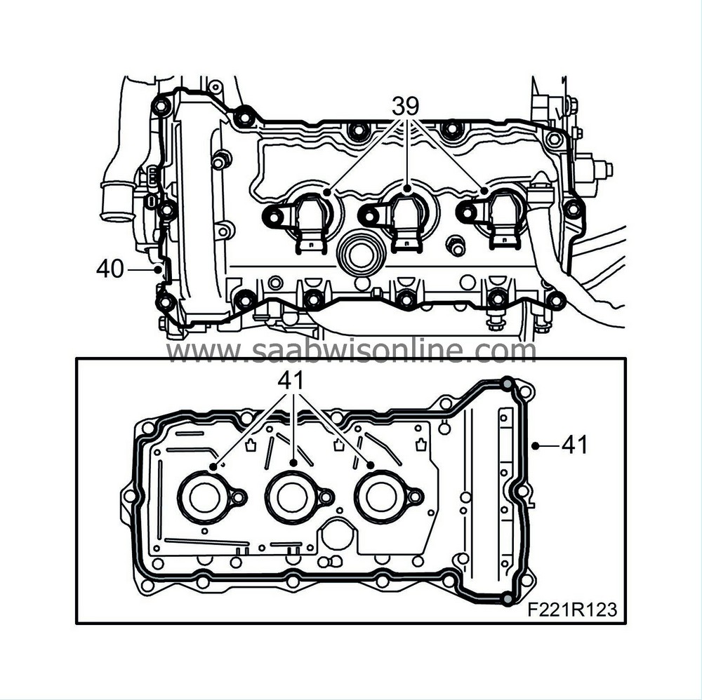
39.
|
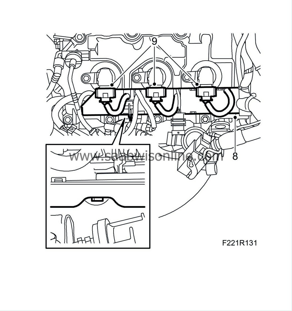
Remove ignition coils 2, 4 and 6.
|
|
40.
|
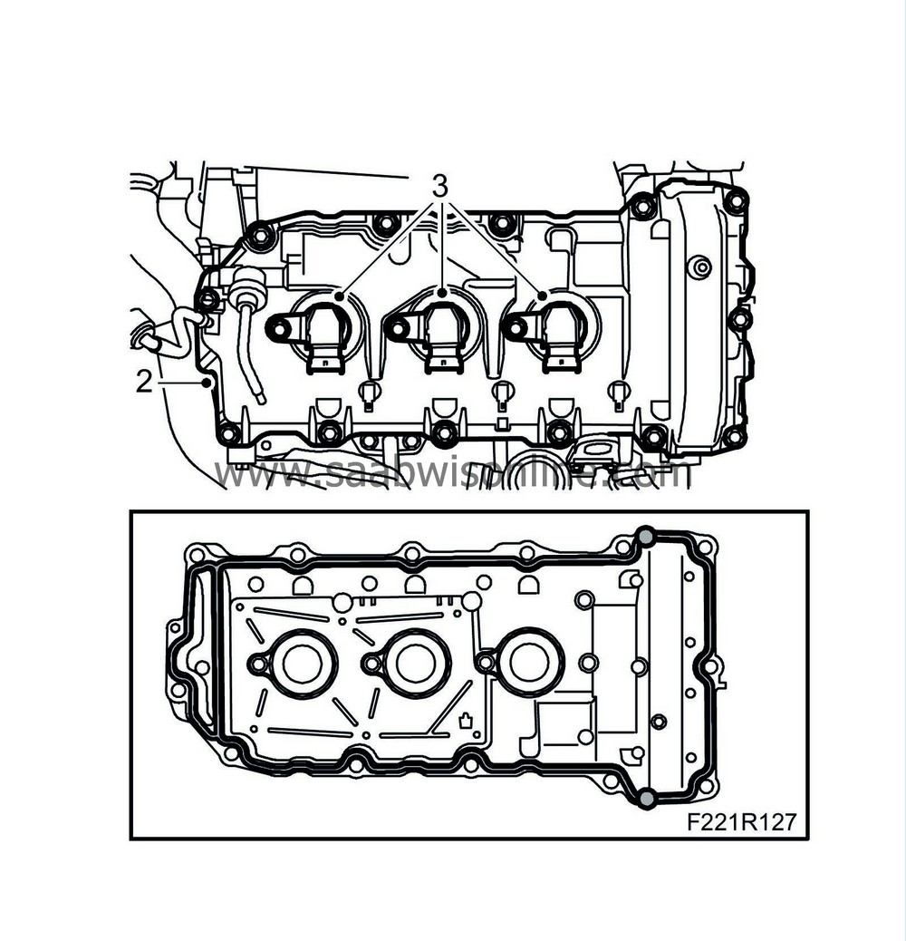
Remove the front camshaft cover.
|
|
41.
|
Remove the gasket and the spark plug hole seals.
|
|
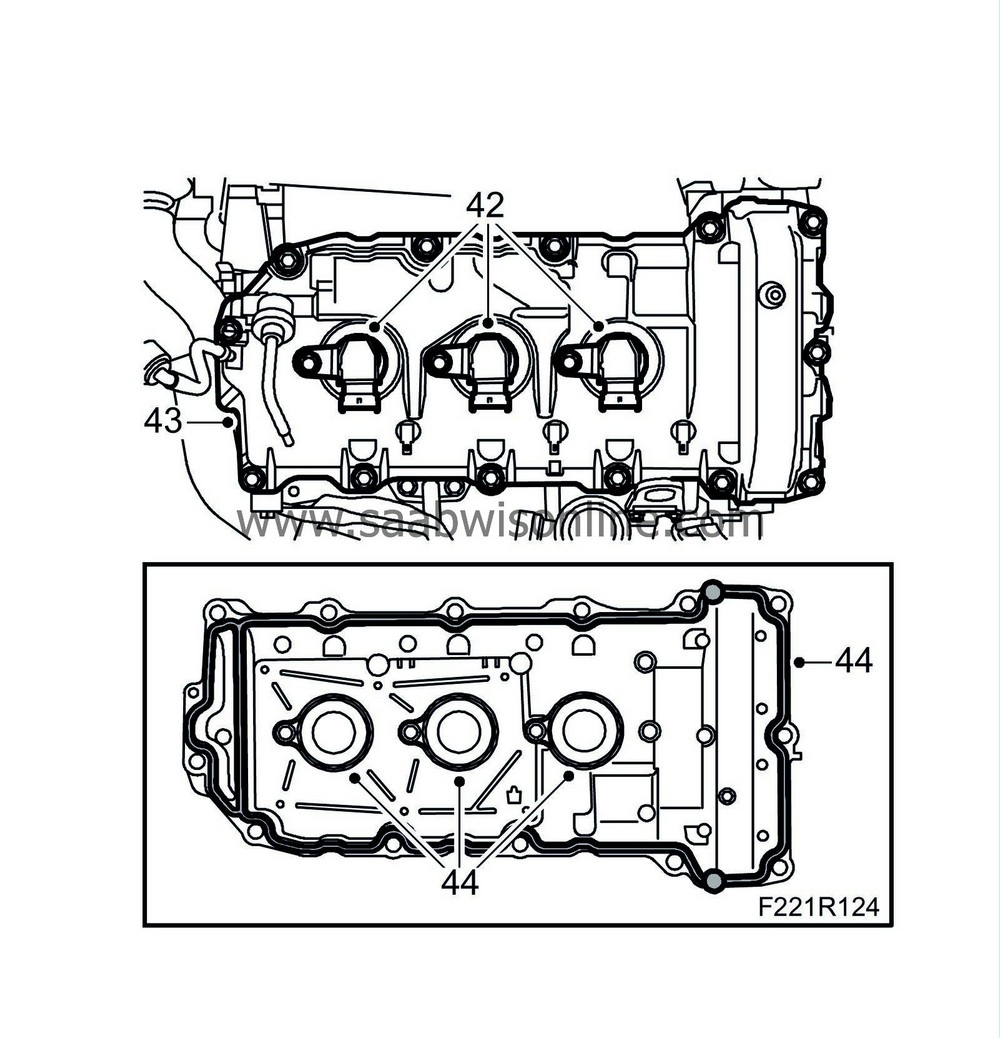
42.
|
Remove ignition coils 1, 3 and 5.
|
|
43.
|
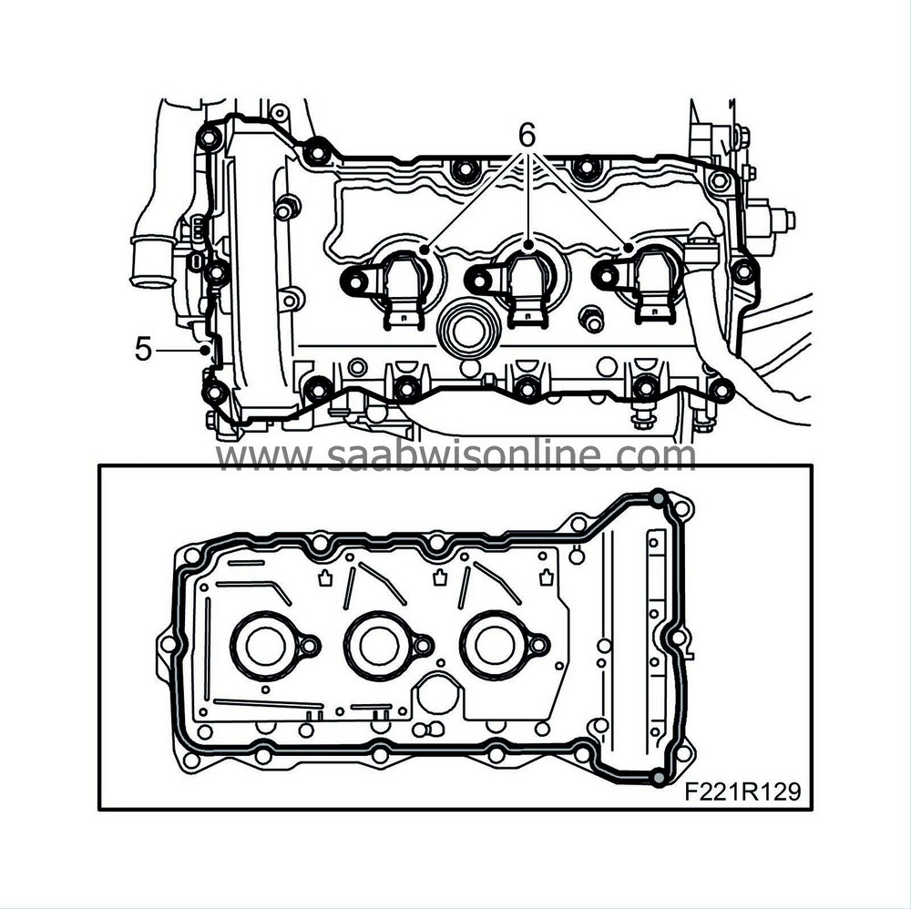
Remove the rear camshaft cover.
|
|
44.
|
Remove the gasket and the spark plug hole seals.
|
|
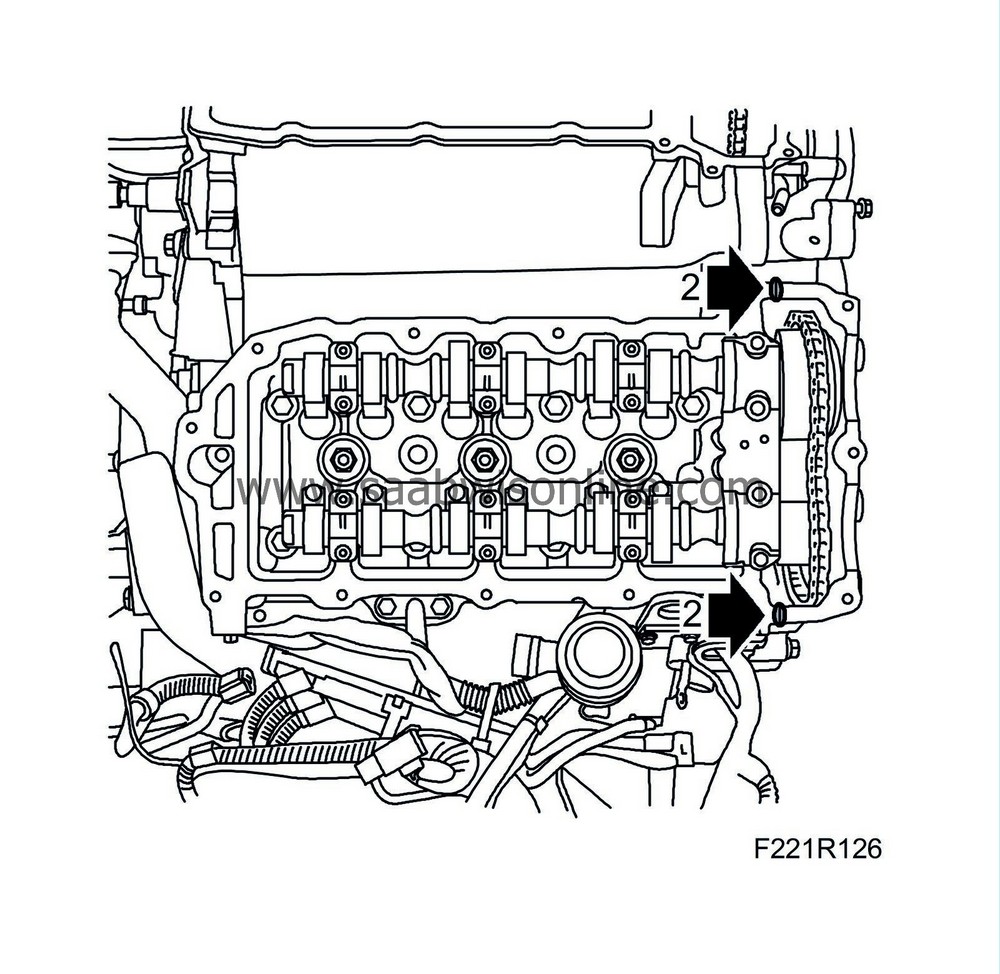
2.
|
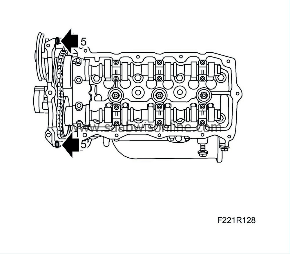
Add a spot of
93 160 951 Flange sealant
on each mating surface between the cylinder head and timing cover as illustrated. Fit the rear camshaft cover.
Tightening torque 10 Nm (7 lbf ft)
|
|
3.
|
Fit ignition coils 1, 3 and 5.
|
|
5.
|
Add a spot of
93 160 951 Flange sealant
on each mating surface between the cylinder head and timing cover as illustrated. Fit the front camshaft cover.
Tightening torque 10 Nm (7 lbf ft)
|
|
6.
|
Fit ignition coils 2, 4 and 6.
|
|
7.
|
Fit the wiring harness in its anchorages.
|
|
8.
|
Fit the cable duct to the timing cover.
|
|
9.
|
Fit the connectors to ignition coils 1, 3 and 5.
|
|
10.
|
Fit the connectors to the front and rear camshaft position sensor plus the connectors to the front and rear camshaft's solenoid valve.
|
|
11.
|
Fit the oil delivery sensor connector and the knock sensor.

|
|
12.
|
Raise the heat shield and fit the coolant temperature sensor connector.
|
|
13.
|
Fit the front ground connections and the connectors of ignition coils 2, 4 and 6.
|
|
14.
|
Lift up the wiring harness so that the fuel pressure sensor is exposed. Fit a new gasket and carefully fit the two intake manifolds as a unit.
Tightening torque 23 Nm (17 lbf ft)

|
|
15.
|
Fit the secondary air valve mounting.
|
|
16.
|
Fit the fuel pressure sensor connector.
|
|
17.
|
Fit the cable in the clip and plug in the throttle body connector.
|
|
18.
|
Fit the crankcase ventilation pipes to the intake manifold.

|
|
19.
|
Attach the brake vacuum hose to the intake manifold and valve.
|
|
20.
|
Attach the connectors of the injectors' wiring harness to the injectors.
|
|
21.
|
Fit the corner bracket to the intake manifold.
|
|
22.
|
Attach the engine vent pipe to the intake manifold.
|
|
23.
|
Fit the front lifting eye.
Tightening torque: 65 Nm (48 lbf ft)

|
|
24.
|
Fit the valve and the front secondary air pipe.
|
|
25.
|
Fit the secondary intake manifold.

|
|
26.
|
Fit the heat shield between the turbocharger and engine.
|
|
27.
|
Fit the upper mounting of the front catalytic converter.
Tightening torque, M10: 42 Nm (31 lbf ft)
|
|
28.
|
Position the turbocharger, being careful not to damage the return oil pipe. Install the turbocharger.
|
|
29.
|
Fit the bolt holding the turbocharger to the bracket.
Tightening torque: 65 Nm (48 lbf ft)
|
|
30.
|
Fit the nuts holding the rear intermediate exhaust pipe to the turbocharger.
Tightening torque 30 Nm (22 lbf ft)
|
Important
|
|
The conical side of the nut should face the centre exhaust pipe.
|
|
|
|
|
31.
|
Fit the coolant pipe's banjo screw to the turbocharger.
Tightening torque 30 Nm (22 lbf ft)
|
|
32.
|
Fit the turbocharger oil return pipe to the turbocharger.
Tightening torque: 14 Nm (10 lbf ft)
|
|
33.
|
Fit the oil delivery pipe's banjo screws to the turbocharger.
Tightening torque, banjo screw: 30 Nm (22 lbf ft)

|
|
34.
|
Fit the bolt and the oil delivery pipe to the engine.
|
|
35.
|
Fit the crankcase ventilation pipe to the turbocharger and fit the vacuum hoses.

|
|
36.
|
Plug in the bypass valve connector.
|
|
37.
|
Fit the return coolant pipe to the turbocharger and heat shield.
Tightening torque, banjo screw: 30 Nm (22 lbf ft)
|
|
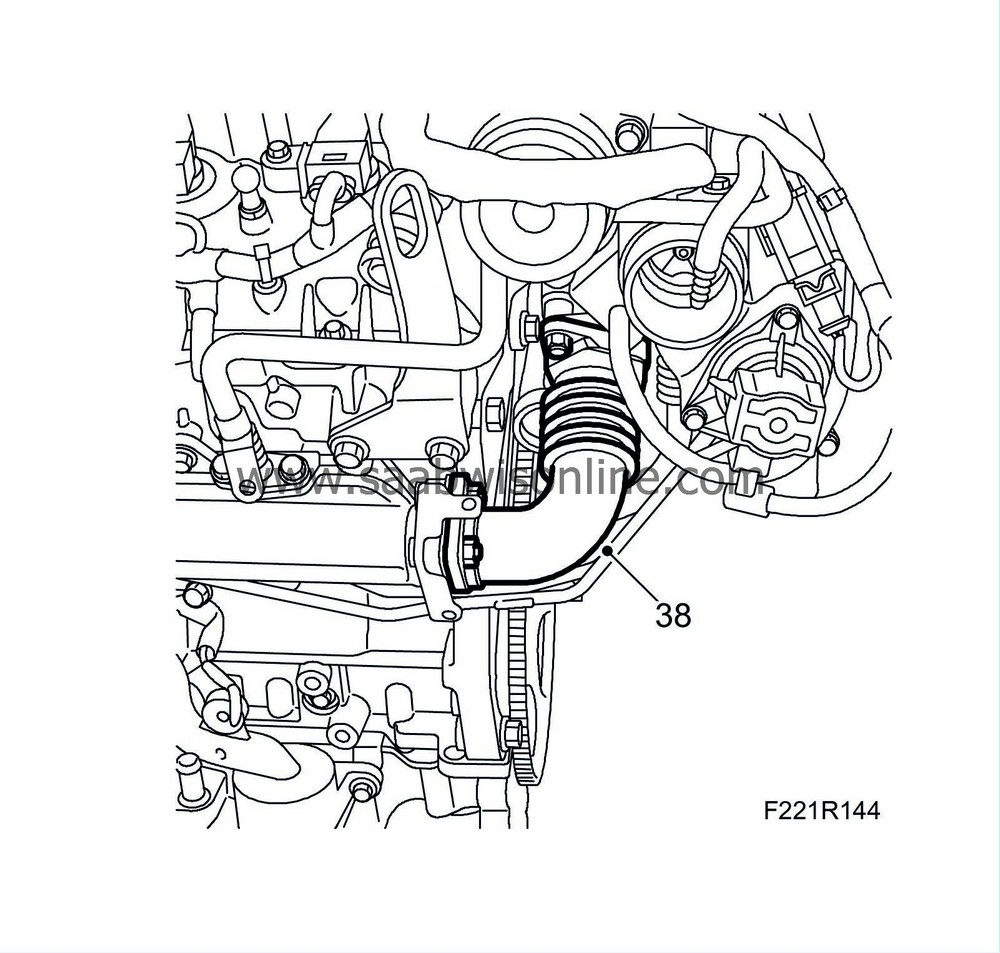
38.
|
Attach the intermediate exhaust pipe to the turbocharger and to the front exhaust manifold. Fit put the nuts in place and then tighten in the order illustrated.
Tightening torque 30 Nm (22 lbf ft)
|
Important
|
|
The conical side of the nut should face the centre exhaust pipe.
|
|
|
|
|
39.
|
Fit the heat shield of the front exhaust manifold.

|
|
40.
|
Fit the O-rings plus the bolt holding the dipstick guide tube.
|
|
41.
|
Remove the engine from the stand and remove the holder from the engine.
|


