Camshafts in situ, front cylinder head, B284 (old version)
|
|
Camshafts in situ, front cylinder head, B284 (old version)
|
|
Important
|
|
Store all removed valve parts in the valve stand 83 93 787.
|
|
|
|
2.
|
Remove the spark plugs.
|
|
3.
|
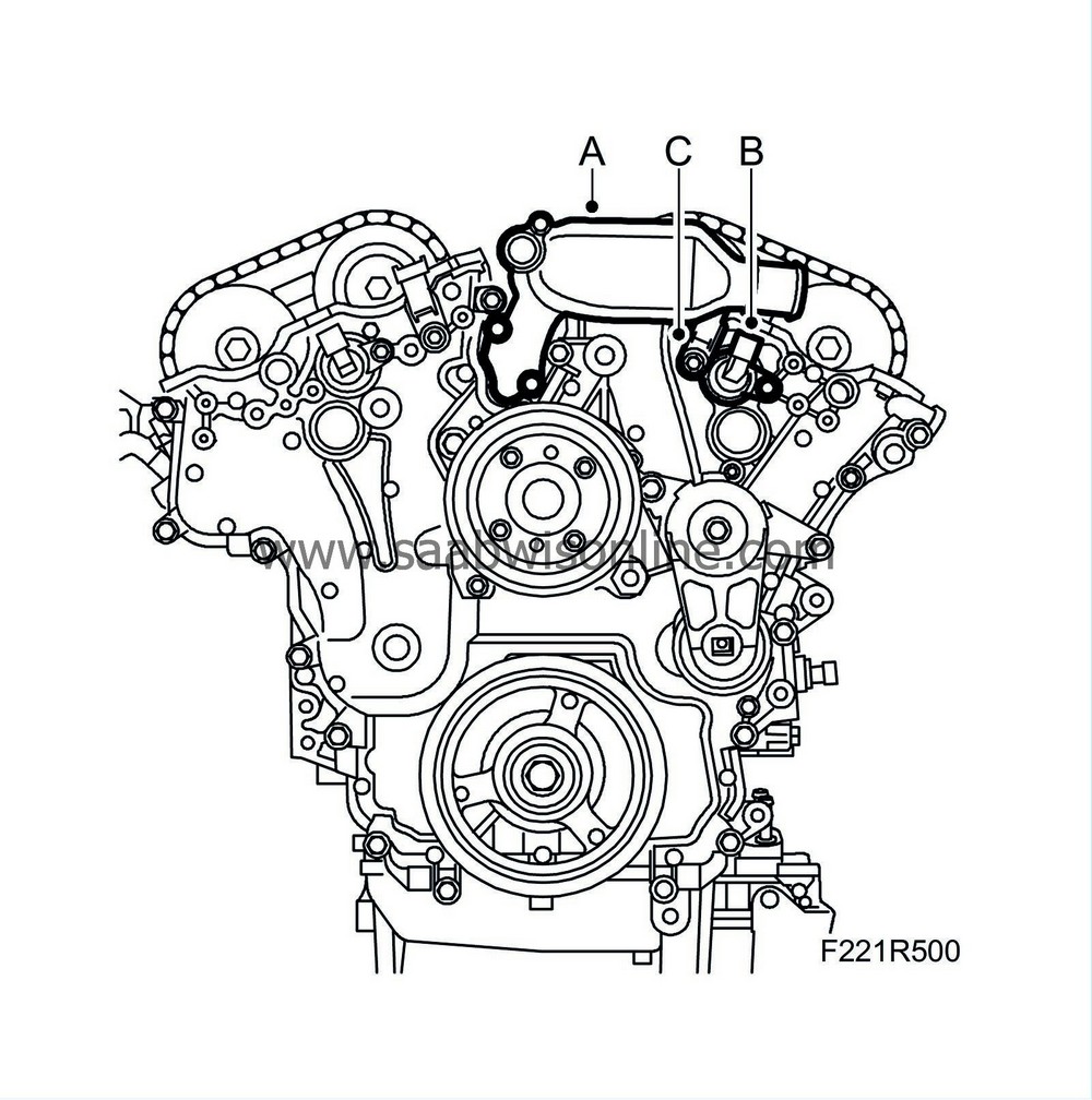
Remove the coolant port (A).
|
|
4.
|
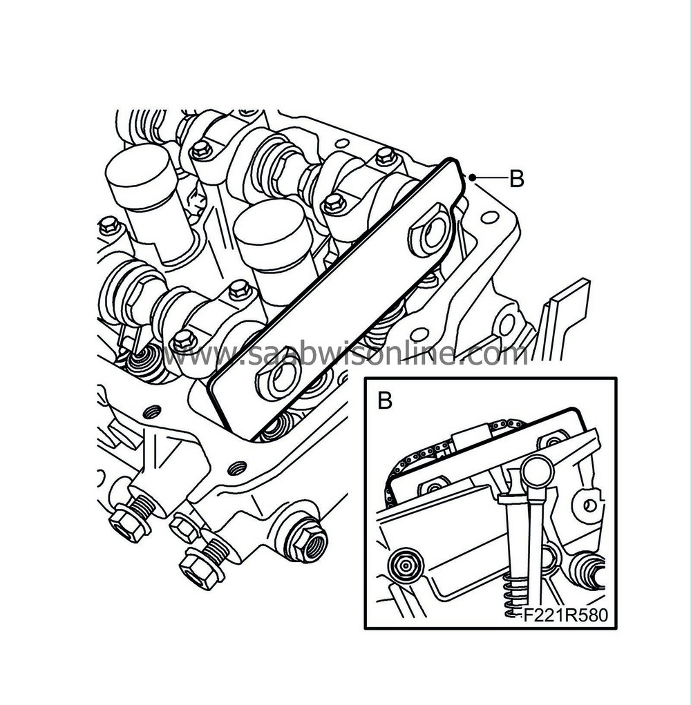
Remove the camshaft solenoid valve (695F) (B).
|
|
5.
|
Remove the camshaft position sensor (555F) (C).
|
|
6.
|
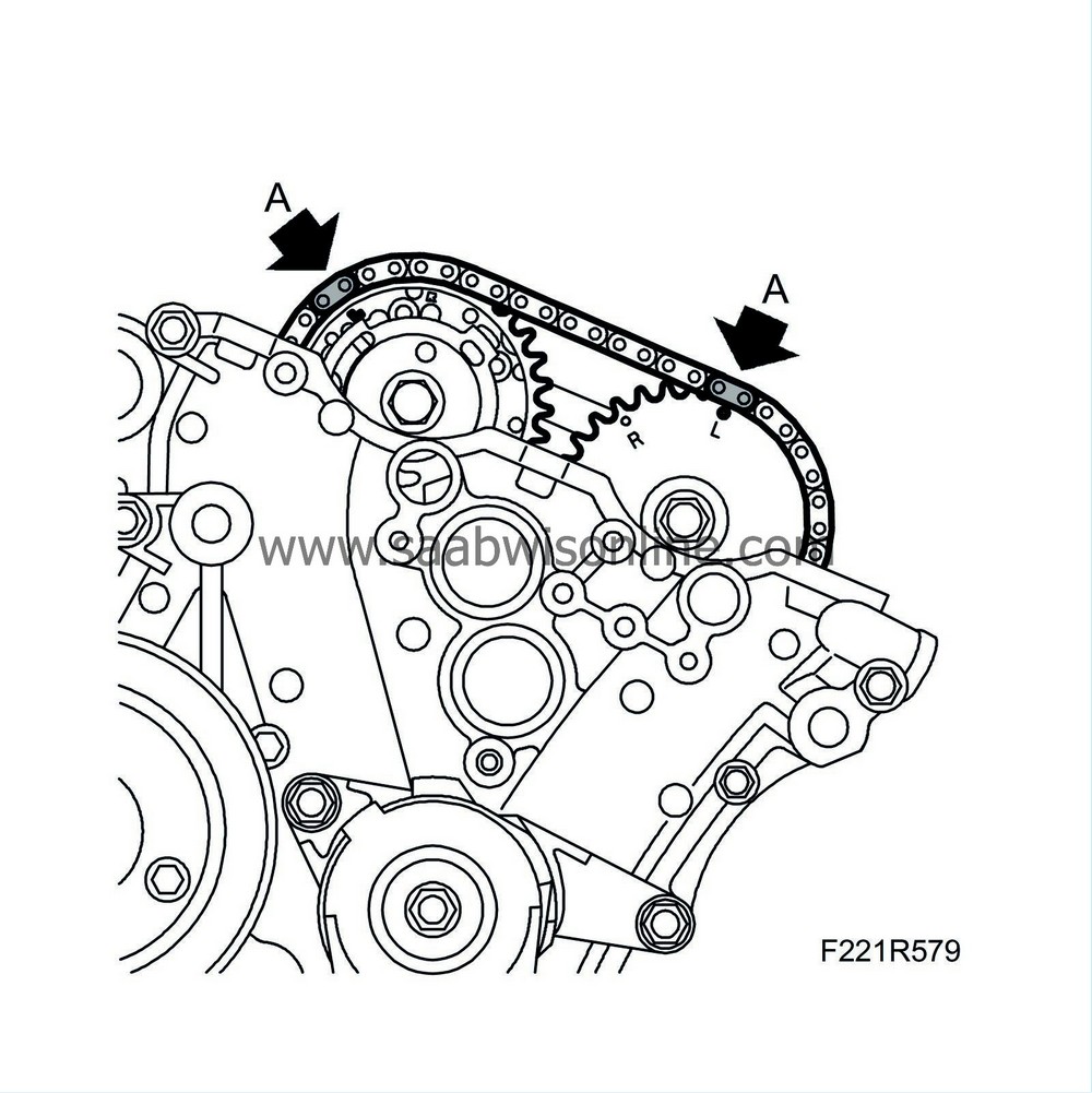
Rotate the crankshaft so that the markings on the camshaft sprockets are visible and the indentations align with the cylinder head (A). Use
EN-46105-1 Adjustment tool
(B) as a gauge (the camshafts are now in their neutral position).
|
|
8.
|
Mark the chain and camshaft sprocket so they can be refitted in the same position.
|
|
9.
|
Loosen the torque on the bolts holding the camshaft sprockets (A). Counterhold using an open spanner on the camshaft flats (do not remove the bolts).
|
|
10.
|
Fit
EN-46108-1 Fixing tool
(B) to the camshaft chain on the intake side. Check that the tool grips the chain firmly.
|
|
11.
|
Fit
EN-46108-2 Fixing tool
(C) to the camshaft chain on the exhaust side. Check that the tool grips the chain firmly.
|
|
12.
|
Tighten
EN-46108 Fixing tool
so that the chain is unloaded.
|
Important
|
|
It is extremely important that tool no. EN-46108 is properly fitted. If the chain is not unloaded when the camshaft sprocket bolts are removed, the automatic chain tensioner is triggered. If this occurs, the timing cover must be removed to adjust the chain tensioner.
|
|
|
|
|
13.
|
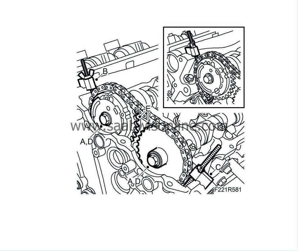
Remove the camshaft sprocket bolts.
|
|
14.
|
Remove the sprockets from the camshafts.
|
|
15.
|
Remove the camshaft bearing caps by loosening the bolts in stages - 1/2 to 1 turn. It is important that removal ends at the bearing cap where the tappets are loaded. Note the markings on the bearing caps when refitting to ensure that they are in the correct spots.

|
|
16.
|
Lift out the camshafts and note the rear marking on the camshafts.
Last letters in the marking:
LI = intake camshaft, front cylinder bank.
LE = exhaust camshaft, front cylinder bank.
|
|
1.
|
Position the camshafts and use
EN-46105 Adjuster tool
to ensure that the camshafts are fitted at the right angle (B). Last letters in the marking:
LI = intake camshaft, front cylinder bank.
LE = exhaust camshaft, front cylinder bank.
|
|
2.
|
Fit the bearing caps as illustrated (A) (markings on caps). Start where the cams point down and load the tappets.
Tightening torque 10 Nm (7 lbf ft)
|
Important
|
|
Tighten the bolts in stages - 1/2 to 1 turn.
|
|
|
|
|
3.
|
Fit the sprockets with chain on the camshafts. Tighten the bolts by hand.
|
|
4.
|
Check that the marks on the chain match the markings on the sprockets.
|
|
7.
|
Tighten the bolts of both camshaft sprockets (C), counterholding with an open spanner on the camshaft flats.
Tightening torque: 65 Nm (48 lbf ft)
|
|
9.
|
Fit the camshaft position sensor (555F) (C) using a new gasket.
Tightening torque 10 Nm (7 lbf ft)
|
|
10.
|
Fit the camshaft solenoid valve (695F) (B) using a new seal.
Tightening torque 10 Nm (7 lbf ft)
|
|
11.
|
Fit the coolant port (A) using a new seal and gasket.
Tightening torque 10 Nm (7 lbf ft)
|


