Main instrument unit, MIU (540)
|
|
Main instrument unit, MIU (540)
|
The principal use of the main instrument unit is to display:
|
2.
|
Odometer and trip meter reading, text messages and symbols
|
|
7.
|
Warning and indicator lights
|
The main instrument unit calculates the following:
|
2.
|
Sums up and stores driven distance
|
The main instrument unit contains a circuit board and microprocessor with clock, RAM memory and programmable ROM.
The gauge needles are each driven by individual stepper motors and all scales, needles, indicators and the display are illuminated with LEDs. The display and a few indicators, e.g. main beam, are dimmed according to the ambient light in daylight, which is controlled by MIU. In the dark, the driver must adjust all illumination (scales, display and some indicators) using the brightness controls on the switch panel (737a).
There are 6 basic types of instrument available depending on engine and market:
|
•
|
Tachometer, petrol, 0-7000 rpm
|
|
•
|
Tachometer, diesel, 0-6000 rpm
|
|
•
|
Speedometer, mph and km/h
|
|
•
|
Without turbo boost gauge
|
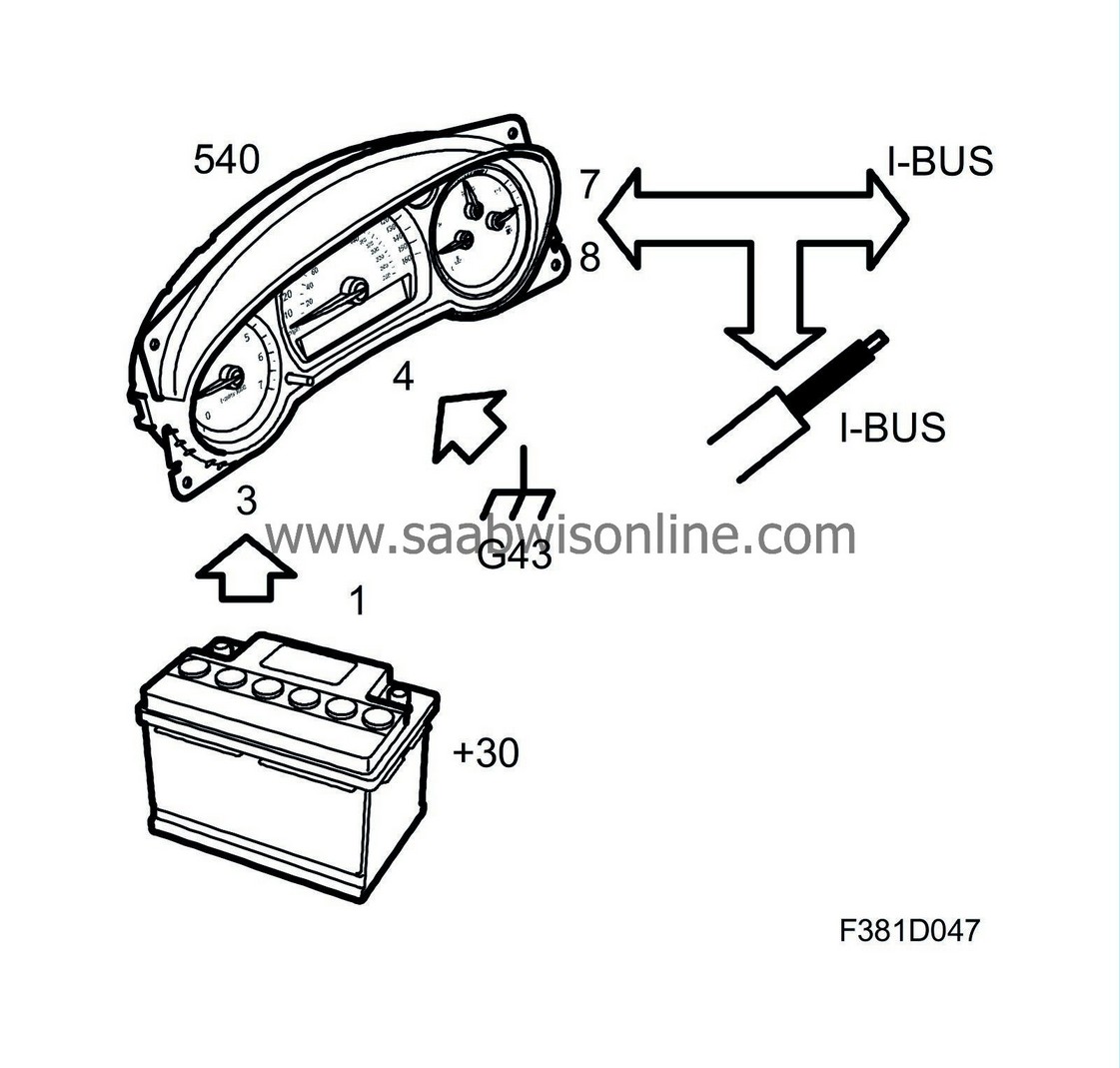
The main instrument unit lamps are turned on and the gauges activated via bus messages from other control modules on the I-bus except the Check Engine lamp, which the engine control module turns on by grounding a pin on the main instrument unit.
When a message is displayed in SID it is indicated with an acoustic signal in the speaker which is integrated in the MIU. If several messages are displayed then only the first message is indicated with an acoustic signal. The MIU is the controller for acoustic warning and indicator signals and it handles signal prioritisation. The MIU receives a bus message and in turn activates the speaker in the MIU.
For a general description of the car's control modules, see
Control Modules, general description
.
|
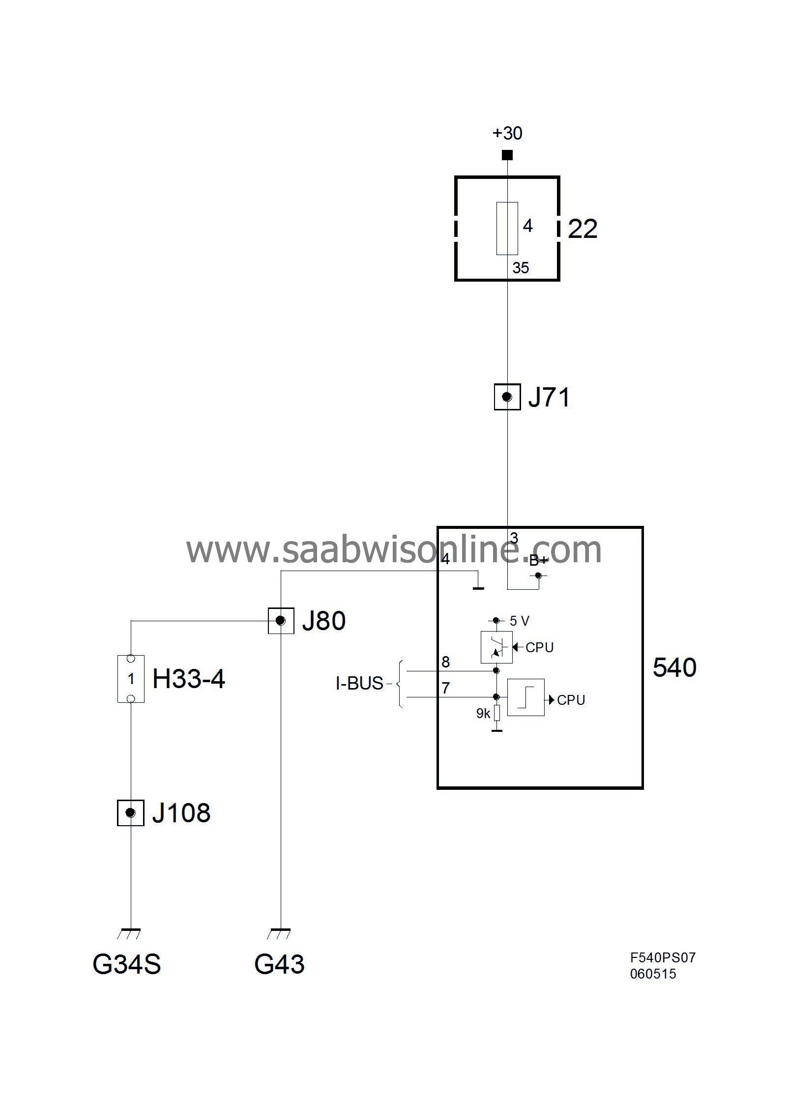
Power supply, ground and bus communication
|
Pin No.
|
Signal type
|
Description
|
|
1
|
Input signal
|
ECM turns on the Check Engine lamp by grounding the pin.
|
|
2
|
+15
|
Switch panel (737a) illuminates the lamp for passenger seat belt when it is not used.
|
|
3
|
+30
|
From instrument panel main fuse box (22) pin 35 via fuse 4.
|
|
4
|
Ground
|
Grounding points G43 and G34.
|
|
5
|
Input signal
|
Regulated panel lighting from switch panel (737a). Signal via BCM.
|
|
6
|
Input signal
|
Night Panel off/on. Regulated via switch panel (737a).
|
|
7
|
I-bus
|
|
|
8
|
I-bus
|
|
Check Engine, T8, ME9 and EDC16
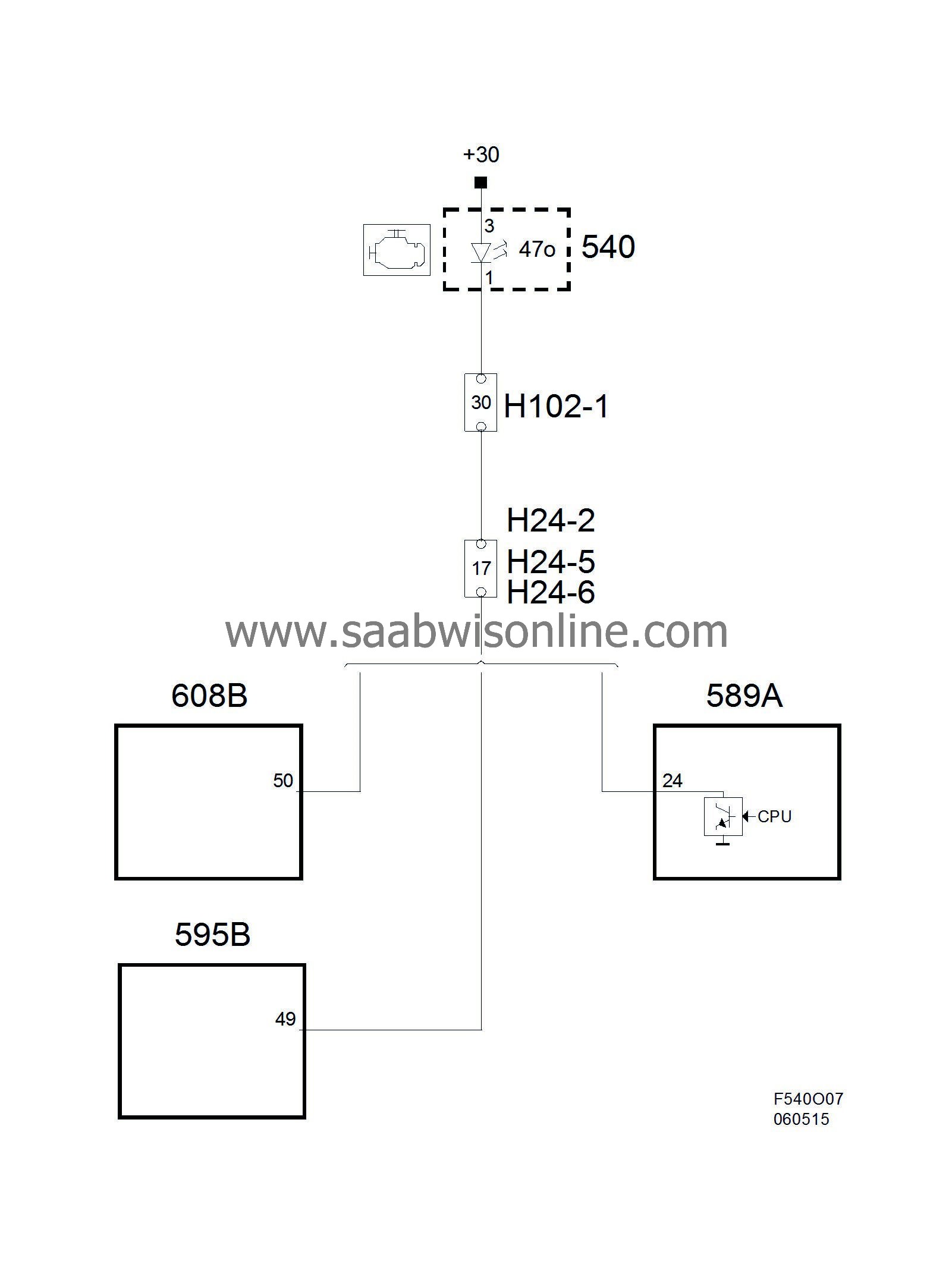
Check Engine, Simtec

Power supply and ground
When the ignition is turned ON, the instrument will perform a lamp check and turn on the display under the speedometer. It will also light up the graduations if the cabin lighting is dim and the needles will rise from their rest positions.
CIM wakes up the main instrument unit when the key is inserted in the ignition switch by briefly applying B+ to the I-bus lead.
Communication can also be initiated when the key is removed from the ignition switch. This is done, for example, when the main beam signal is activated.
Another method of waking the main instrument unit when the ignition is OFF is to press the reset button. This will turn on the display and show the trip and odometer readings for 20 seconds, bus communication will not be initiated.


