PRE-RELEASE
Brake lights, detailed description, 5D
| Brake lights, detailed description, 5D |
The brake lights come on when the brake pedal is depressed. The Rear Electrical Centre (REC) monitors the brake light circuits and sends error messages on the bus if there is a fault. The car has brake lights situated in the right and left-hand light clusters as well as a high-level brake light in the spoiler. The car's brake lights comprise only LEDs.

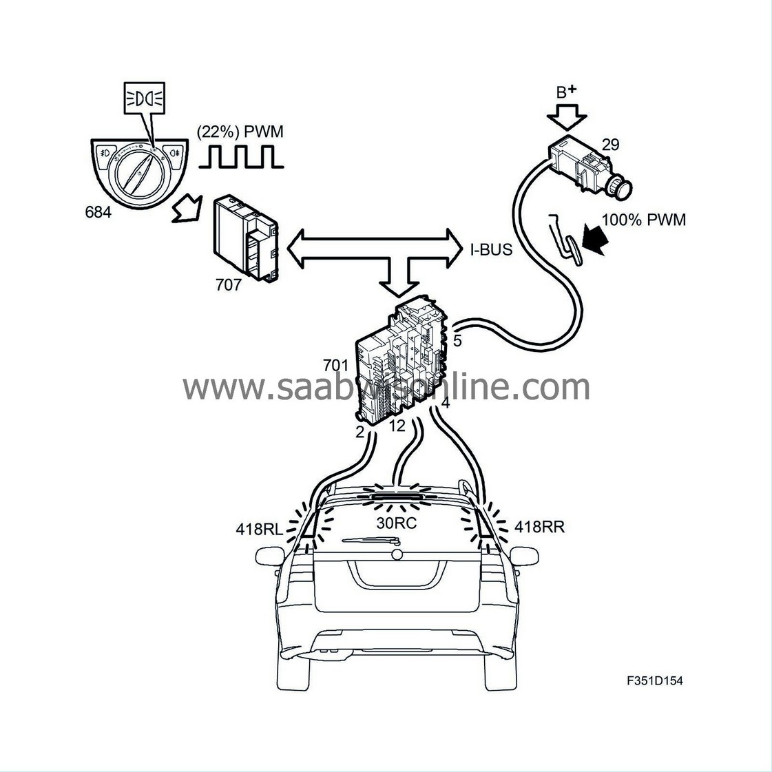
When the parking lights are on, the light clusters are supplied with a B+ voltage on pin 6. In each light cluster there are electronics that convert the B+ voltage to a PWM voltage of a suitable magnitude to reduce the light intensity.
To turn on the brake lights, B+ is fed to the light cluster pin 1, which lights the LEDs at full intensity. A total of 19 LEDs come on when the brake light is activated, which is four LEDs more than the 15 used for the parking light. A message will be displayed on SID of there is a break in the circuit. Note that REC cannot detect the failure of individual LEDs.
Brake lights via lead (normal function)
Depressing the brake pedal will affect the brake light switch (29). The brake light switch (29) is supplied with +30 on pin 1, when the switch closes B+ will be applied to pin 2. From the brake light switch pin 2, voltage is supplied to the engine control module and to REC (701) pin 5 (B2-D). Irrespective of the ignition switch position, REC feeds B+ from pin 2 (R-D) to the light cluster (30/418RL) pin 1 for the left-hand brake light and from pin 4 (R-D) to the light cluster (30/418RR) pin 1 for the right-hand brake light plus from pin 12 (T-B) to the high level brake light (30RC) pin 1. The light cluster (418RL/RR) pin 3 is grounded to grounding point G15. The high level brake light (30RC) pin 2 is grounded to grounding point G29.
Brake lights via bus message (substitute function)
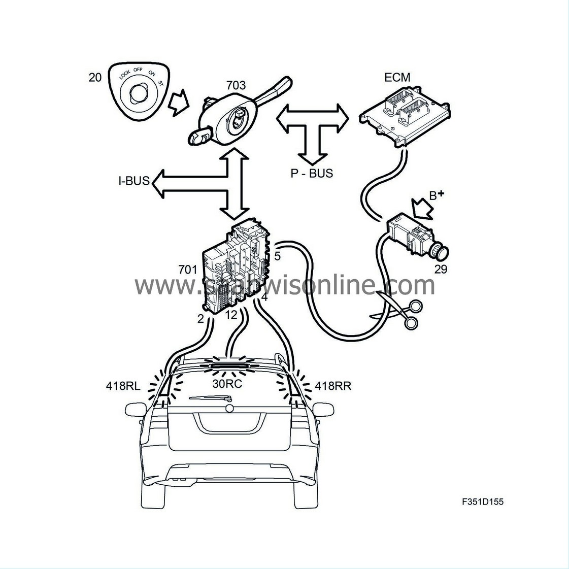
This function replaces the lead between the brake light switch (29) and REC (701) in the event of a break along the lead. The function is only active when the ignition switch is in the ON or START position.
The brake pedal switch (134) is also connected to the ECM. The engine management system uses this input for its own functions e.g. cruise control, but also transmits input status on the bus, as a bus message "Brake pedal switch, active" ON. This bus message is only used by the REC when the ignition is in the ON or START position, as replacement for a missing signal on its input for the brake light switch (29). The REC supplies B+, from pin 2 (R-D) to the light cluster's (30/418RL) pin 1 for left-hand brake light and from pin 4 (R-D) to the light cluster's (30/418RR) pin 1 for right-hand brake light, as well as from pin 12 (T-B) to the high-level brake light (30 RC) pin 1. The light clusters' (418RL/RR) pin 3 is grounded in grounding point G15. The high-level brake light (30RC) pin 2 is grounded in grounding point G29.
Filament monitor
If several LEDs fail, REC (701) will detect the low current in the circuit. REC sends a bus message "Left brake light not working" ON or "Right brake light not working" ON, depending on the circuit that is at fault. This bus message is used by SID to show a warning message on the display. Note that REC cannot detect the failure of individual LEDs.
If there is a break in the circuit of the high-level brake light, REC (701) detects that current in the circuit is low. REC sends the bus message "Centre brake light not working ON". This bus message is used by SID, which shows a warning message in the display.
| Note | ||
|
REC (701) cannot determine whether individual LEDs in the brake light have failed. |


