PRE-RELEASE
Ignition system
| Ignition system |
| Ignition system, general |
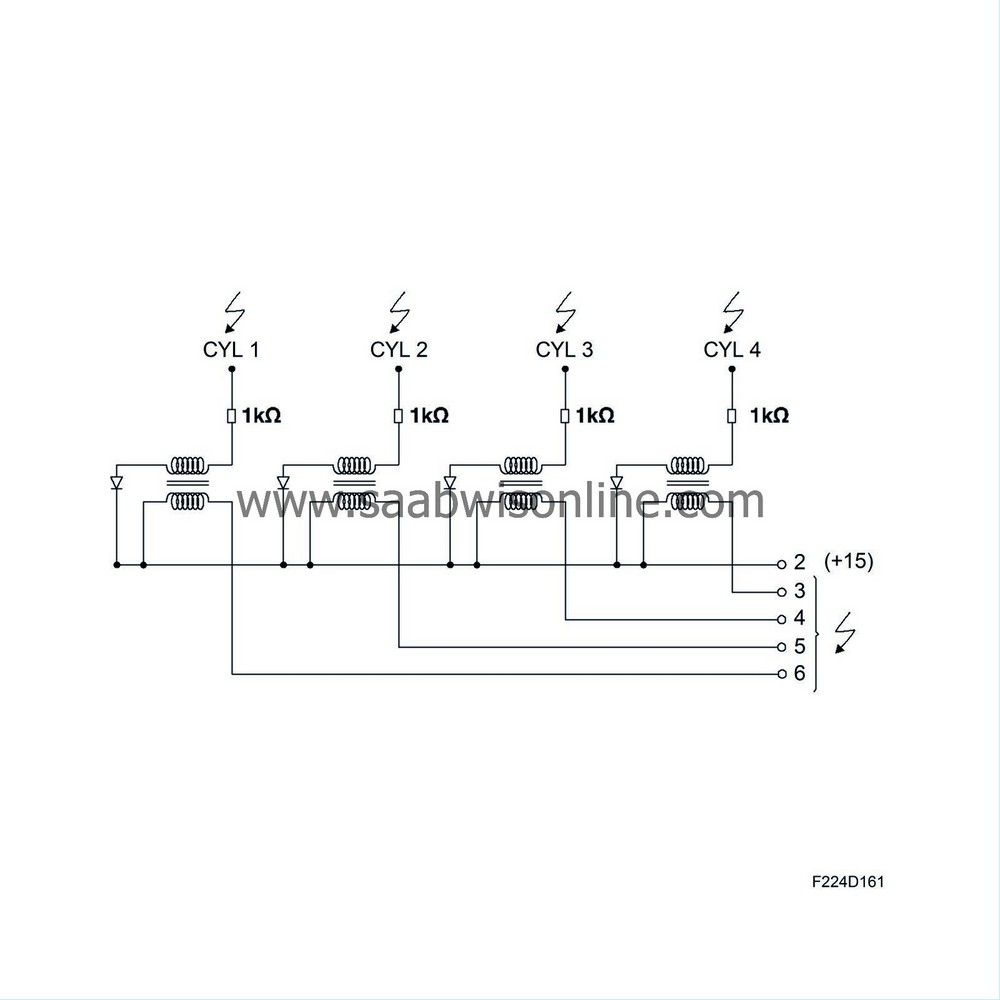
The ignition system is used to generate the igniting spark. It comprises four inductive ignition coils, one for each cylinder, integrated into one unit. This unit cannot be repaired; if a fault occurs in one ignition oil, the entire unit must be changed. The ignition system receives four ignition trigger signals from ECM.
| Ignition |
The ignition system comprises four inductive ignition coils, one for each cylinder, integrated into one unit. The ignition coils are supplied with B+ on pin 2 from the main relay (229).


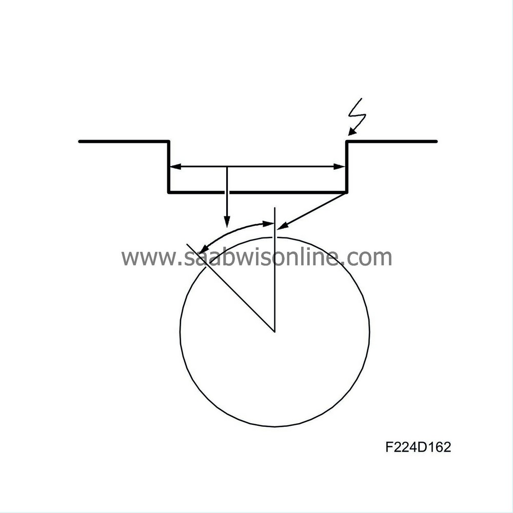
A magnetic field is then gradually built up inside the ignition oil and when the spark is to be formed, ECM will stop grounding the primary side. The magnetic field will then collapse and as a result a high voltage will be induced (built up) across the ignition oil secondary winding.
The spark is consequently formed when the current ceases and this time is the same as the current ignition timing. So ECM determines the charging time (camshaft angle) and the ignition timing. The camshaft angle is dependent on the system voltage in the car and the ignition timing mainly on the engine load and speed.
The voltage on the secondary side is much higher as the number of windings of copper wire is much greater. The voltage on the secondary side is built up until there is a breakdown across the spark plug gap, which happens at about 5-30 kV, depending on the conditions prevailing in the cylinder. The high pressure that occurs under high engine loads requires a higher voltage than under lighter conditions.
The ignition coils can generate voltages of up to 40 kV. There are four ignition trigger lines connected to the ignition system from the ECM as follows:
| • |
The ignition coil pin 6 for cylinder 1 is connected to ECM pin 15, 47(A)
|
|
| • |
The ignition coil pin 5 for cylinder 2 is connected to ECM pin 31, 63(A)
|
|
| • |
The ignition coil pin 4 for cylinder 3 is connected to ECM pin 32, 64(A)
|
|
| • |
The ignition coil pin 3 for cylinder 4 is connected to ECM pin 16, 48(A)
|
|
| Charging time, general |
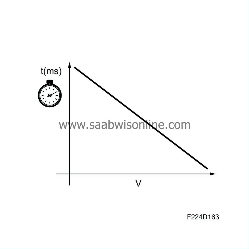
The ignition coil charging time depends on the system voltage. This is so that the right energy/voltage is obtained in the spark irrespective of the battery voltage.

| Principle, voltage dependence |
A relatively low battery voltage requires a longer charging time to obtain the same spark energy/voltage.
Conversely, a relatively high battery voltage gives a shorter charging time in order to prevent unnecessary heating of the ignition coils and to reduce wear on the spark plug electrodes.


