Power unit, fitting, Z19DT/DTH
|
|
Power unit, fitting, Z19DT/DTH
|
 Warning
|
|
A large number of hoses, cables, etc., are secured with cable ties. After tightening, the ties are cut off and leave more or less sharp edges at the fastening point. Watch out for the risk of cuts due to these sharp ends on the cable ties!
|
|
|
|
|
|
|
1.
|
Position the trolley lift with power unit and adjust its position in relation to the body. Use 82 93 102 Extension, 500 mm, 3/8 square, through the holes in the subframe to the attachments in the body. See
Centring tool, engine and subframe
|
|
2.
|
Lift up the powertrain until the left drive shaft universal joint is level with the wheel hub and insert the drive shaft into the hub. Make sure nothing gets caught or damaged.
|
|
3.
|
Lift a little higher and position the lower swivel joints to the steering swivel members. If necessary, adjust the trolley lift screws to provide even contact with the body. Check that the guide pins are positioned correctly relative the reference holes in the body.
|
|
4.
|
Position the bolts and screw them through the subframe into the body.
|
|
5.
|
Raise the engine completely and tighten the subframe bolts.
Tightening torque, subframe: 75 Nm + 135° (55 lbf ft +135°)
Tightening torque, stay: 90 Nm + 45° (66 lbf ft +45°)
|
|
6.
|
Lower the trolley lift and move it out of the way.
|
|
7.
|
Lower the car.
|
|
8.
|
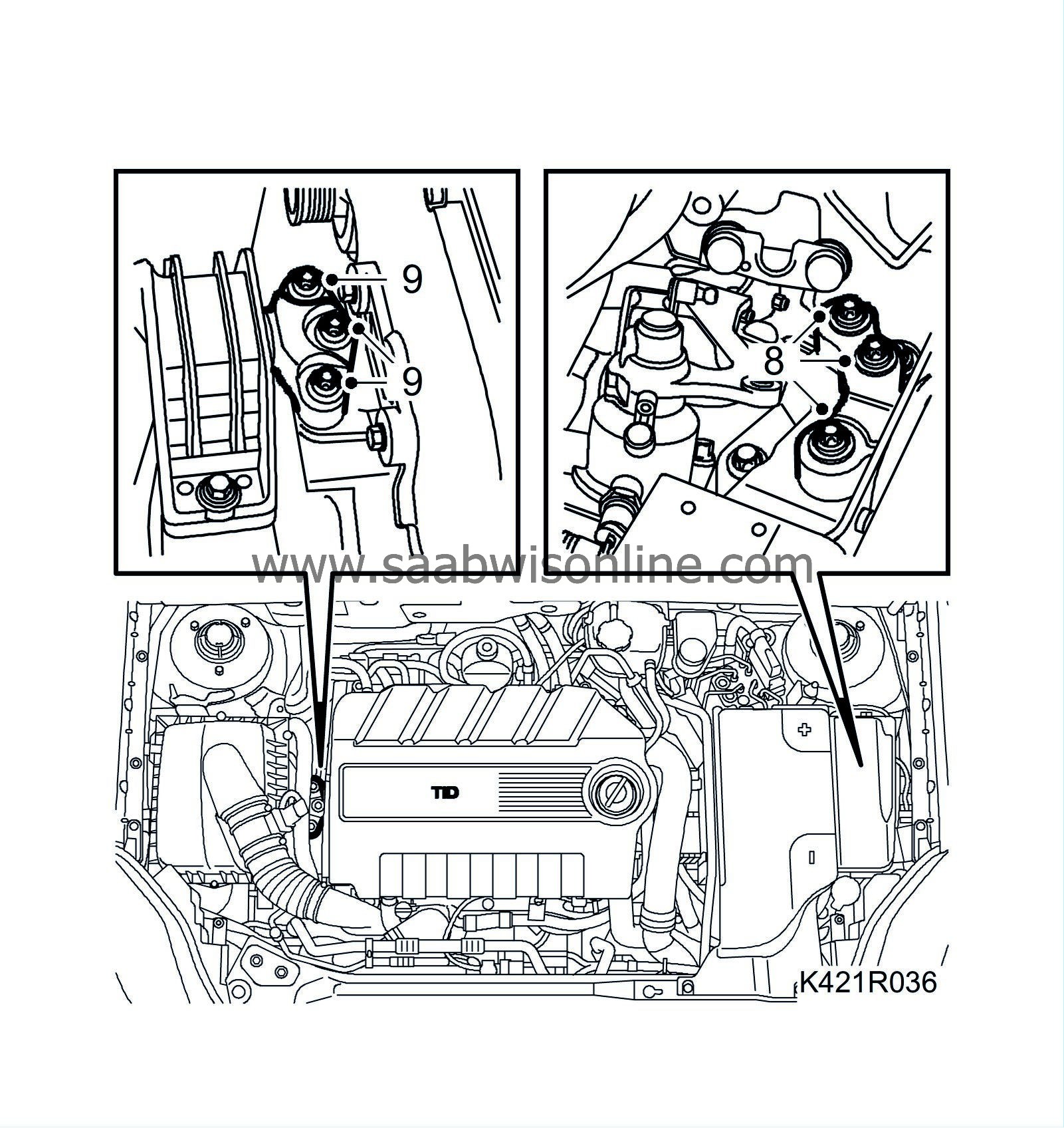
Fit the left engine mounting.
Tightening torque: 70 Nm +45° (52 lbf ft +45°)
|
|
9.
|
Fit the right engine mounting.
Tightening torque: 70 Nm +60° (52 lbf ft +60°)
|
|
11.
|
Remove the centring fixture.
|
|
12.
|
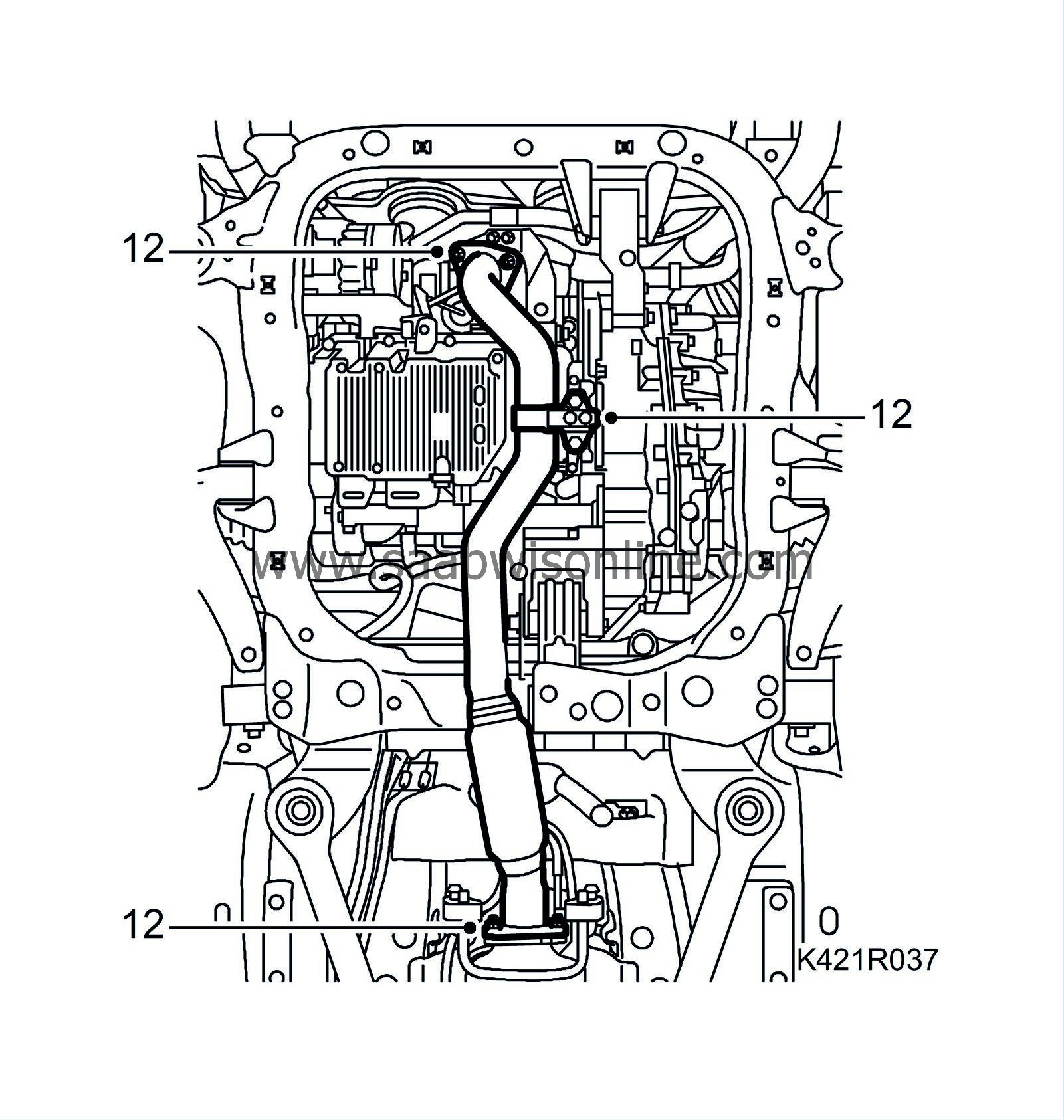
Fit the front exhaust pipe.
|
|
13.
|
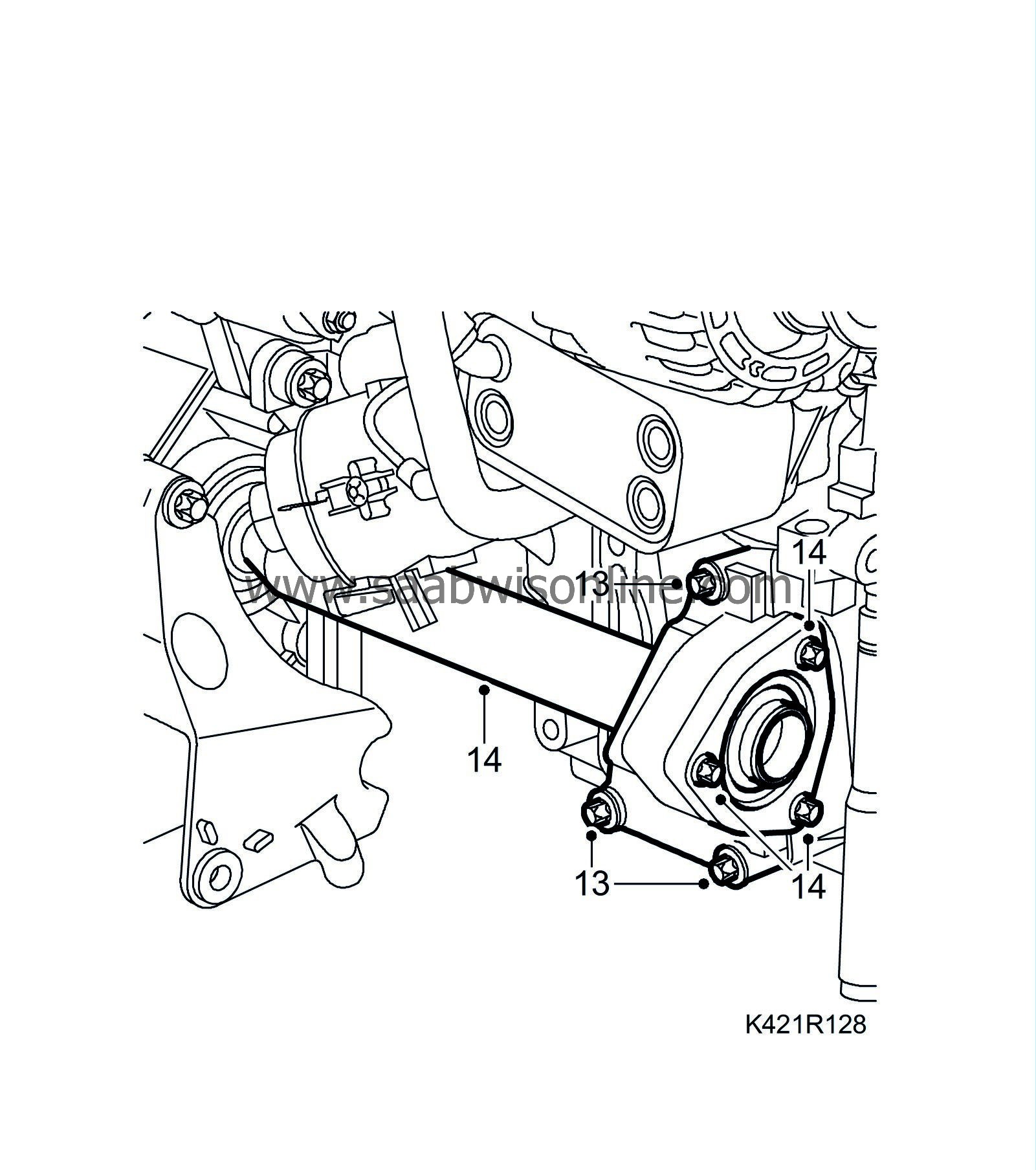
Fit the intermediate shaft bracket.
Tightening torque 24 Nm (18 lbf ft).
|
|
14.
|
Fit the intermediate shaft and the outer drive shaft.
|
|
15.
|
Tighten the bolts on the lower swivel joints.
Tightening torque 50 Nm (37 lbf ft)
|
Important
|
|
Ensure that the steering knuckle stub is visible on the top of the steering knuckle housing before the bolt is fitted.
|
|
|
|
|
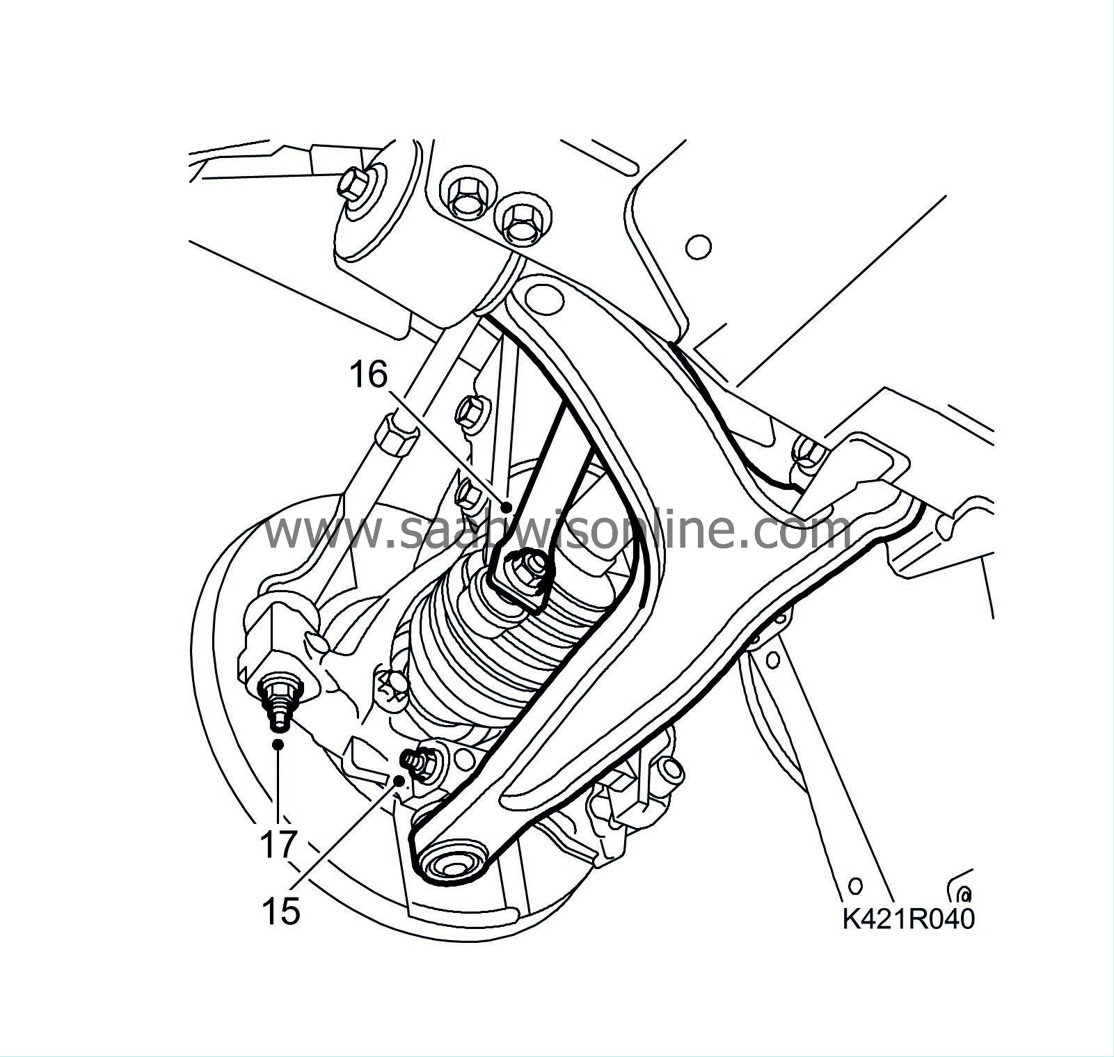
16.
|
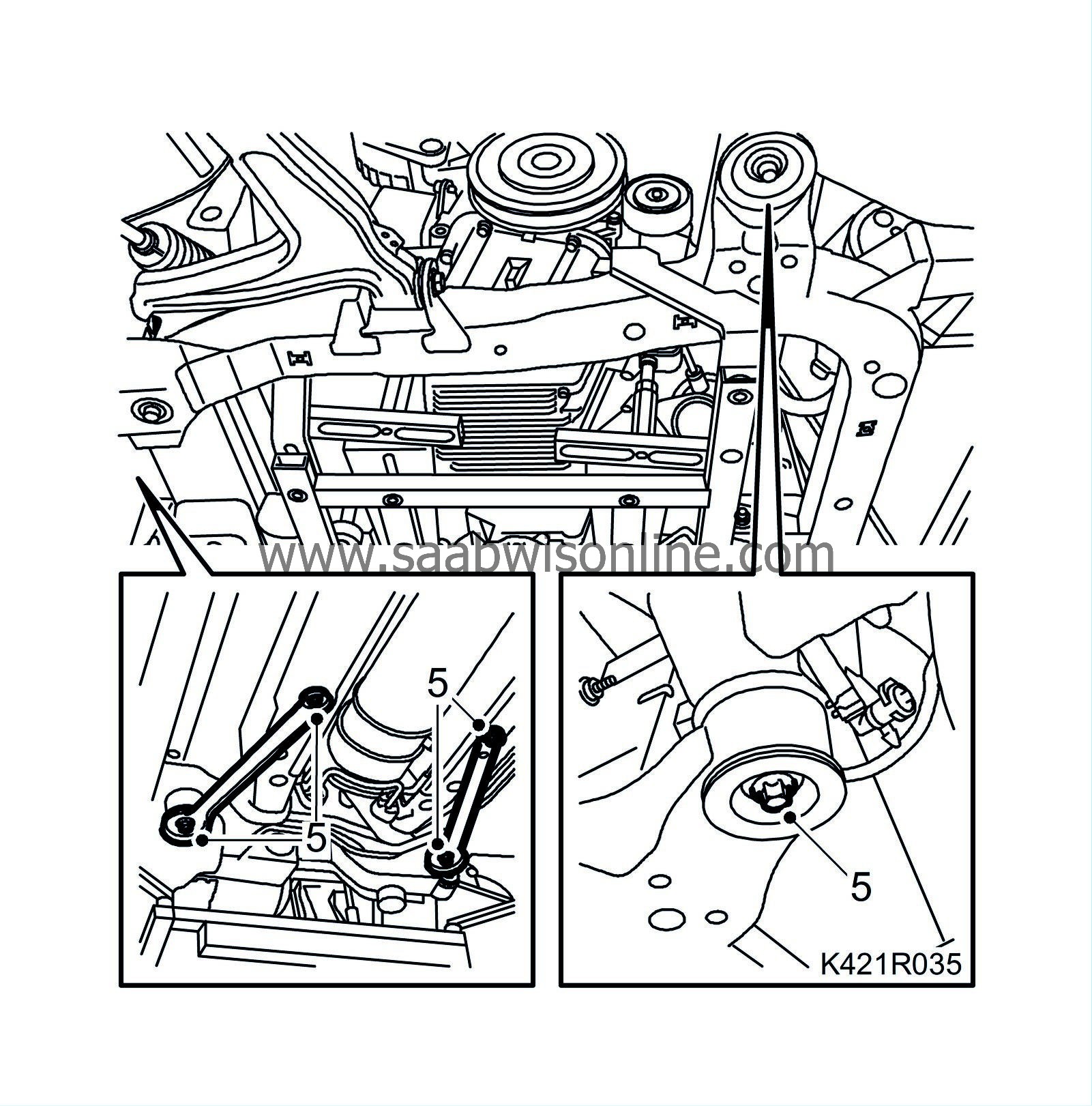
Position the lower anti-roll bar links and tighten them while gripping the flats with a thin spanner.
Tightening torque 64 Nm (47 lbf ft)
|
|
17.
|
Position the outboard steering links and tighten them.
Tightening torque 35 Nm (26 lbf ft)
|
|
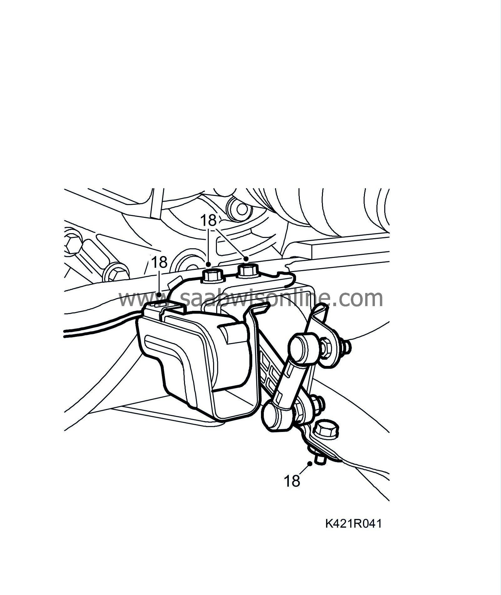
18.
|
Option:
Fit the angle sensor bracket to the suspension arm. Secure the cable to the subframe and plug in the connector of the headlamps angle sensor.
|
|
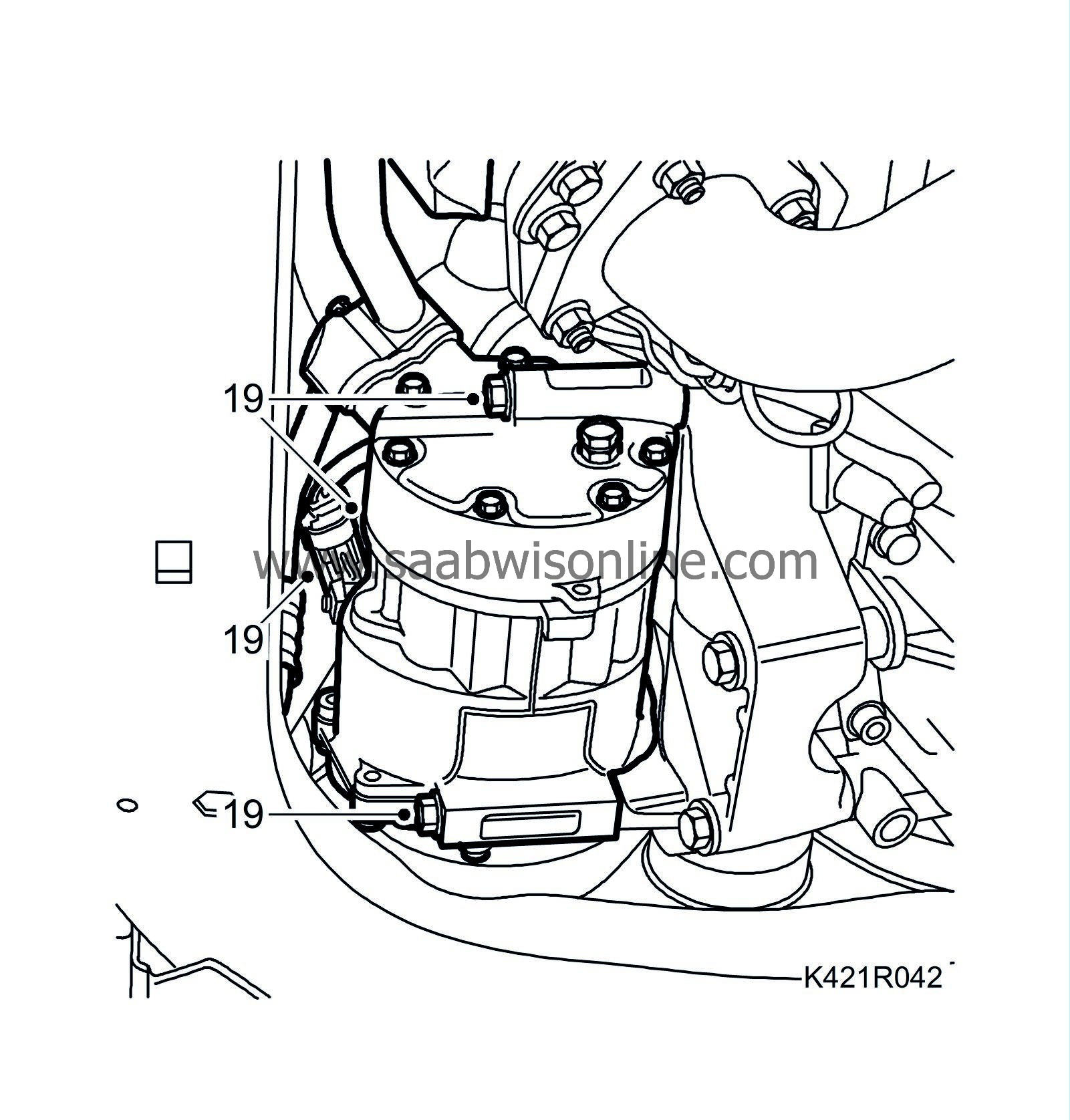
19.
|
Fit the A/C compressor retaining bolts and plug in the A/C compressor connector.
|
|
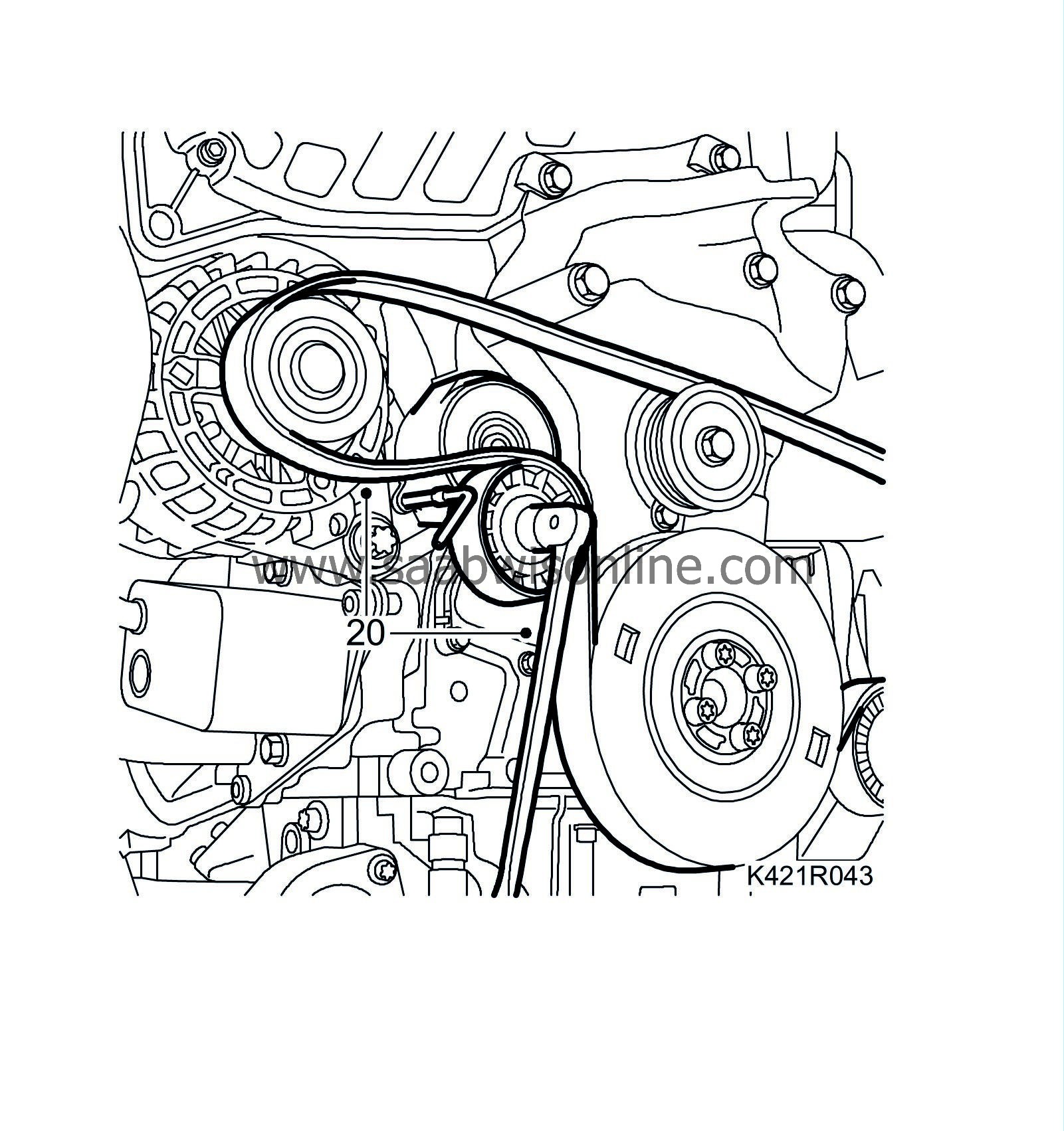
20.
|
Fit the multigroove belt so that it follows the marked direction of rotation.
|
|
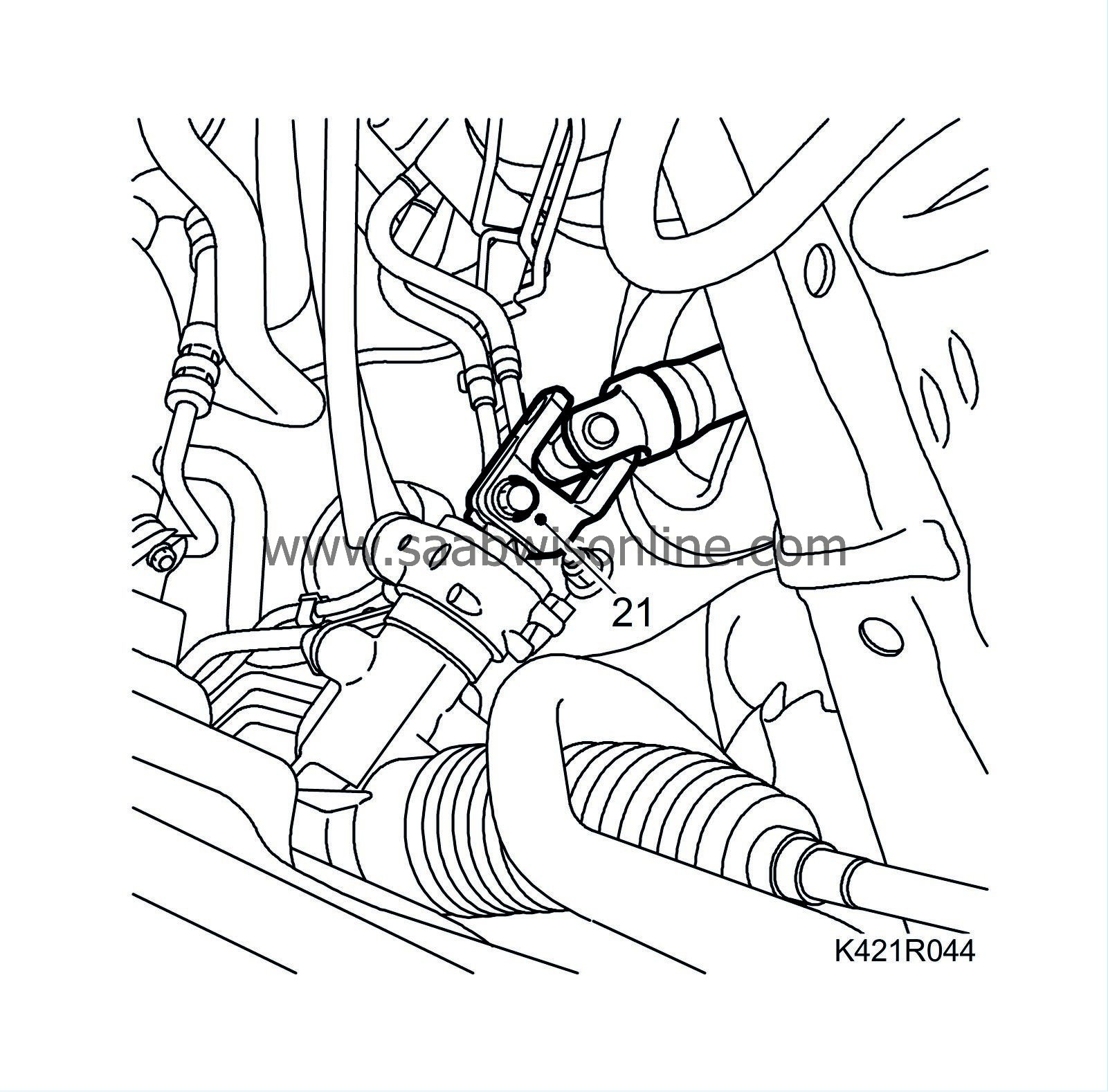
21.
|
Connect the steering shaft to the steering gear. Use Thread locking adhesive, Loctite 242 on the bolt.
Tightening torque: 30 Nm (19 lbf ft)
|
|
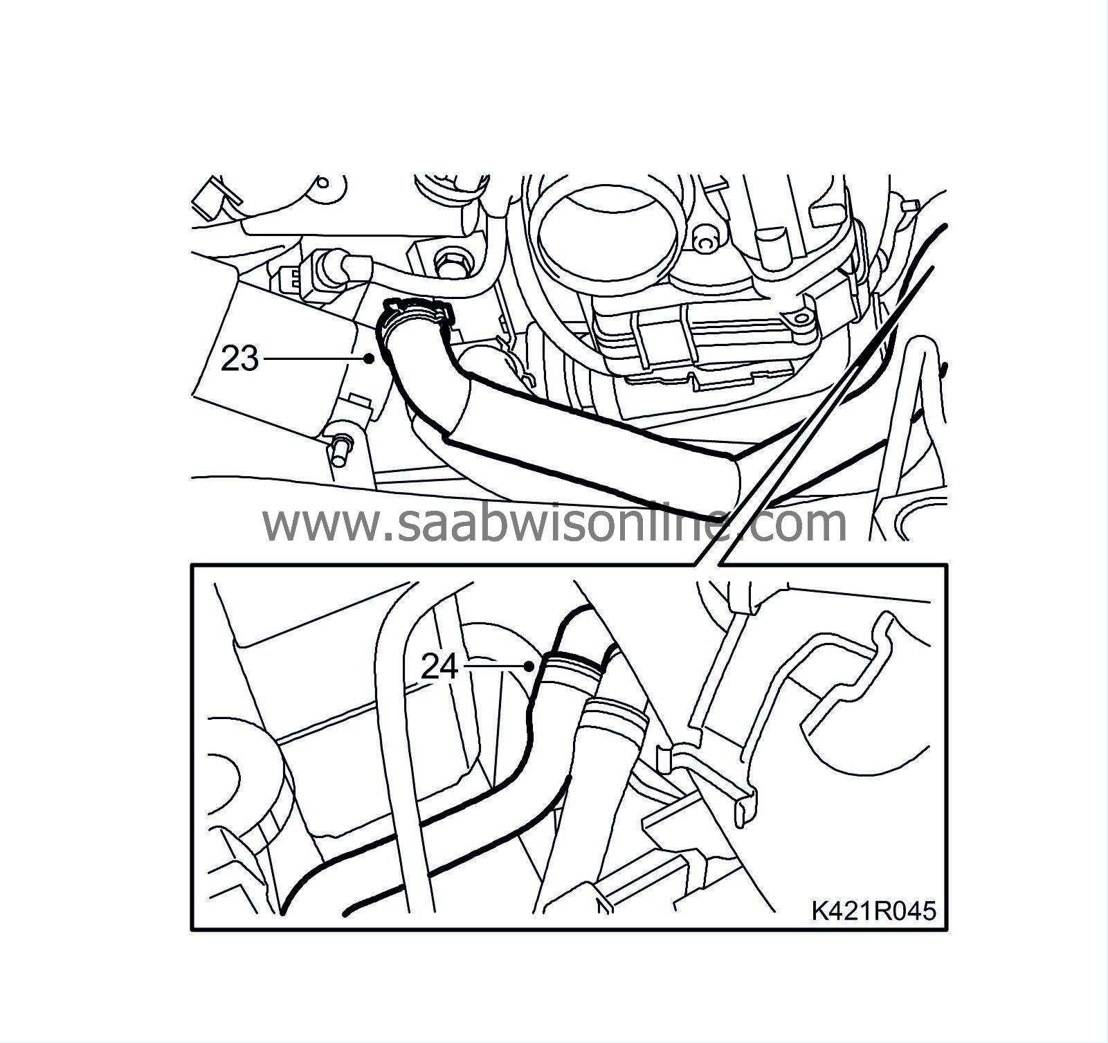
23.
|
Option:
Attach the coolant hose that runs to the parking heater on the thermostat housing.
|
|
24.
|
Connect the quick coupling on the right-hand coolant hose and secure the retaining clip on the bulkhead.
|
|
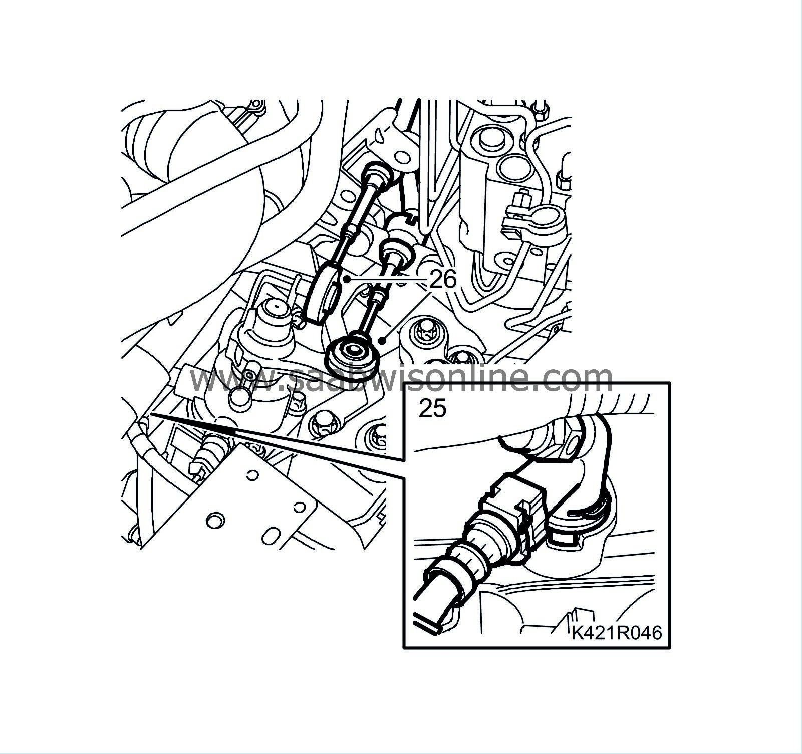
25.
|
Man:
Fit the quick coupling on the clutch slave cylinder. Remove the hose pinch-off pliers.
|
|
26.
|
Fit the gearbox wires to the gearbox.
|
|
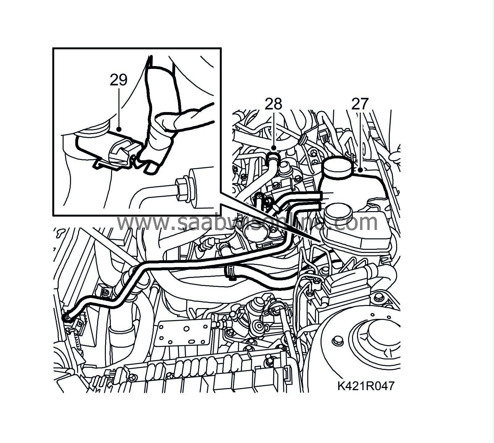
27.
|
Fit the expansion tank together with the hose.
|
|
28.
|
Attach the vent hose to the engine.
|
|
29.
|
Plug in the coolant level sensor connector.
|
|
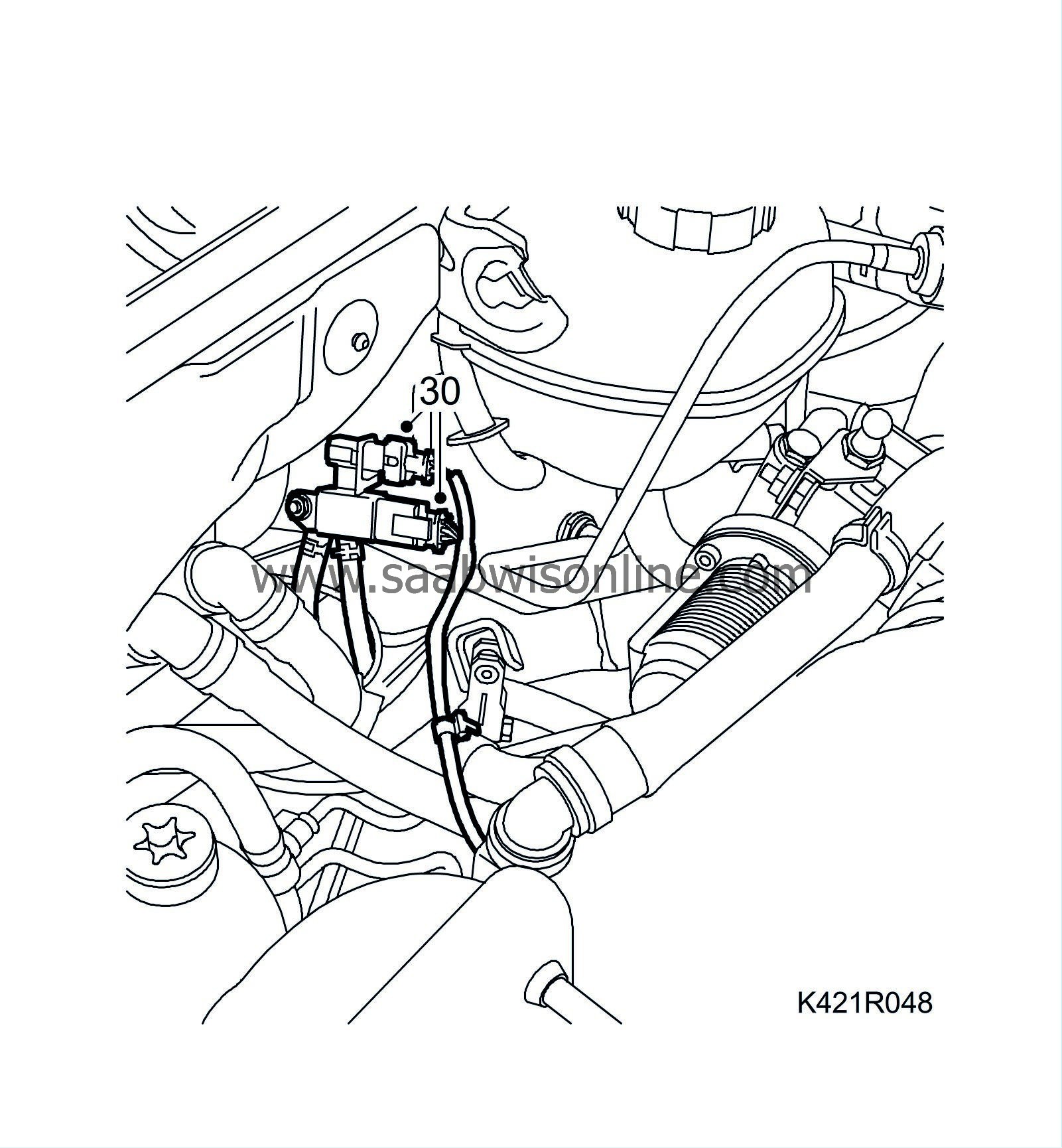
30.
|
Fit the rear temperature sensor and plug in the connector of the particle filter pressure sensor.
|
|
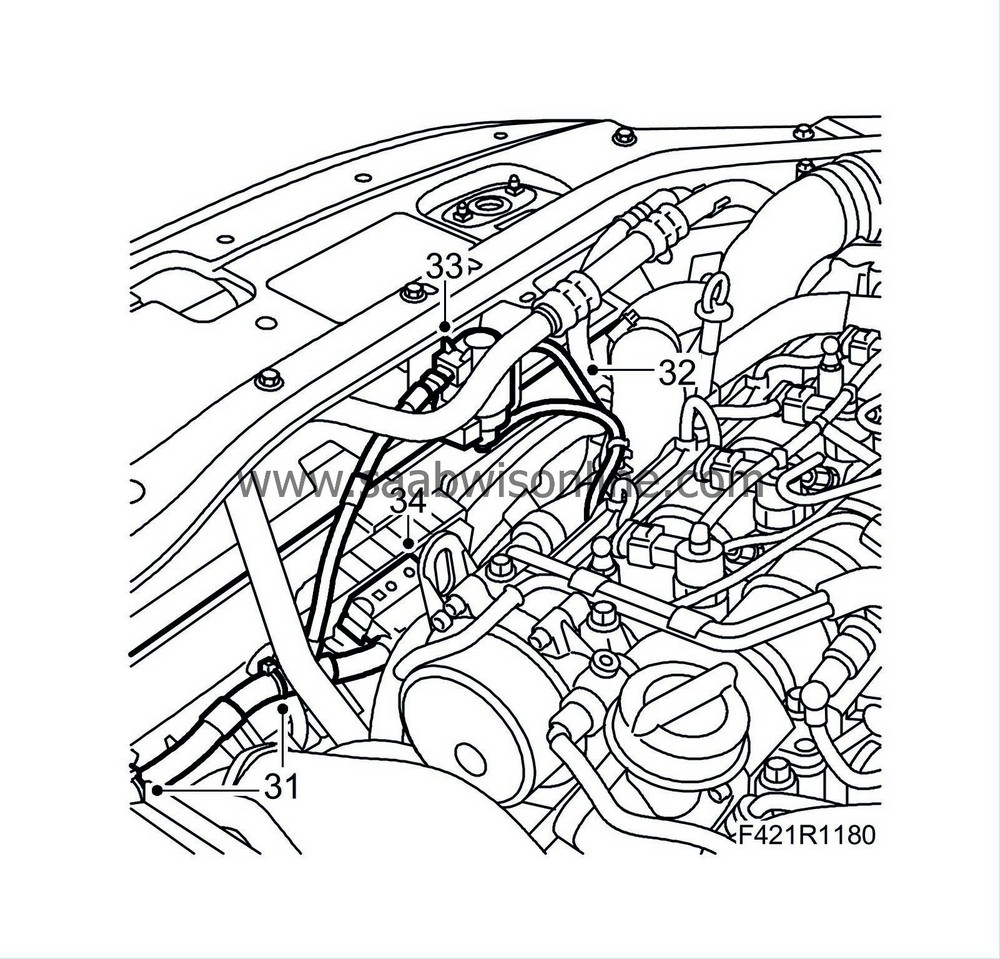
31.
|
Attach the wiring harness to the fan cowling.
|
|
32.
|
Attach the vacuum hoses to the turbo solenoid valve.
|
Note
|
|
"VAC" should be connected to the vacuum pump and "OUT" should be connected to the turbocharger.
|
|
|
33.
|
Plug in the connector to the turbo solenoid valve.
|
|
34.
|
Attach the radiator fan connector.
|
|
35.
|
Attach the connector to the left structural member.
|
|
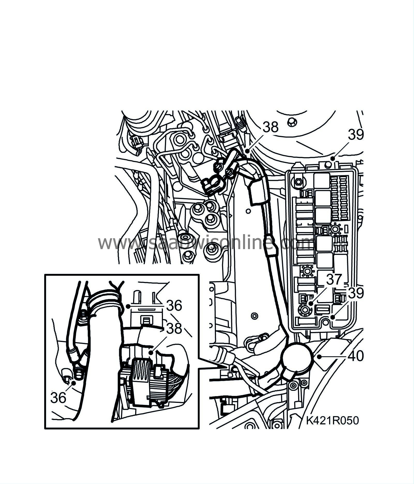
36.
|
Attach the ground cables and the clamp for the engine harness to the body.
|
|
37.
|
Tighten the screw securing the engine wiring harness connector in the electrical centre.
|
|
38.
|
Attach the positive cable to the positive terminal of the battery.
|
|
39.
|
Fit the two bolts securing the electrical centre and the cover.
|
|
40.
|
Fit the windscreen washer fluid filler pipe.
|
|
41.
|
Aut:
Attach the oil pipes to the radiator.
|
|
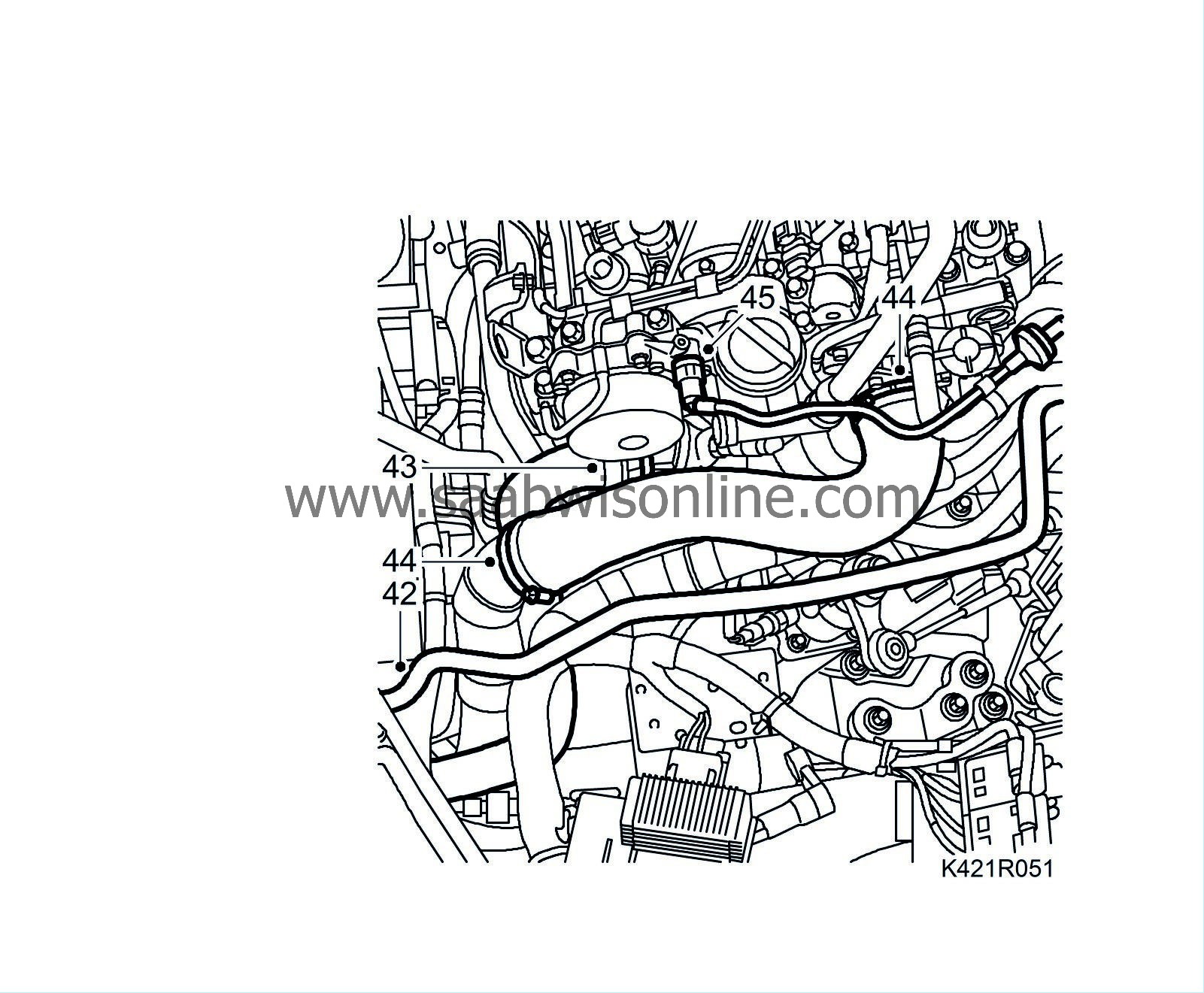
42.
|
Attach the bleeder hose to the radiator.
|
|
43.
|
Fit the upper radiator hose.
|
|
44.
|
Fit the turbocharger delivery hose to the throttle body and the turbo delivery pipe.
|
Important
|
|
To reduce the risk of hoses mounted on the delivery side of the turbocharger coming loose due to low friction at high air pressure, the hoses and connecting pieces must be cleaned thoroughly before fitting. Use a rag dampened with 93 160 907 Motip Dupli cleaning agent to wipe clean inside the ends of the hoses. Clean the connecting pieces as well. If hose clips are rusty or damaged, they must be replaced so the correct clamping force is maintained.
|
|
|
|
|
45.
|
Connect the hose with quick coupling to the vacuum pump.
|
|
46.
|
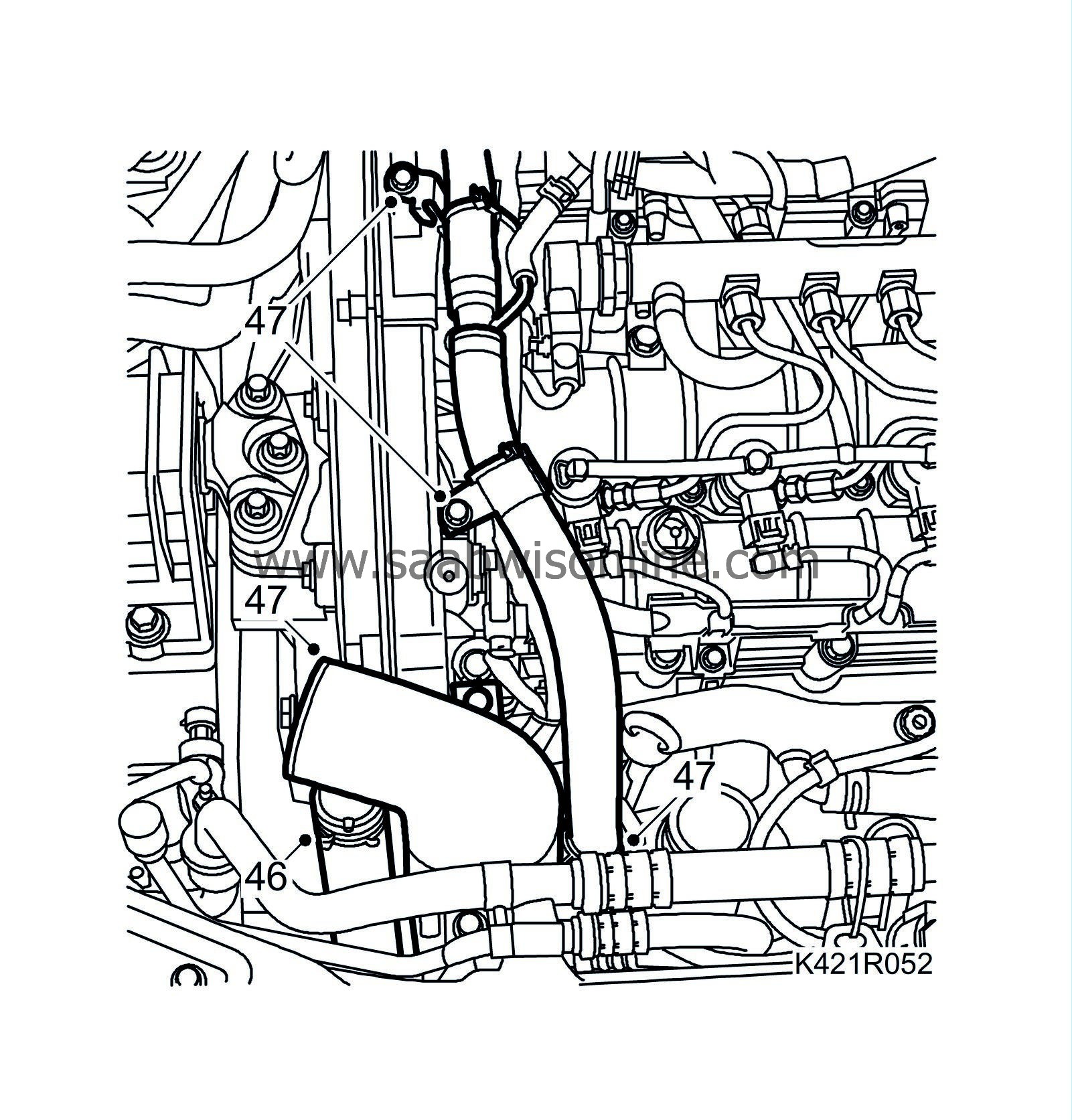
Attach the lower radiator hose to the engine.
|
|
47.
|
Attach the crankcase ventilation hose and fit the turbocharger intake manifold.
|
Note
|
|
Take extra care in cars with preheated crankcase ventilation to ensure that the heating coil in the hose is not damaged.
|
|
|
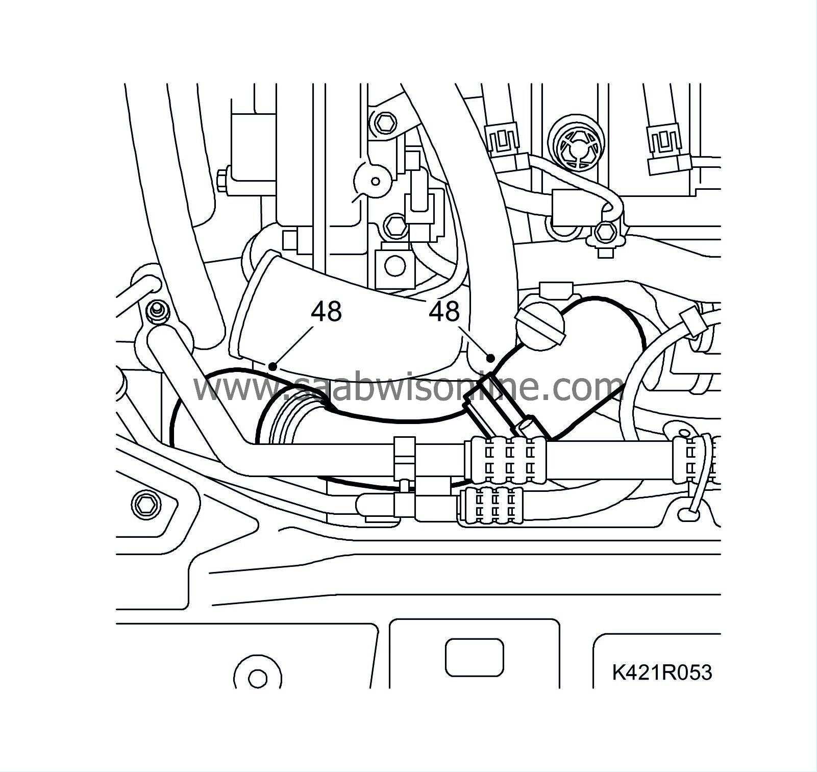
48.
|
Fit the hose to the turbocharger outlet and the turbocharger delivery pipe.
|
|
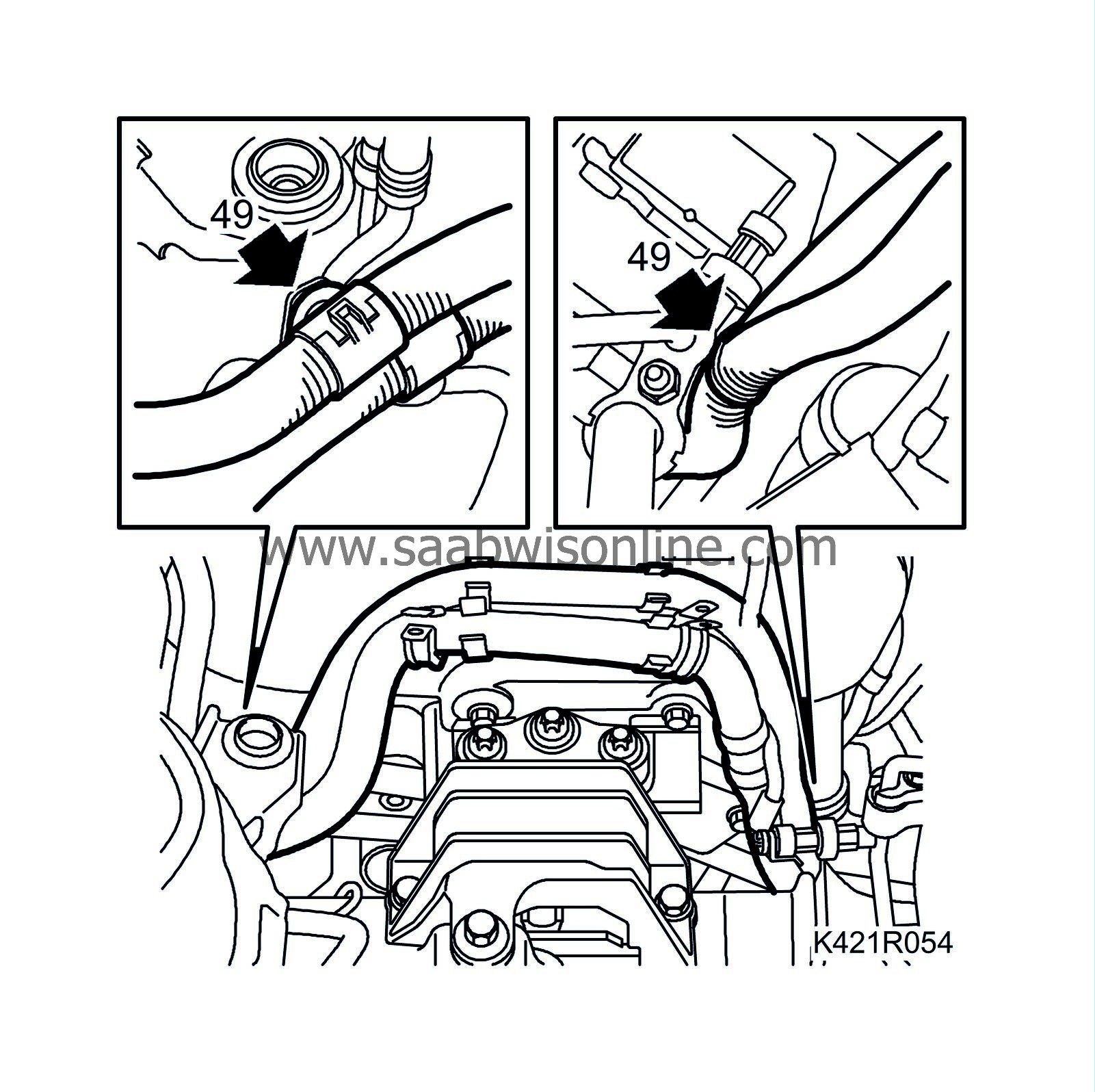
49.
|
Position the engine control module's wiring harness and install the fixings to the right structural member (front and rear).
|
|
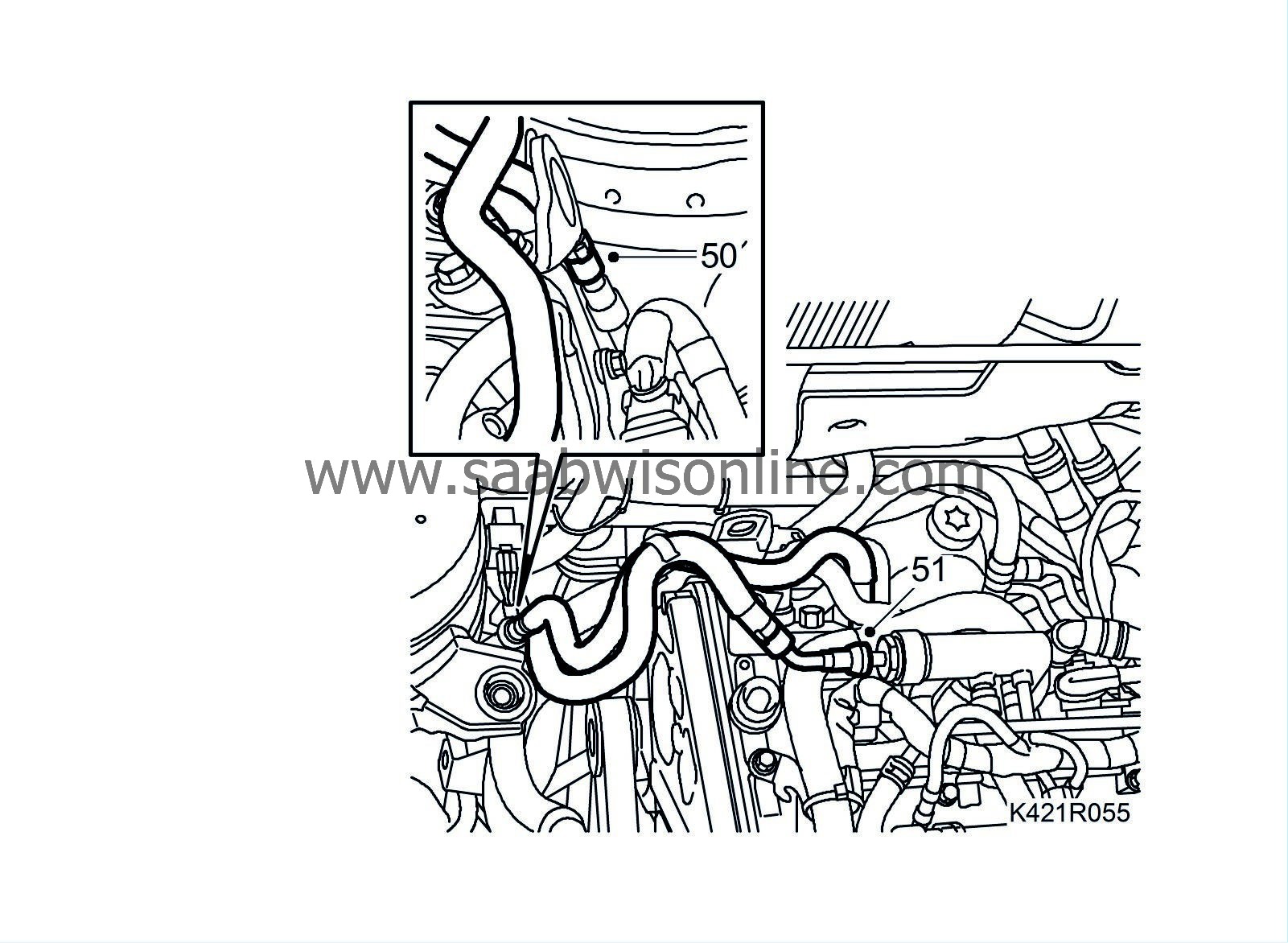
50.
|
Attach the fuel intake hose.
|
Warning
|
|
The work involved in removing the fuel pipe requires working with the vehicle's fuel system. The following points should therefore be heeded in conjunction with these measures:
|
|
• Have a class BE fire extinguisher on hand! Be aware of the risk of sparks, i.e. in connection with electric circuits, short-circuiting, etc.
|
|
• Absolutely No Smoking!
|
|
• Ensure good ventilation! If there is approved ventilation for evacuating fuel fumes then this must be used.
|
|
• Wear protective gloves! Prolonged exposure of the hands to fuel can cause irritation to the skin.
|
|
• Wear protective goggles.
|
|
|
|
|
|
|
|
51.
|
Attach the fuel return hose.
|
|
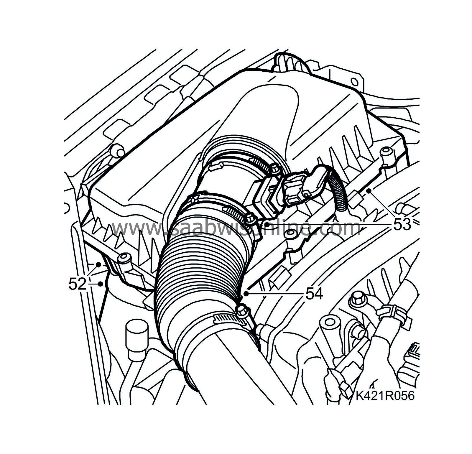
52.
|
Fit the air cleaner casing and connect the inlet hose.
|
|
53.
|
Fit the air filter, air cleaner casing cover and the mass air flow sensor connector.
|
|
54.
|
Fit the turbocharger inlet hose.
|
|
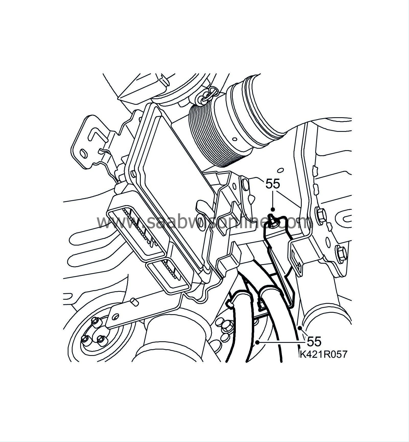
55.
|
Attach the engine harness and fit the bracket to the body.
|
|
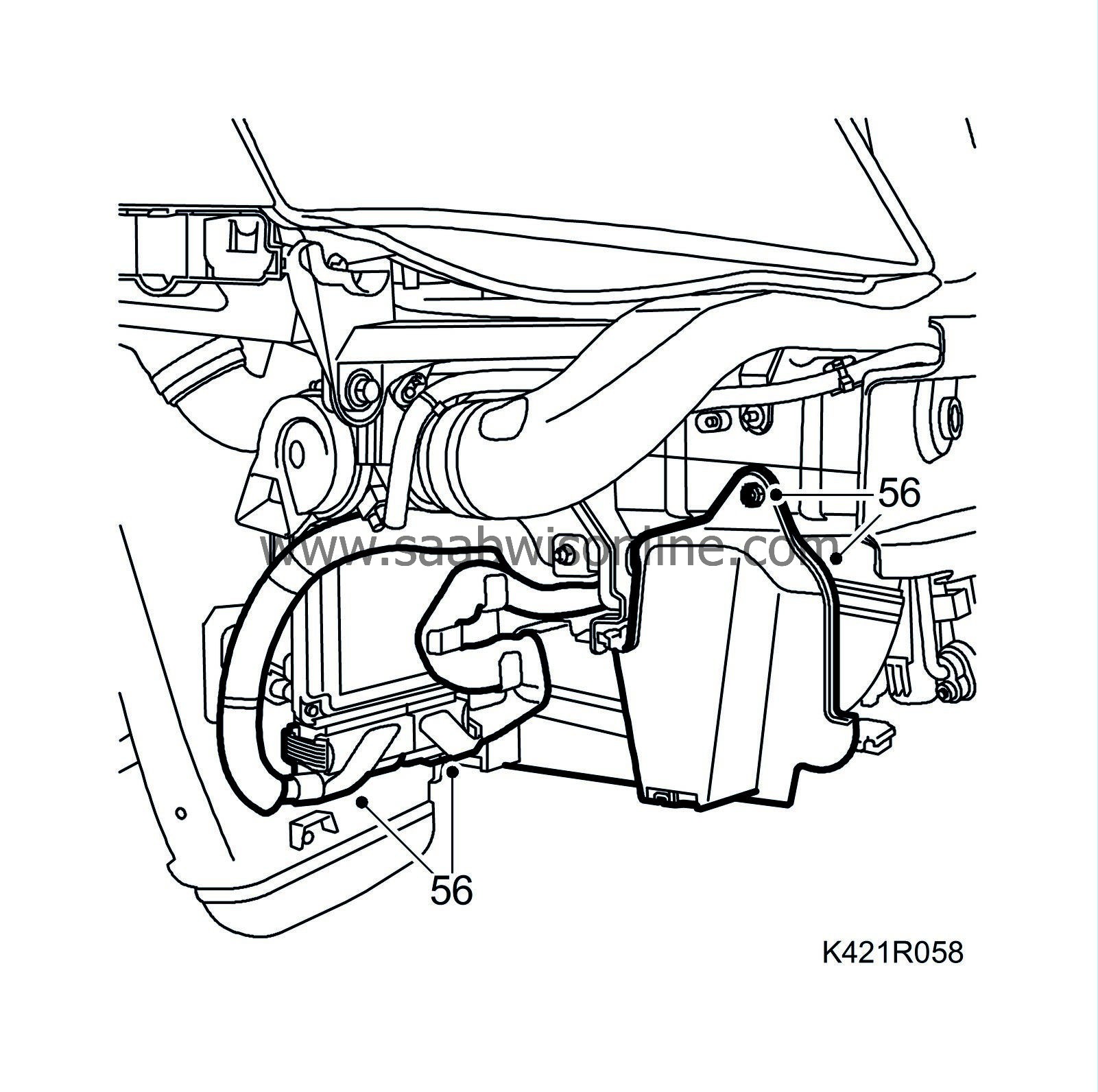
56.
|
Fit the clips and attach the connectors to the engine control module. Fit the cover on the right side.
|
|
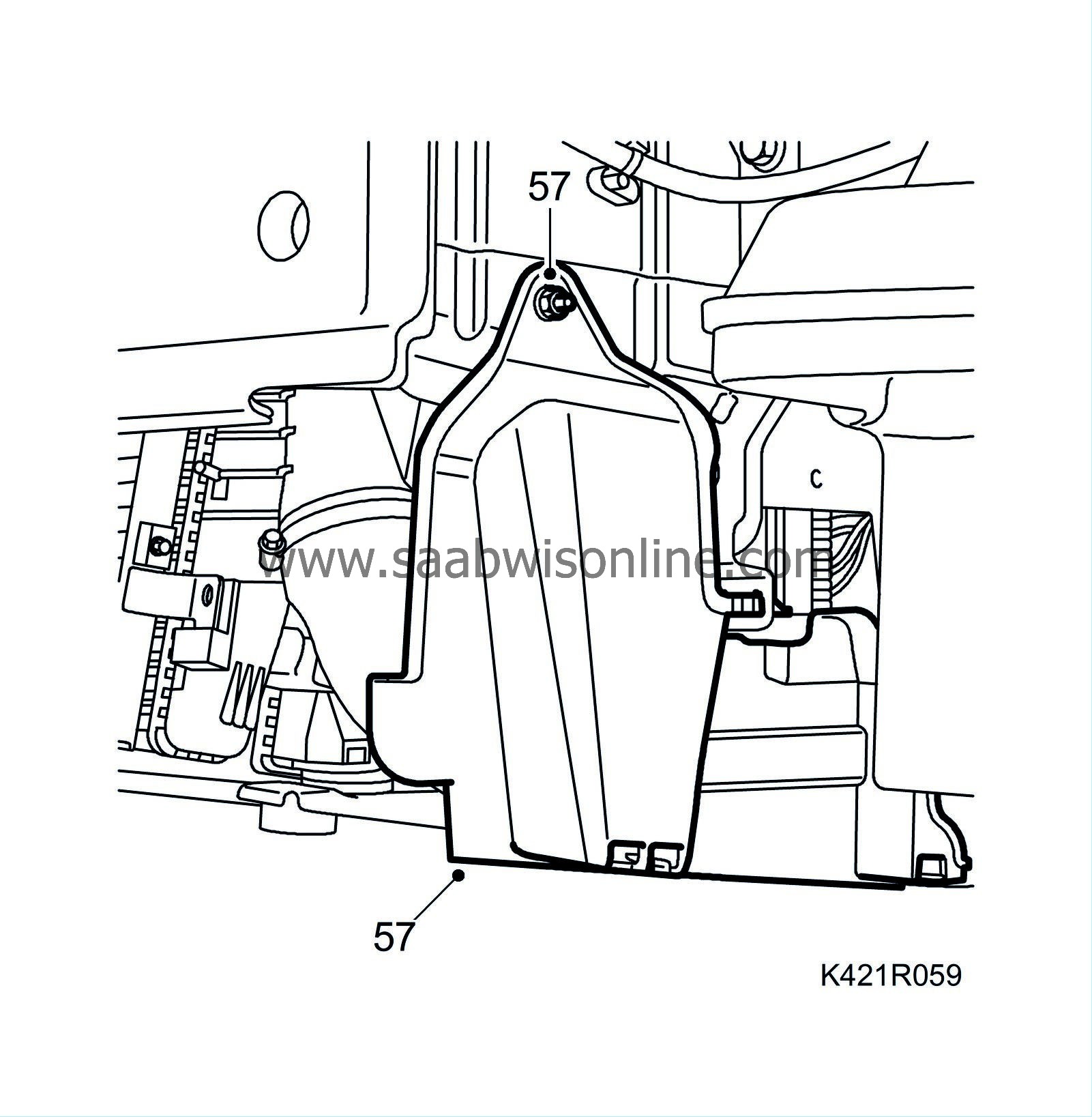
57.
|
Fit the cover on the left-hand side.
|
|
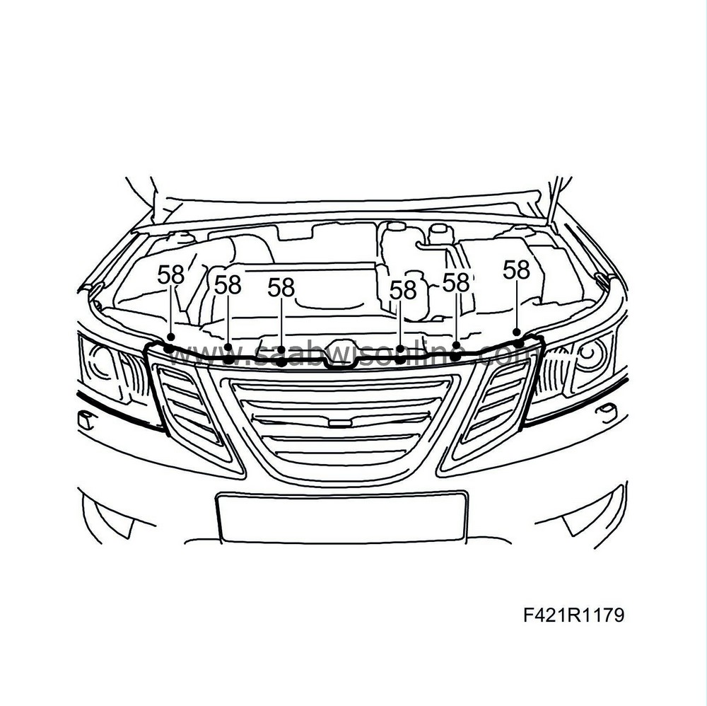
58.
|
Raise the car slightly and fit the bumper.
|
|
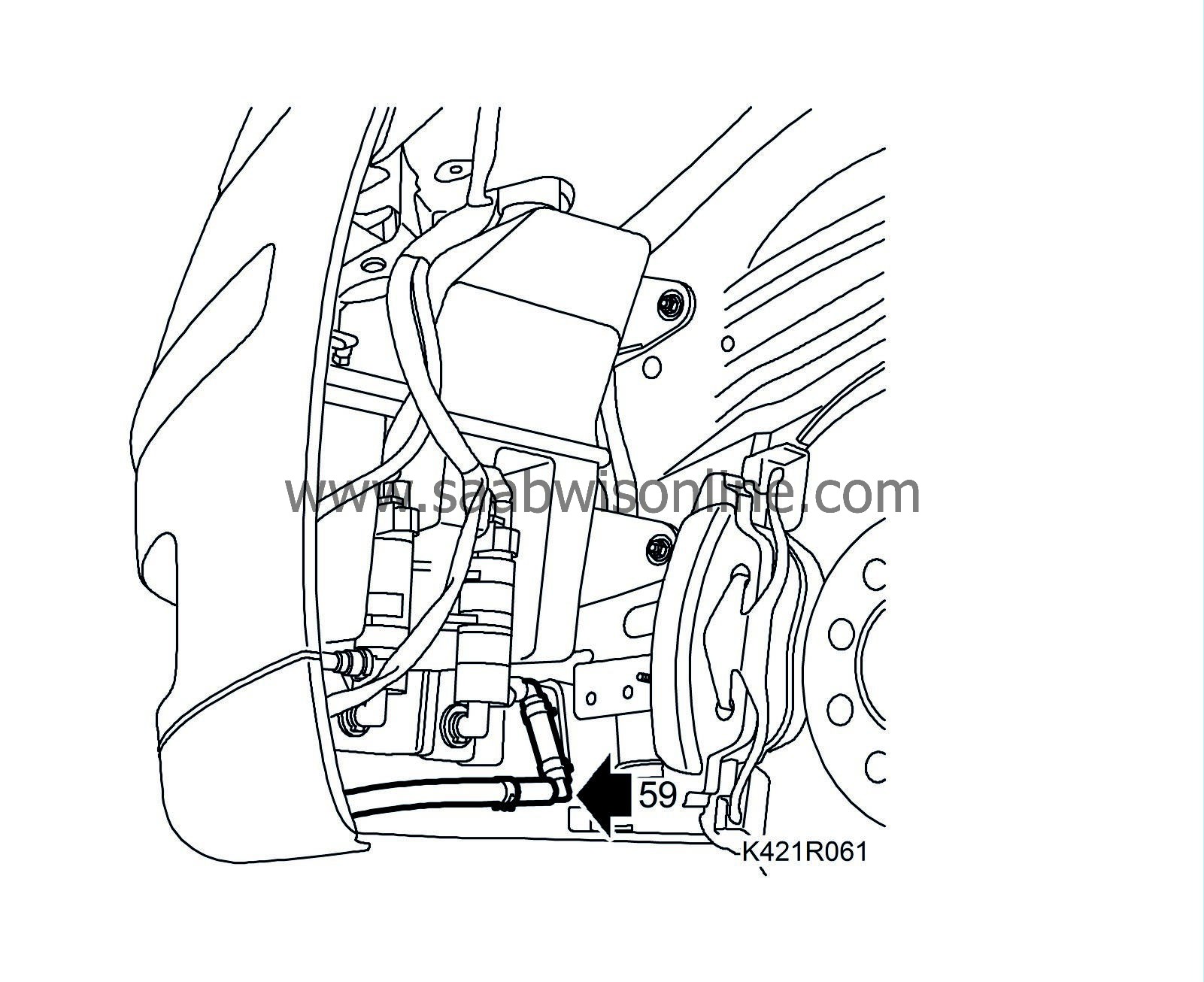
59.
|
Remove the plug and attach the headlight washer hose.
|
|
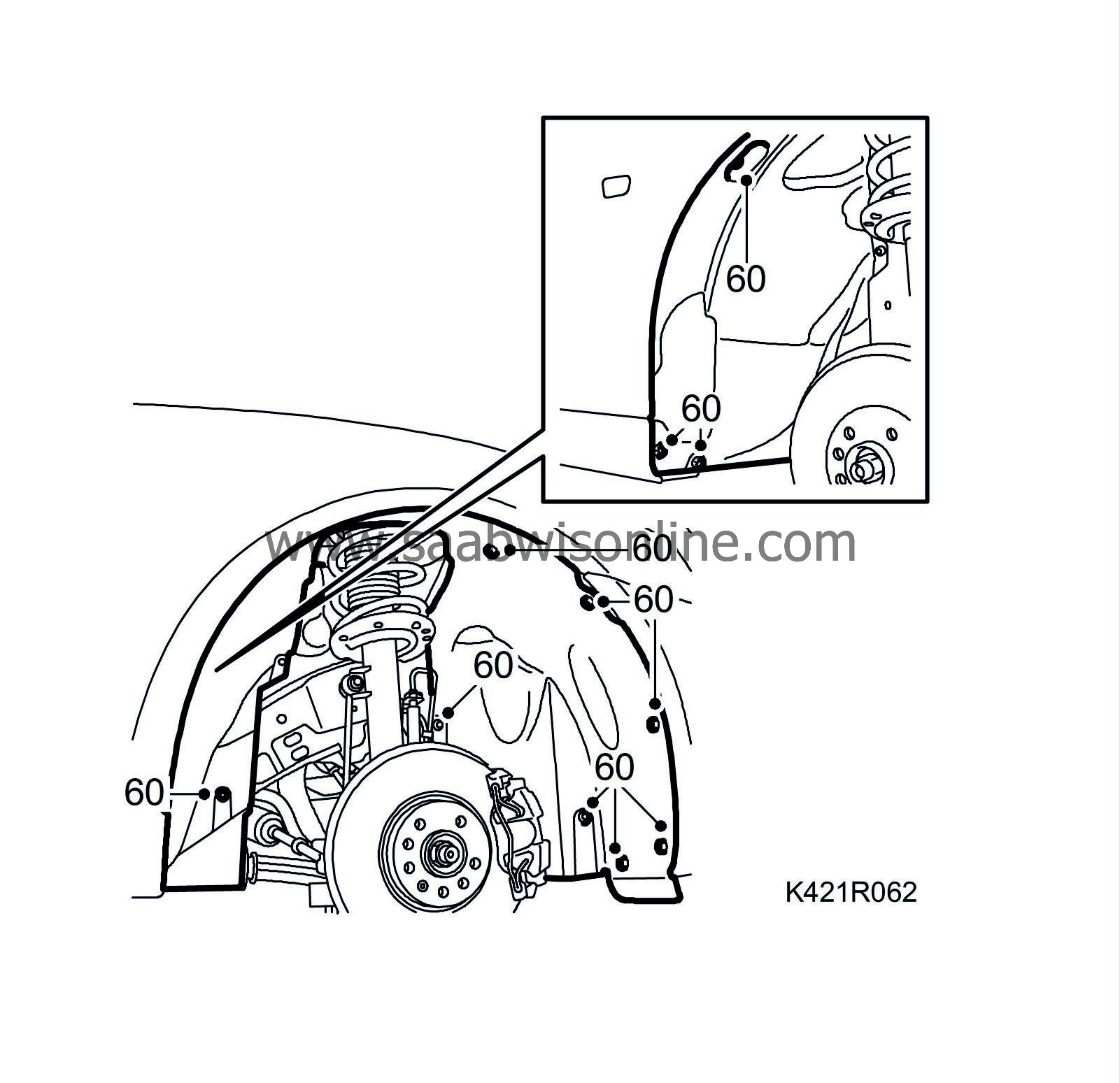
60.
|
Fit the front section of the left wing liner and the right wing liner.
|
|
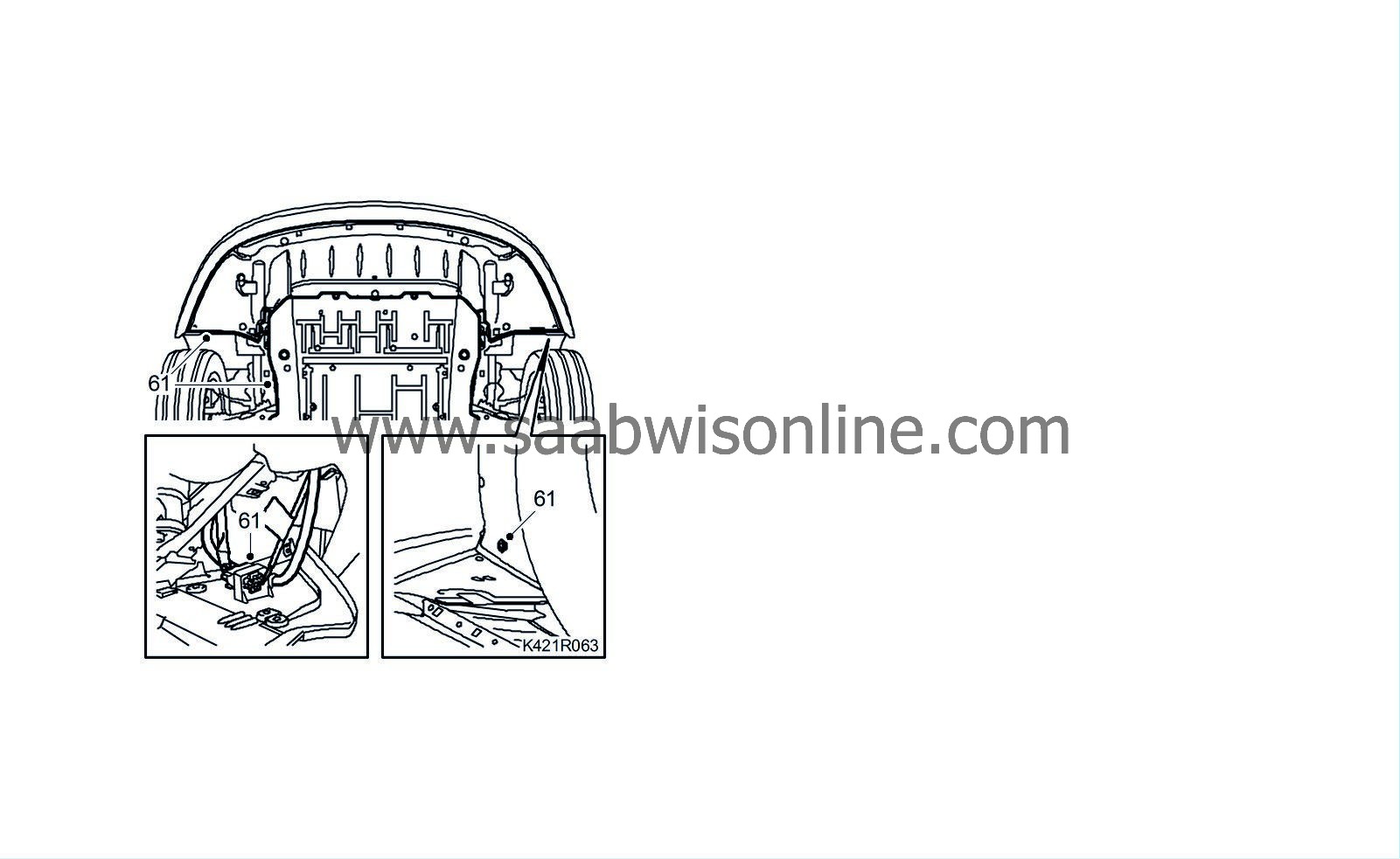
61.
|
Raise the car and plug in the connector. Fit the front spoiler shield and the lower engine cover.
|
|
62.
|
Lower the car slightly and mount the front wheels. See
Wheels
.
|
|
63.
|
Lower the car and tighten the hub nuts of the drive shafts.
Tightening torque 230 Nm (170 lbf ft).
|
|
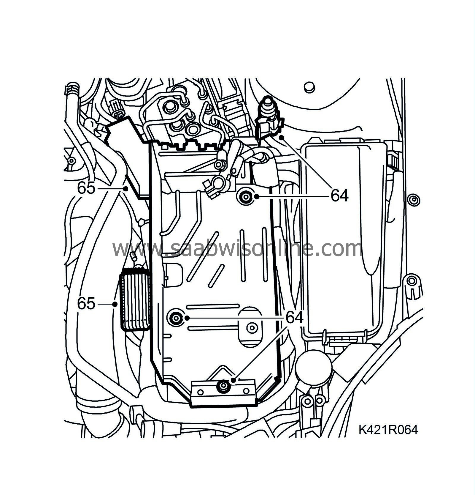
64.
|
Fit the battery tray and plug in the bonnet switch connector.
|
|
65.
|
Fit the fuse holder to the battery tray and the glow plug control module.
|
|
67.
|
Fit the battery cable.
|
|
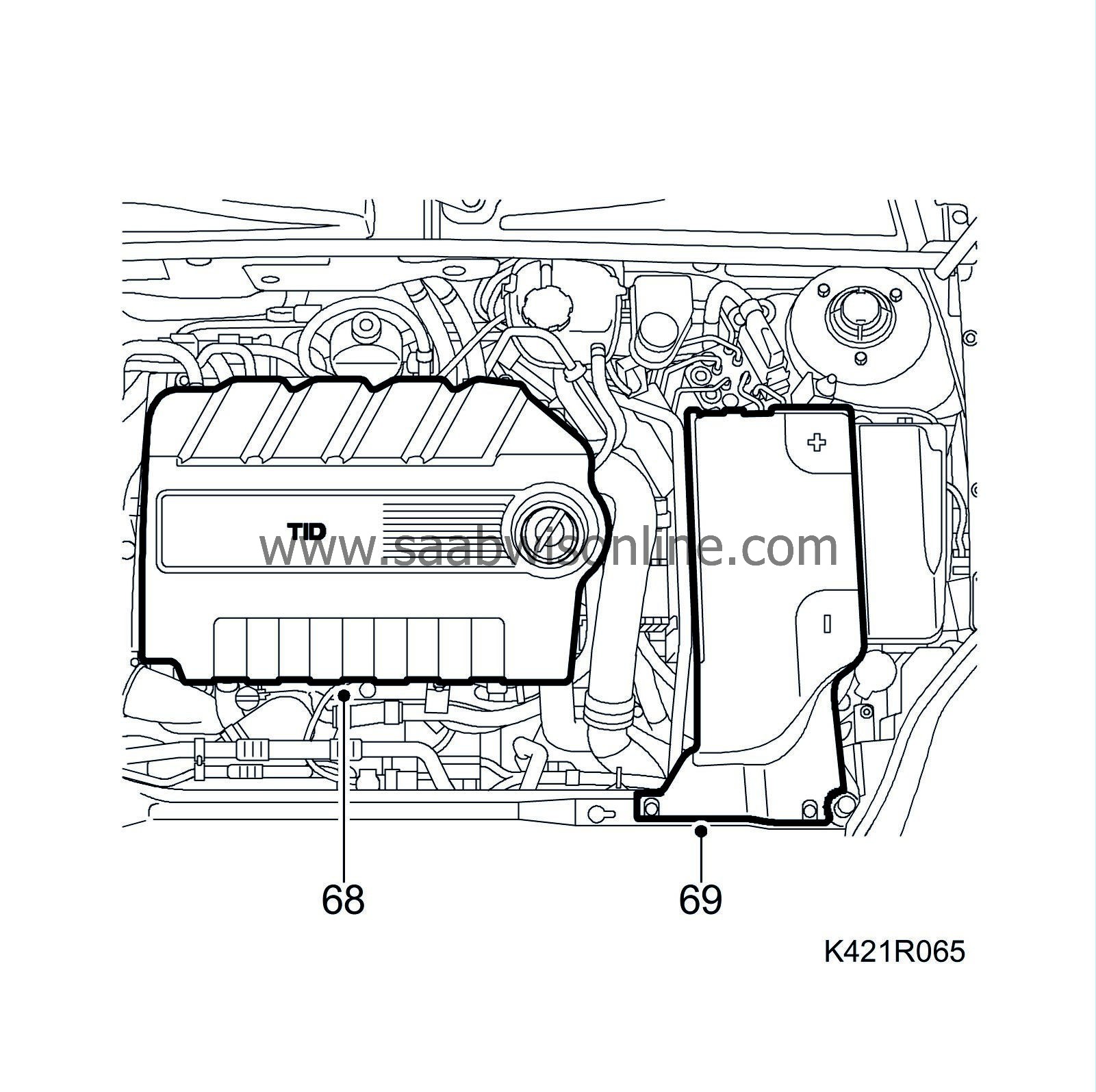
68.
|
Fit the insulation, upper engine cover and battery cover.
|
|
69.
|
Fit the battery cable.
|
|
70.
|
Check oil level and top up as necessary. Fill with coolant to approx. 20 mm above the mark on the expansion tank. If a new engine is fitted, follow the instructions given in Bleeding the cooling system when working on the oil cooler.
|
|
71.
|
Aut:
If the gearbox was drained, check the automatic transmission fluid level as described in
Fluid level check
.
Man:
Fill the fluid in the gearbox.
|


