Powertrain, removal, Z19DTR
|
|
Powertrain, removal, Z19DTR
|
|
1.
|
Position the car on a lift. Set the selector lever to position P and remove the key. The wheels should be in the straight-ahead position. Protect the wings against paintwork damage and soiling.
 Warning
|
|
The cooling system is under pressure. Hot coolant and steam can escape.
|
|
- Open the cap slowly to release the pressure.
|
|
- Carelessness can cause eye and burn injuries
|
|
|
|
|
|
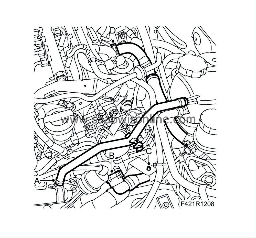
|
|
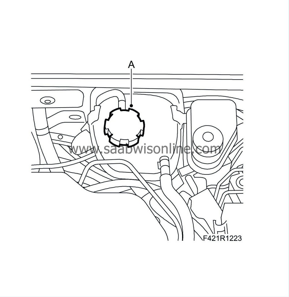
2.
|
Open the expansion tank cap (A).
|
|
3.
|
Remove the upper engine cover and insulation.
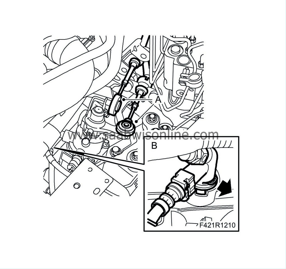
|
|
6.
|
Raise the car slightly and remove the front wheels.
|
|
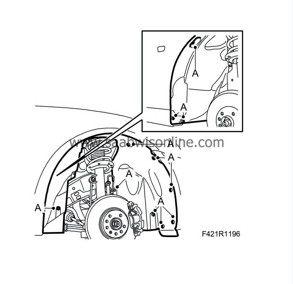
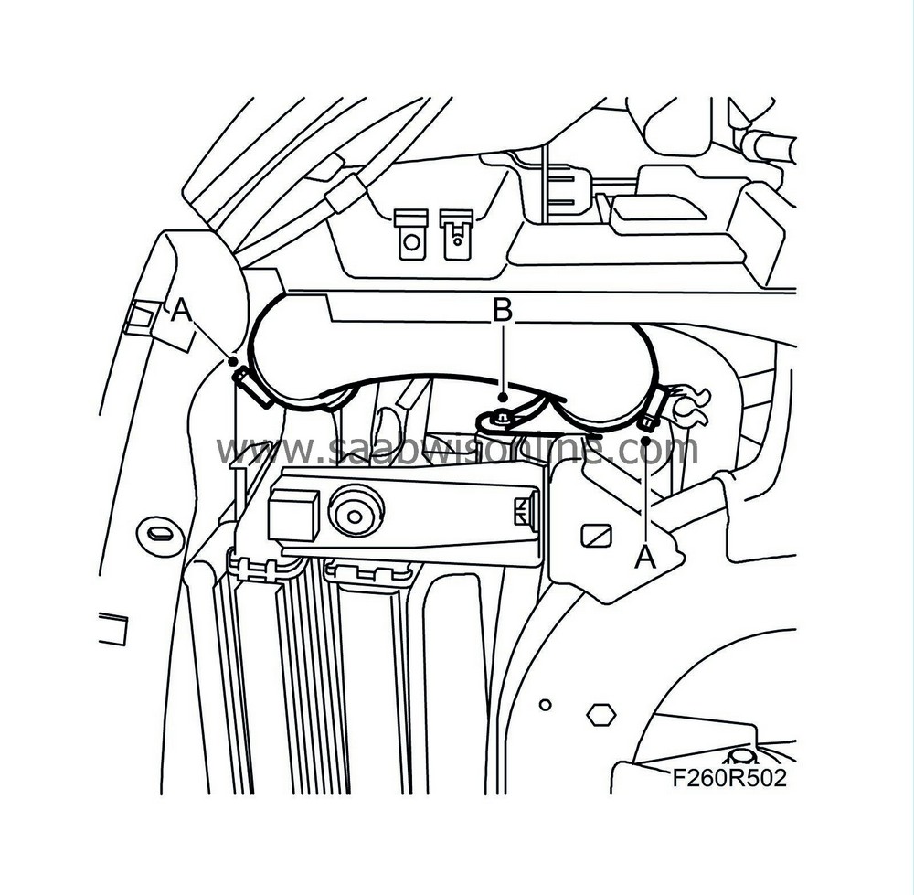
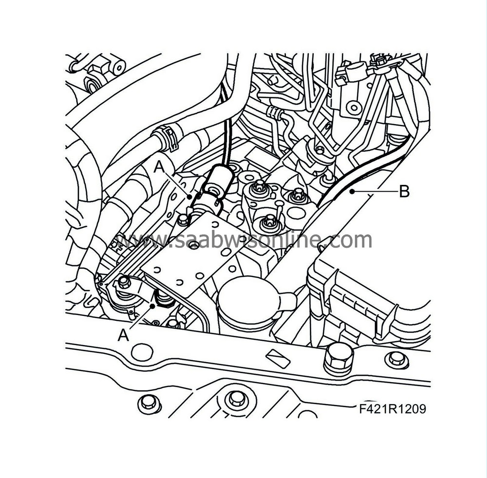
7.
|
Remove the right wing liner (A) and detach the front part of the left wing liner so that the subframe is free.
|
|
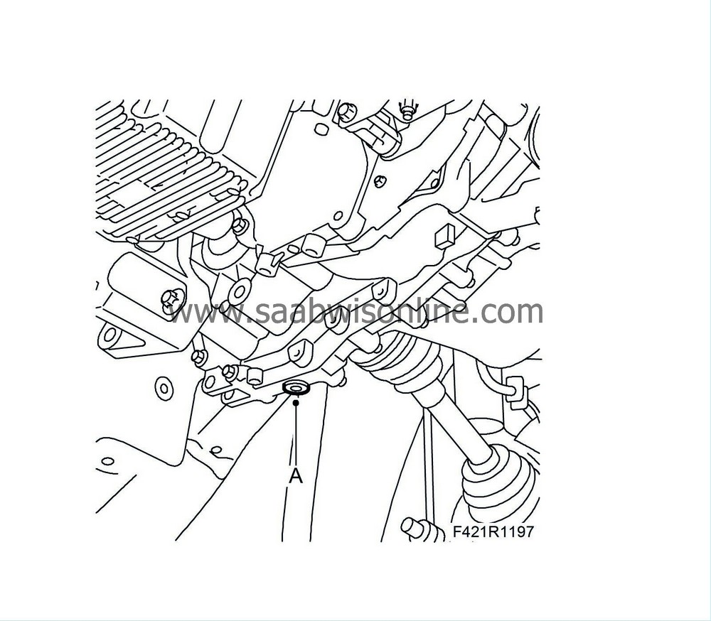
8.
|
Man
: Slacken the gearbox drain plug (A) and drain the gearbox oil.
|
|
9.
|
Man
: Fit the drain plug (A).
Tightening torque 50 Nm (37 lbf ft)
|
|
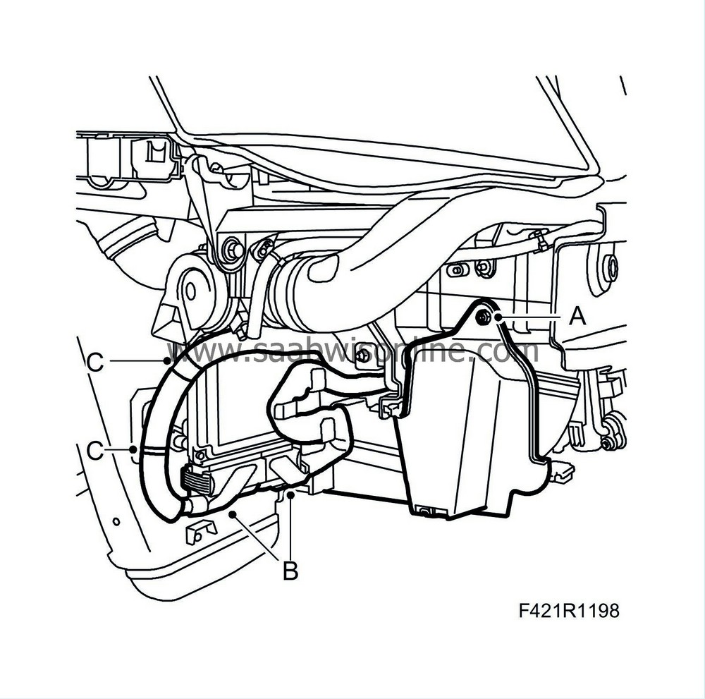
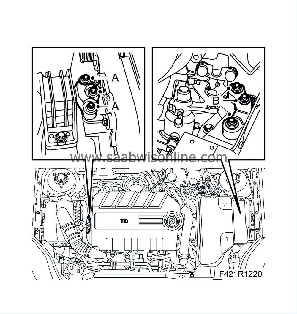
10.
|
Place a suitable receptacle under the radiator. Connect a hose (A) to the radiator (B) and drain the coolant.

|
|
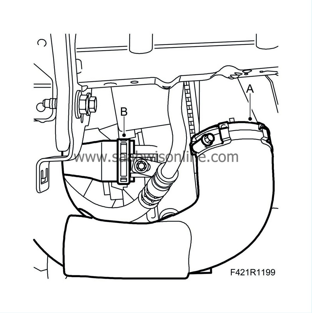
11.
|
Remove the cover (A) on the right side, unplug the connectors (B) from the engine control module and remove the clips (C).
|
|
12.
|
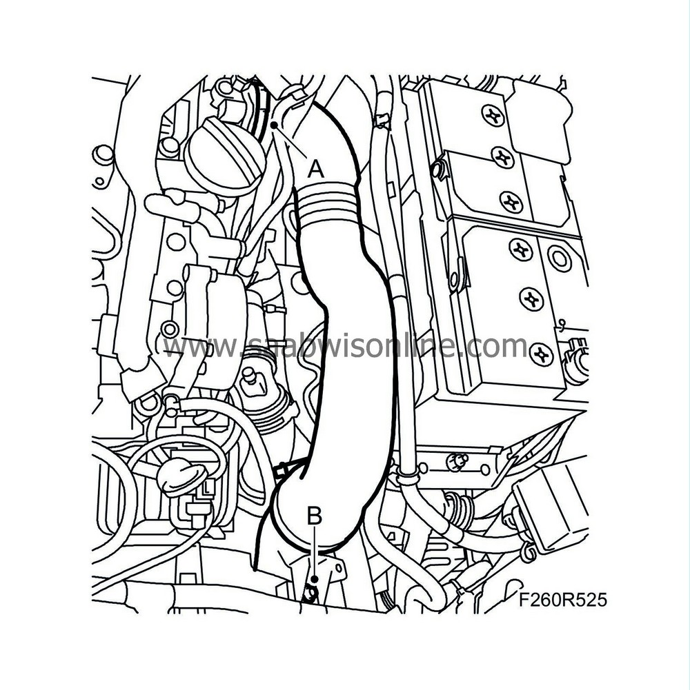
Remove the hose clip of the air hose (A).
|
|
13.
|
Detach the lower radiator hose (B) from the radiator.
|
|
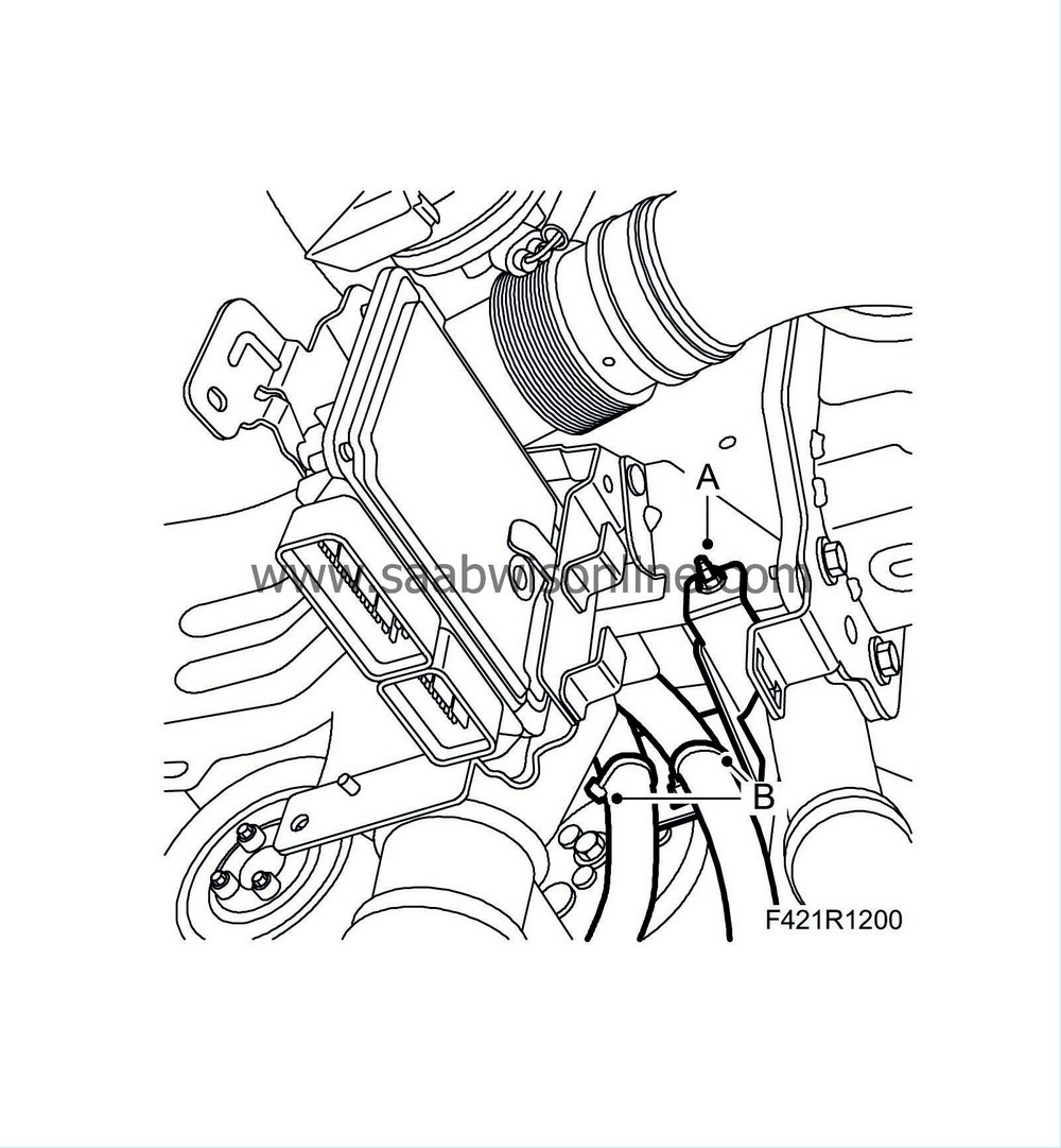
14.
|
Remove the bracket (A) from the body and remove the cable ties (B) of the wiring harness.
|
|
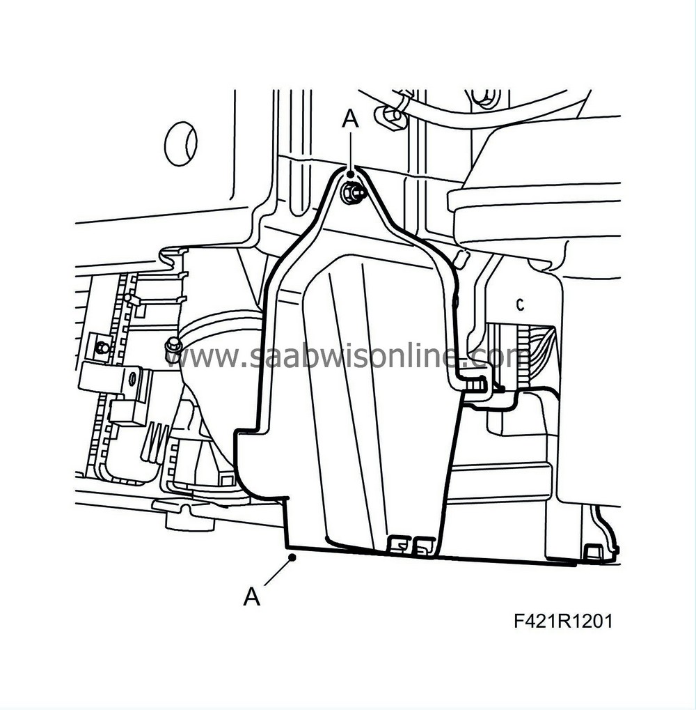
15.
|
Remove the cover (A) on the left side.
|
|
16.
|
Remove the turbo delivery pipe's hose clip (A) and the pipe's screw (B) from the radiator.
|
|
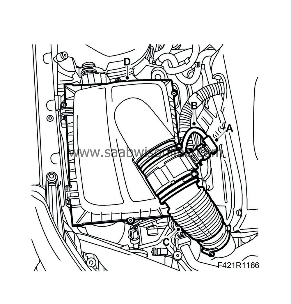
18.
|
Detach the mass air flow sensor's connector (A), wiring harness (B), hose (C) and the air filter housing's cover (D) and filter. Plug the intake manifold with a clean cloth.
|
|
19.
|
Remove the air filter housing.
|
Warning
|
|
The work involved in removing the fuel pipe requires working with the vehicle's fuel system. The following points should therefore be heeded in conjunction with these measures:
|
|
• Have a class BE fire extinguisher on hand! Be aware of the risk of sparks, i.e. in connection with electric circuits, short-circuiting, etc.
|
|
• Absolutely No Smoking!
|
|
• Ensure good ventilation! If there is approved ventilation for evacuating fuel fumes then this must be used.
|
|
• Wear protective gloves! Prolonged exposure of the hands to fuel can cause irritation to the skin.
|
|
• Wear protective goggles.
|
|
|
|
|
|
|
Important
|
|
Be very thorough in terms of cleanliness when working in the fuel system. Malfunctions can also occur due to very small dirt particles. Prevent dirt from entering the fuel system by cleaning the hoses and plugging the pipes and lines upon removal. Store the components so that contaminants cannot enter.
|
|
|
|
|
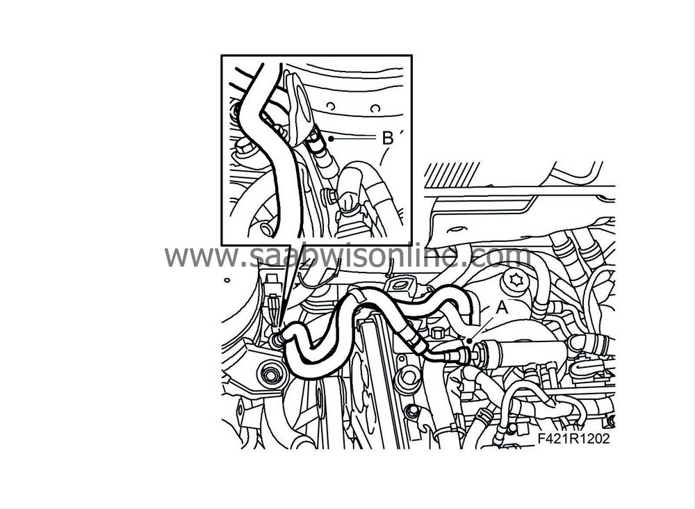
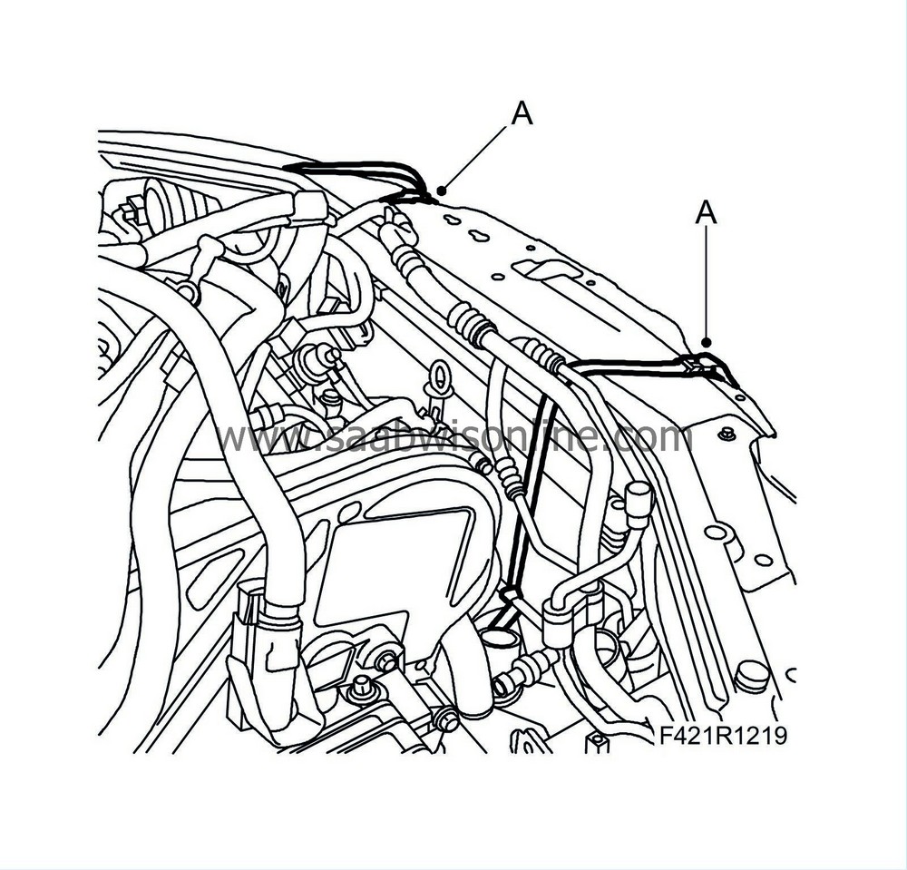
20.
|
Detach the fuel return hose (A). Plug both the hose and the pipe.
|
|
21.
|
Detach the intake fuel hose (B). Plug both the hose and the pipe.
|
|
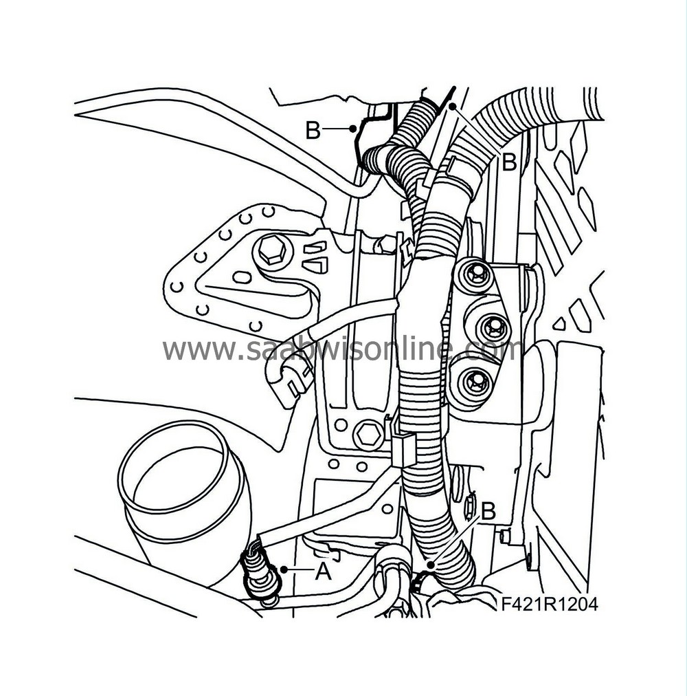
22.
|
Remove the bracket of the engine wiring harness (A).
|
|
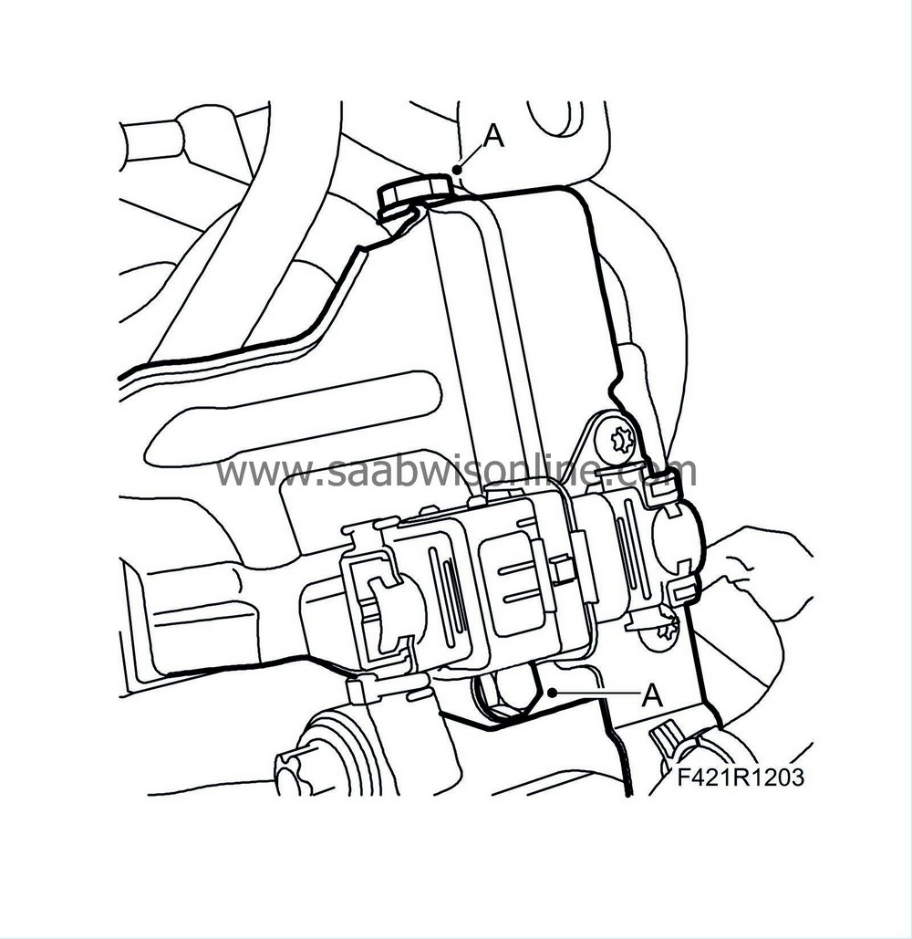
23.
|
Unplug the A/C pressure sensor connector (A).
|
|
24.
|
Remove the fixings (B) from the right structural member and carefully raise the engine control module's wiring harness.
|
|
25.
|
Remove the turbo delivery hose's hose clip (A) at the throttle body and the turbo delivery pipe's screw (B) from the fan cowling. Remove the pipe and hose assembly.
|
|
26.
|
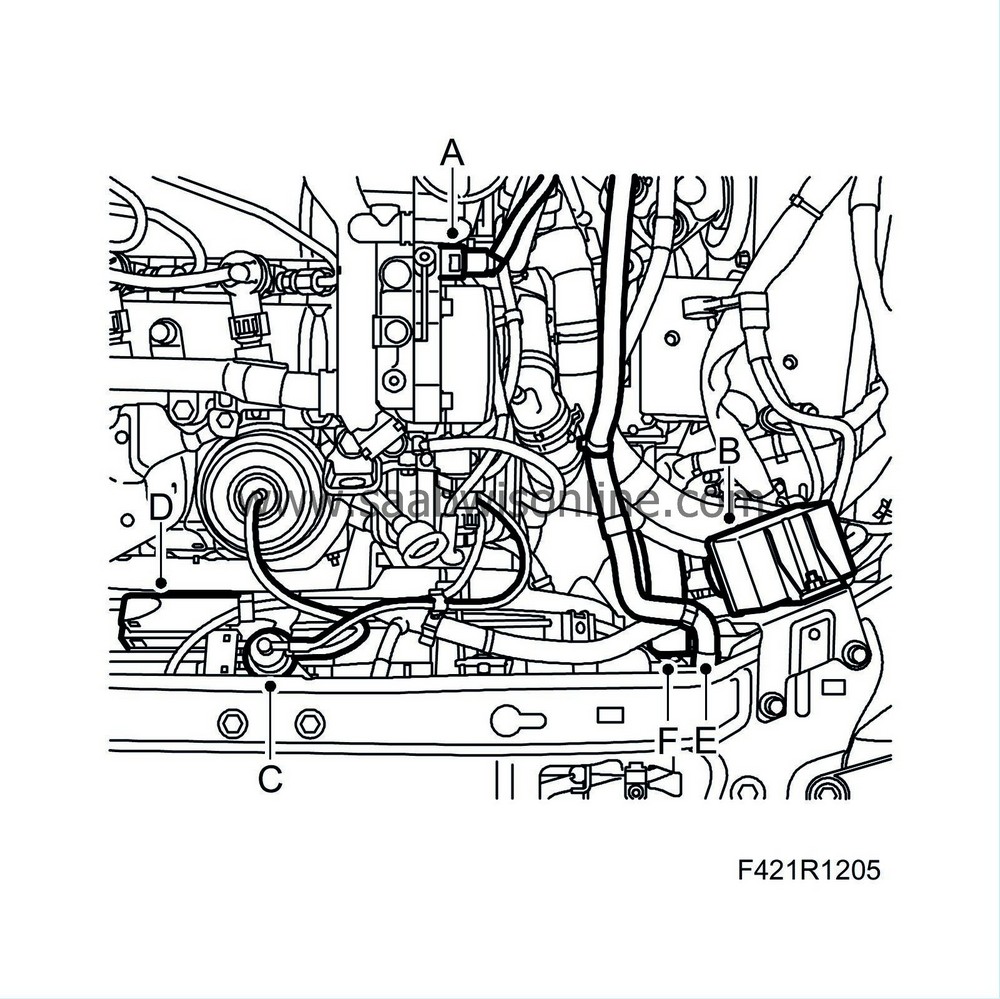
Remove the following:
|
|
|
-
|
Remove the hose with quick coupling (A) from the vacuum pump.
|
|
|
-
|
Remove the glow plug control module (B).
|
|
|
-
|
Remove the boost pressure valves (C).
|
|
|
-
|
Detach the radiator fan connector (D) and clips.
|
|
|
-
|
Detach the bleeder hose (E), undo the clips and put aside.
|
|
|
-
|
Detach the upper radiator hose (F).
|
|
28.
|
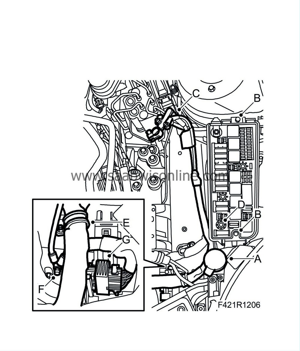
Remove the following:
|
|
|
-
|
Remove the windscreen washer filler pipe (A).
|
|
|
-
|
Remove the cover of the electrical centre.
|
|
|
-
|
Remove the two retaining bolts (B).
|
|
|
-
|
Disconnect the positive cable (C) from the positive terminal of the battery.
|
|
|
-
|
Slacken the retaining bolt (D) of the engine harness connector in the electrical centre and remove the connector.
|
|
|
-
|
Detach the engine harness clamp (E) from the body.
|
|
|
-
|
Disconnect the ground cables (F).
|
|
|
-
|
Detach the connector (G) from the left structural member.
|
|
29.
|
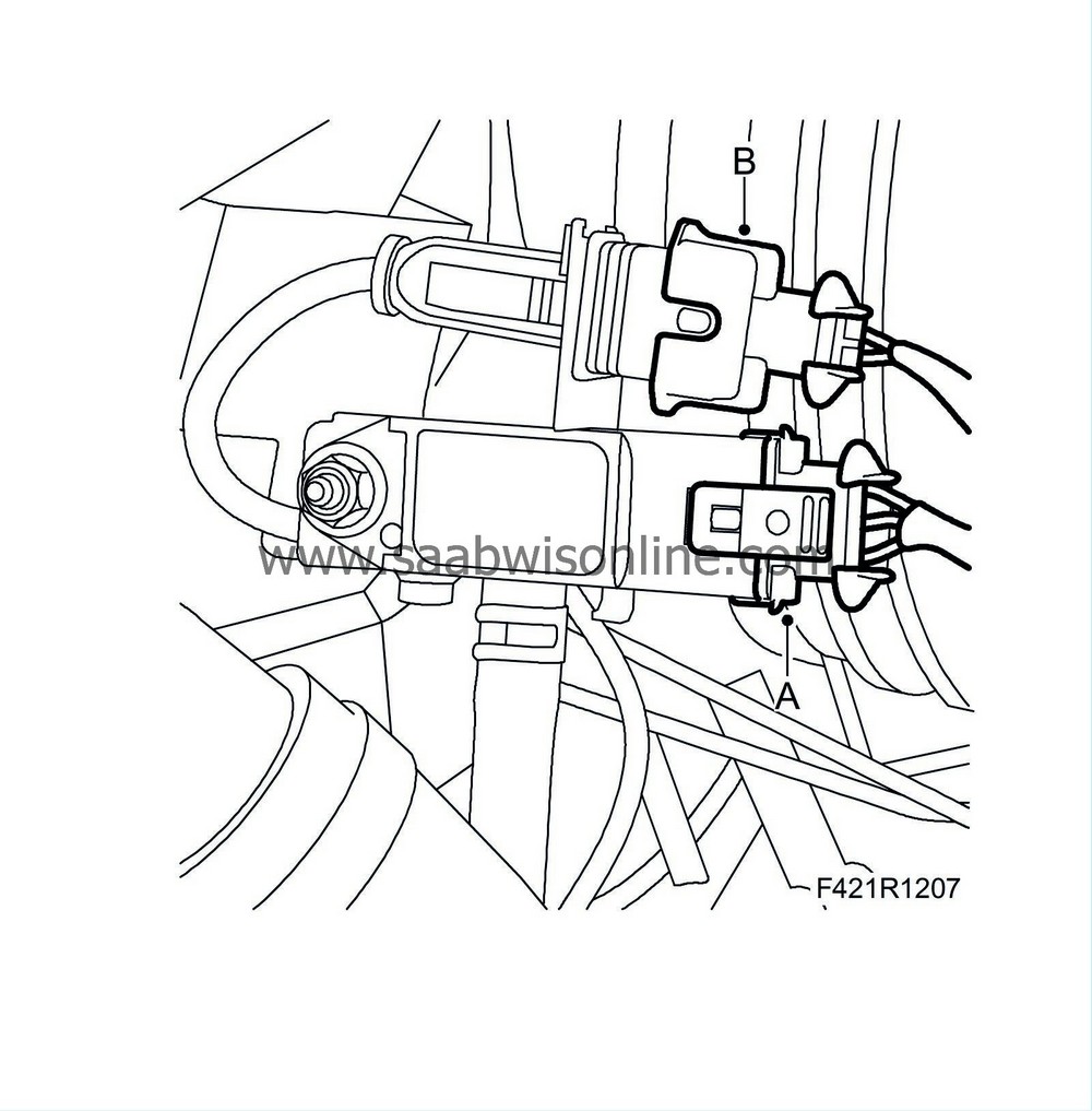
Detach the connector (A) from the particle filter pressure sensor and the connector (B) from the rear temperature sensor.
|
|
30.
|
Fold up the engine wiring harness onto the engine.
|
|
31.
|
Detach the bleeder hose (A) from the engine.
|
|
32.
|
Remove the quick coupling of the EGR cooler's water port (B) and undo the clips (C).
|
|
33.
|
Detach the hose (D) of the rear radiator core.
|
|
34.
|
Aut:
Remove the gear cable (A) and secure it to the expansion tank mounting using a cable tie.
|
|
35.
|
Aut:
Detach the hose (B) for automatic transmission bleeding.
|
|
36.
|
Man:
Detach the gear cables (A) from the gearbox. Carefully move them aside and secure them to the expansion tank mounting in the body using a cable tie.
|
|
37.
|
Man:
Fit
30 07 739 Hose pinch-off pliers
on the clutch hose and remove the quick coupling (B) from the clutch slave cylinder.
|
Warning
|
|
In order to avoid the contact roller for the airbag twisting and breaking the steering wheel must be secured via the steering column lock or by taping it to the panel.
|
|
|
|
|
|
|
|
38.
|
Check and adjust the steering wheel and the steering assembly so that they are pointing straight ahead.
|
|
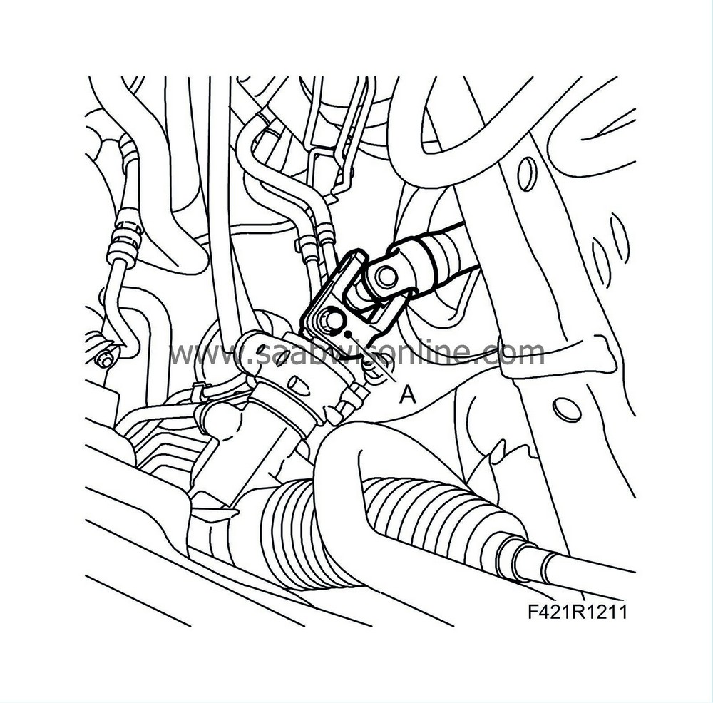
40.
|
Detach the steering shaft (A) from the steering gear.
|
|
41.
|
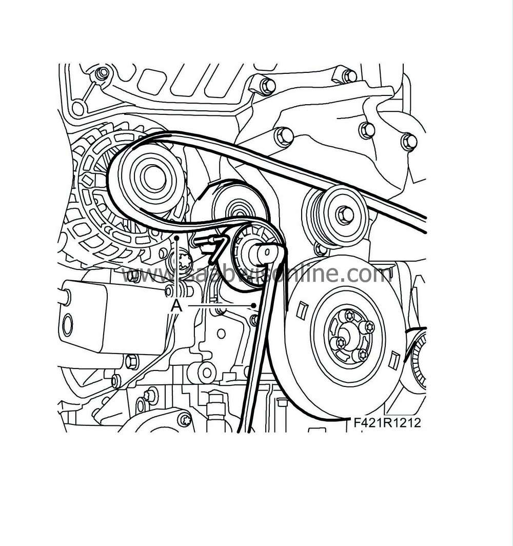
Remove the multigroove belt (A). Mark the direction of belt rotation.
|
|
42.
|
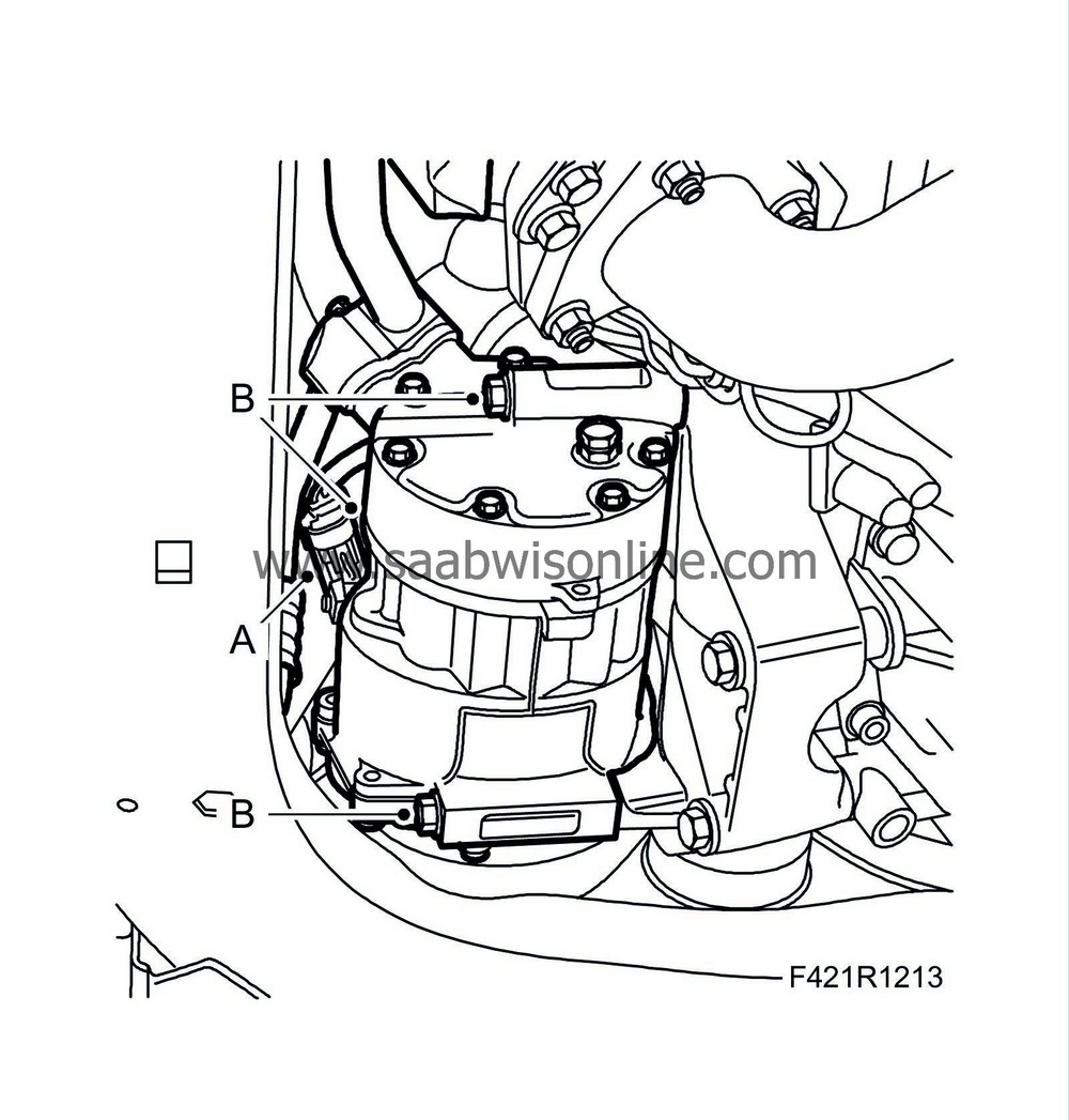
Unplug the A/C compressor connector (A) and remove the A/C compressor retaining bolts (B).
|
|
43.
|
Undo the drive shaft centre nuts. Knock loose the drive shafts from the hubs. Use 89 96 951 Puller, drive shaft or a brass drift with mallet.
|
|
44.
|
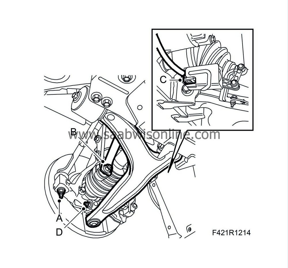
Undo the nuts (A) and the outer steering swivel members using 87 91 287 Puller, 150 mm.
|
|
45.
|
Undo the lower anti-roll bar links (B) while gripping the flats with a thin spanner.
|
|
46.
|
Certain cars:
Unplug the connector (C) of the headlamp angle sensor and detach the cable from the subframe.
|
|
47.
|
Undo the lower swivel joints (D) from the steering swivel members and pivot down the suspension arms.
|
|
48.
|
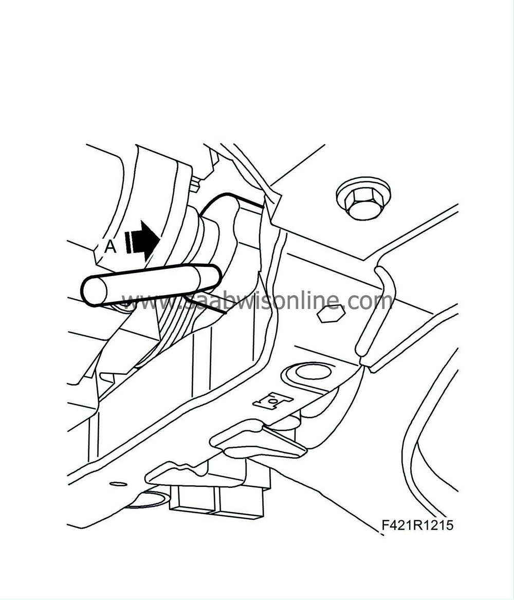
Remove the right drive shaft from the intermediate shaft (A).
|
|
49.
|
Remove the bracket (A) and the intermediate shaft (B).
Aut:
Plug the drive shaft mounting in the gearbox. Clean up any spilled oil.
|
|
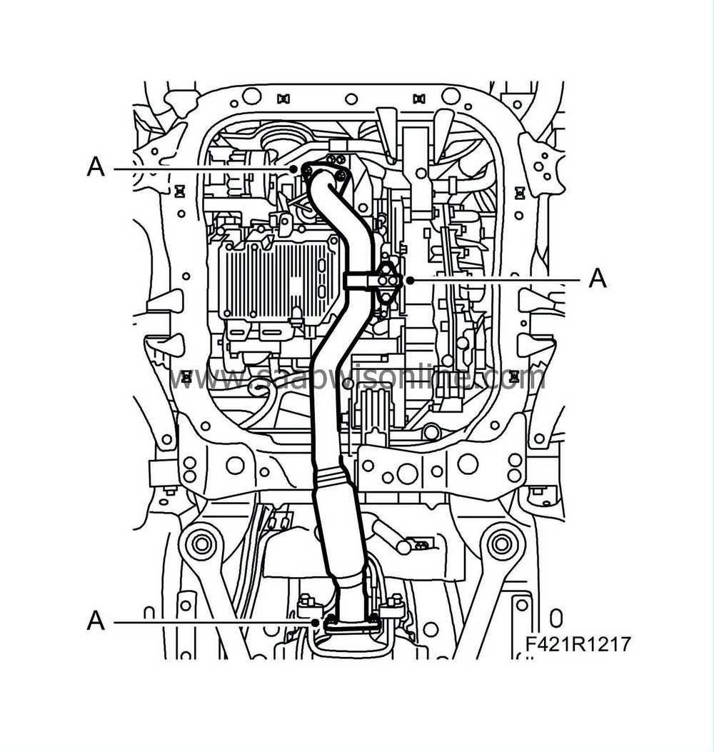
50.
|
Remove the front exhaust pipe (A).
|
|
51.
|
Fit KM 6313 Centring fixture, subframe - engine (B) on the subframe. The bracket is installed in the A/C compressor's retaining bracket. Due to narrow tolerances on the drive shafts, the centring tool must be used to carefully fit the powertrain in against the subframe and body when reinstalled.
|
|
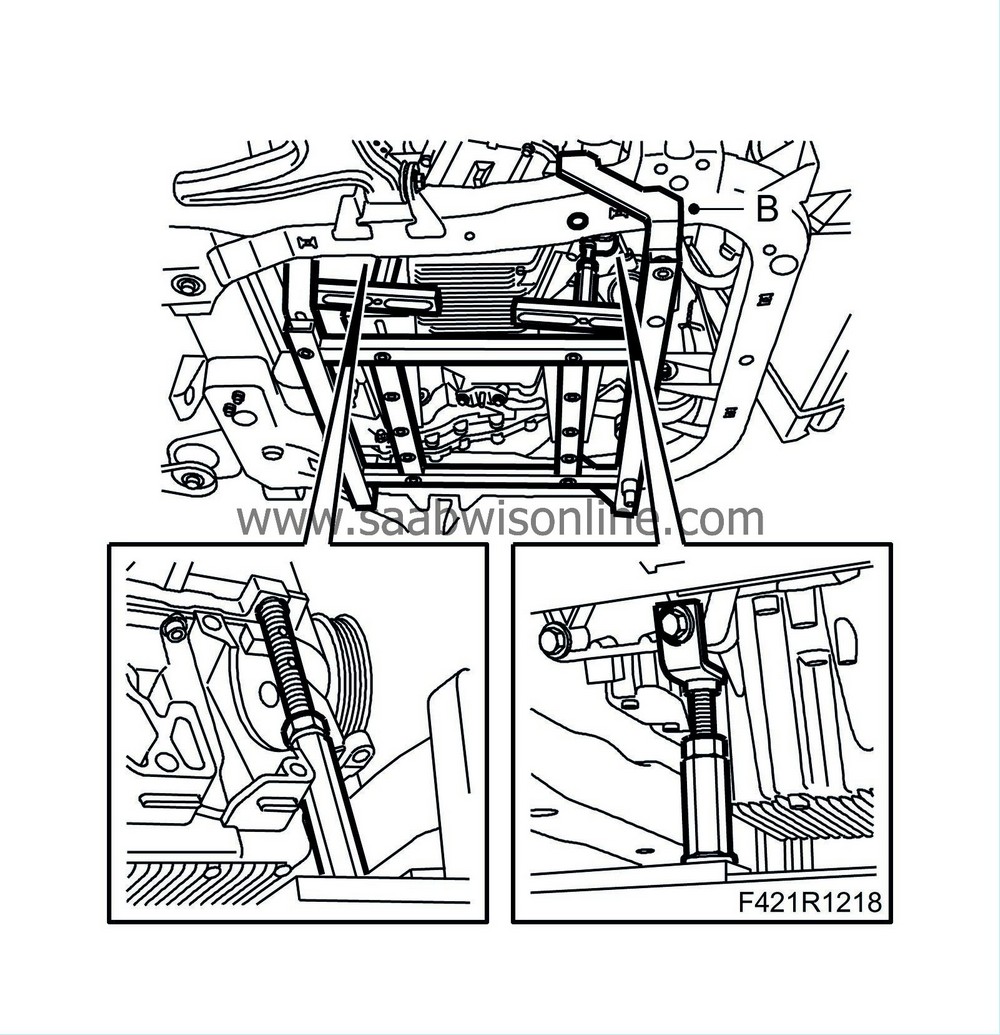
53.
|
Fit two
83 95 212 Straps
(A) to the radiator member. Lower one strap down around the radiator assembly. Wind an extra time around the A/C compressor to take the strain.
|
|
54.
|
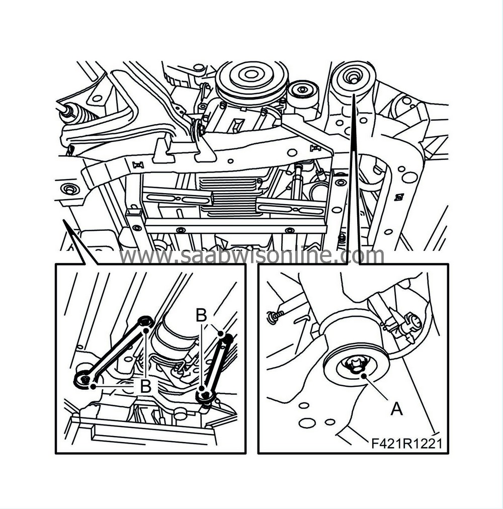
Remove the right engine pad (A).
|
|
55.
|
Remove the left engine pad (B).
|
|
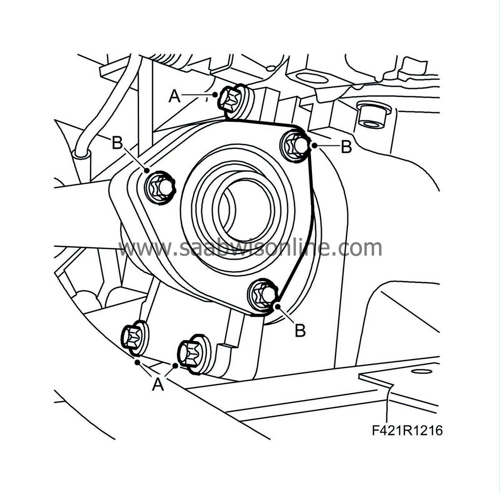
58.
|
Raise the trolley lift slightly so that it is firmly pressed against the subframe. Undo the subframe bolts (A) and subframe stay bolts (B) from the body.
|
|
59.
|
Carefully lower the power train on the trolley lift, making sure nothing gets caught or damaged.
|


