Spare part engine block, Z19 DTH, to remove
|
|
Spare part engine block, Z19 DTH, to remove
|
|
1.
|
Remove the power unit, see Power train removal.
|
|
3.
|
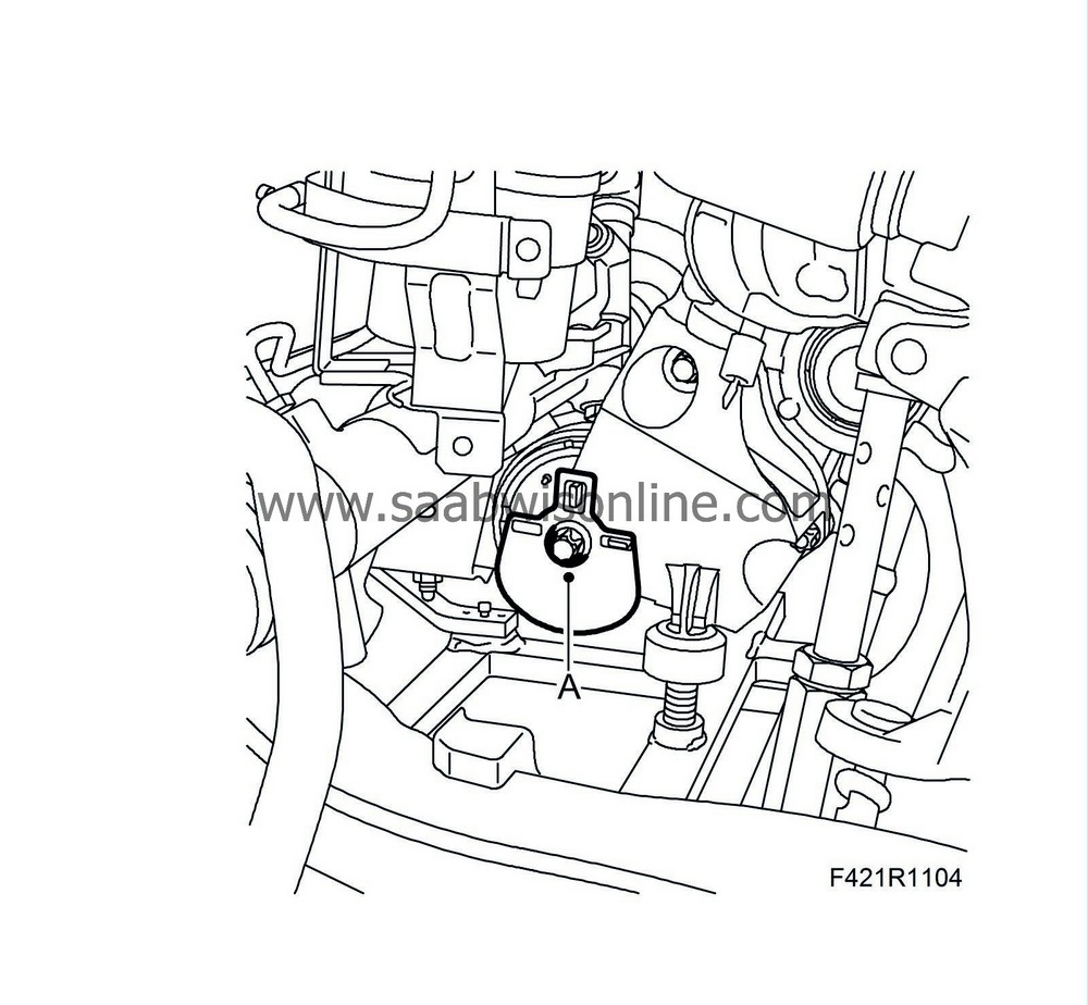
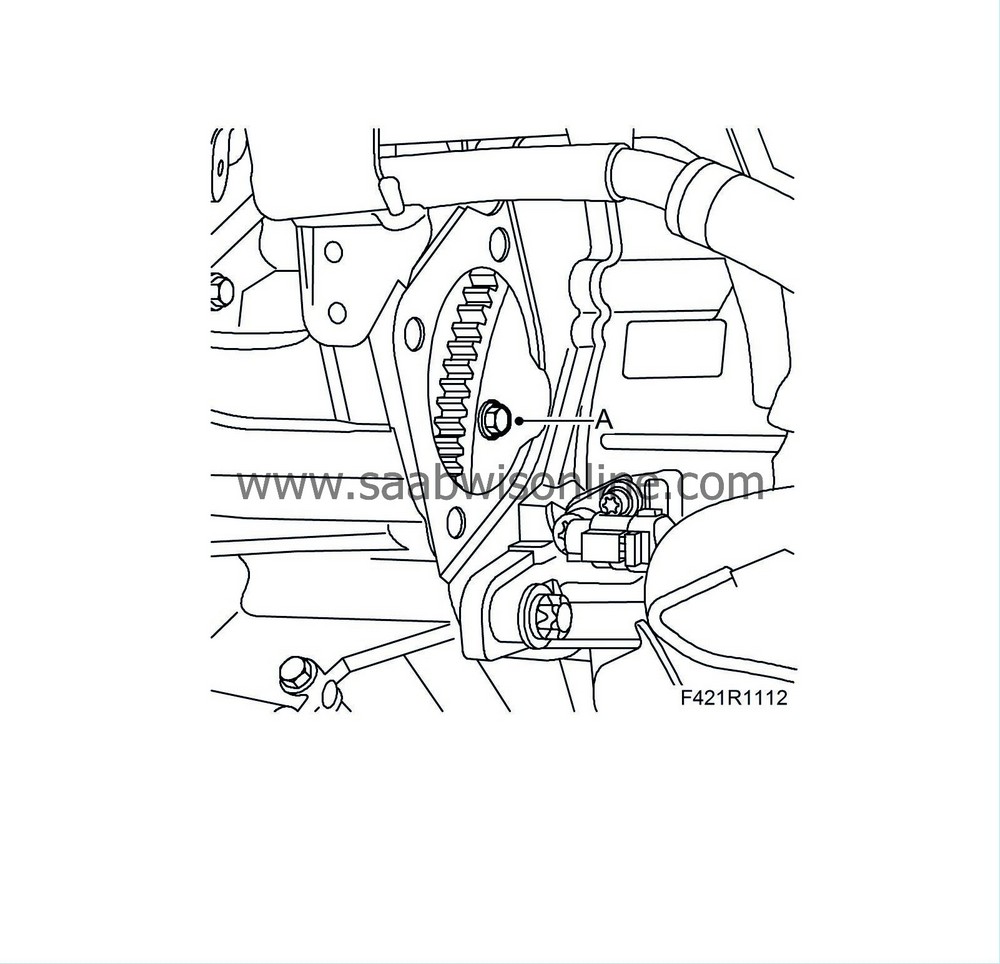
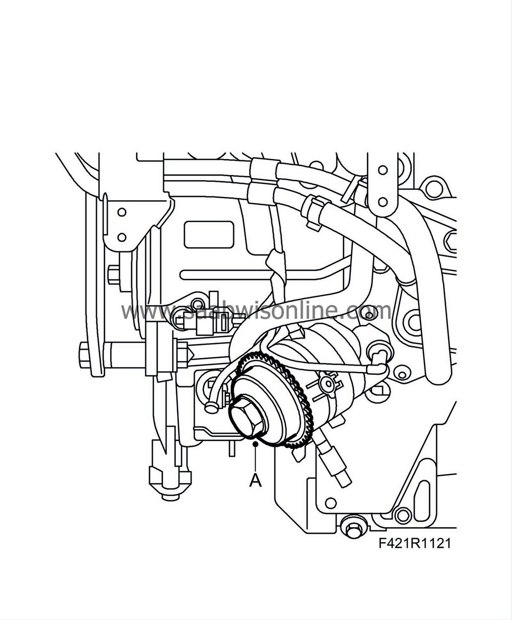
Remove the electrical connections from the EHPS unit (A).
|
|
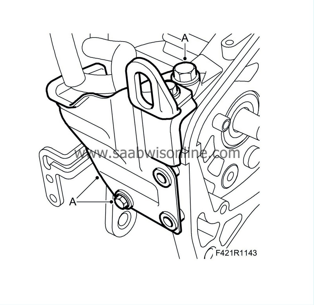
4.
|
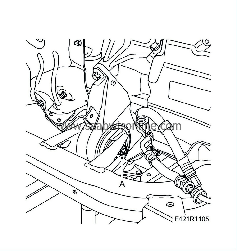
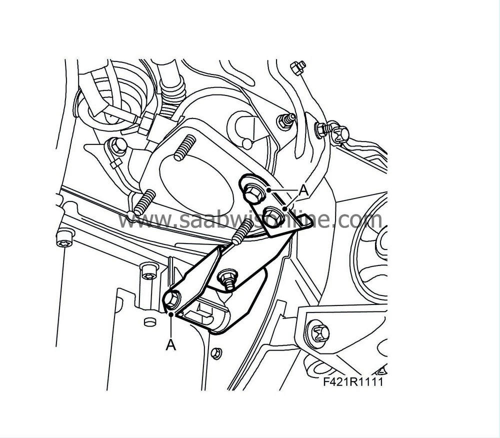
Remove the rear torque arm (A) from the subframe.
|
|
5.
|
Remove the front torque arm (A) from the subframe.
|
|
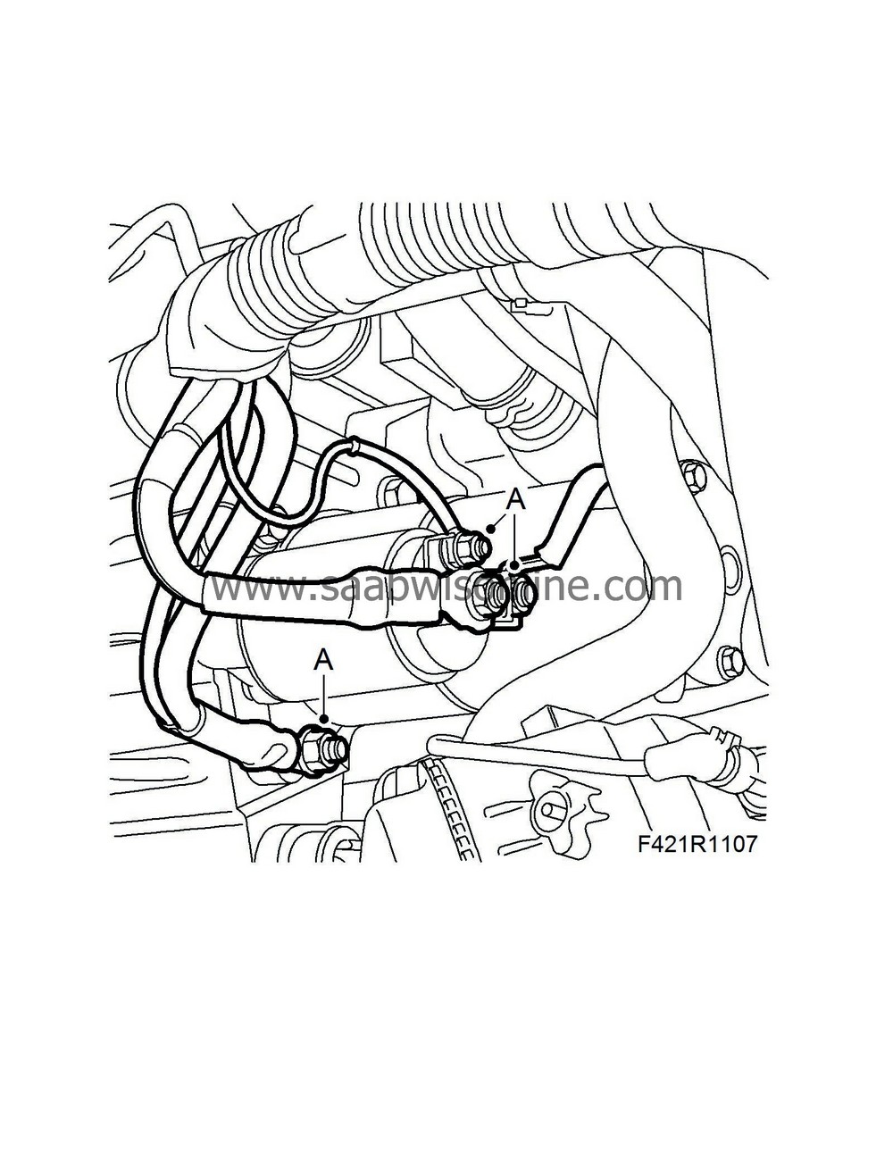
7.
|
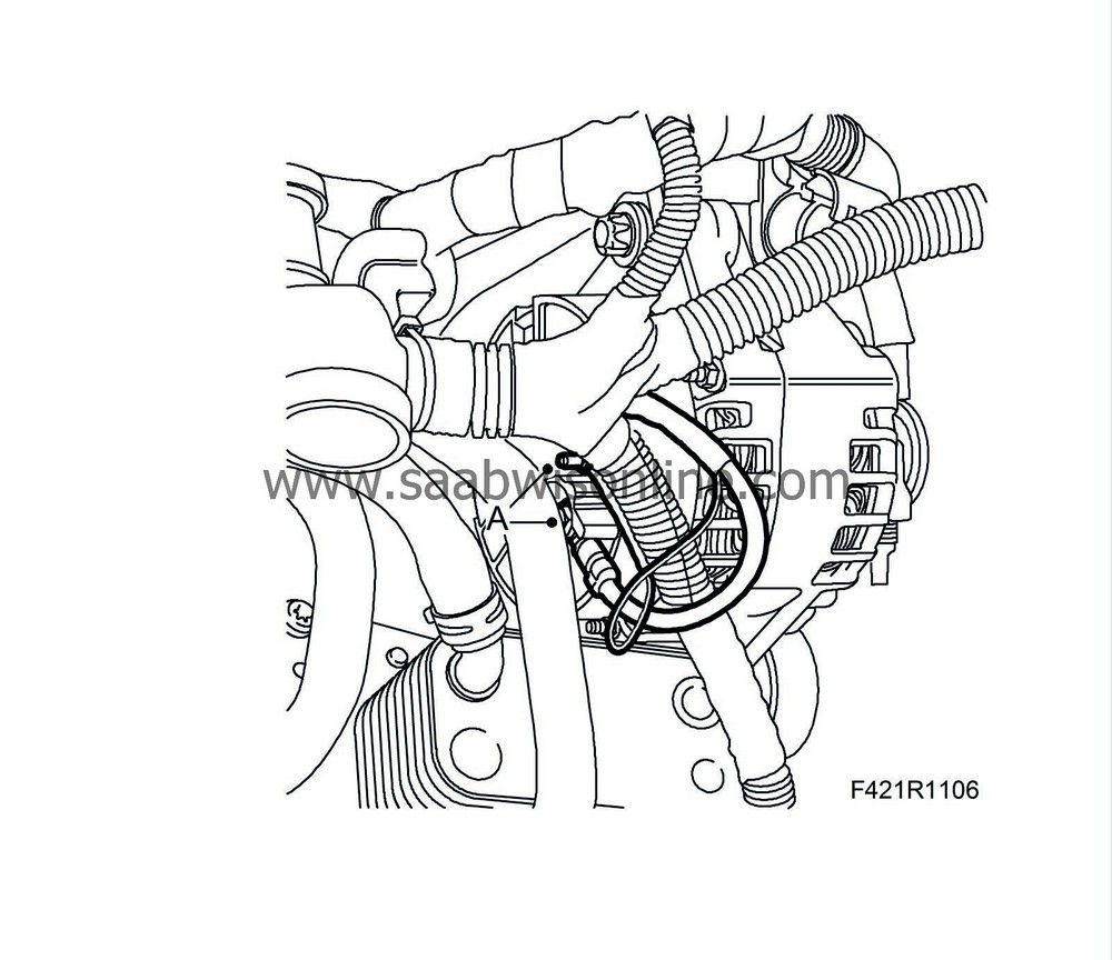
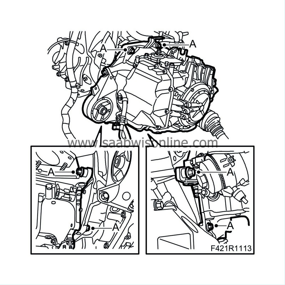
Remove the electrical connections from the alternator (A).
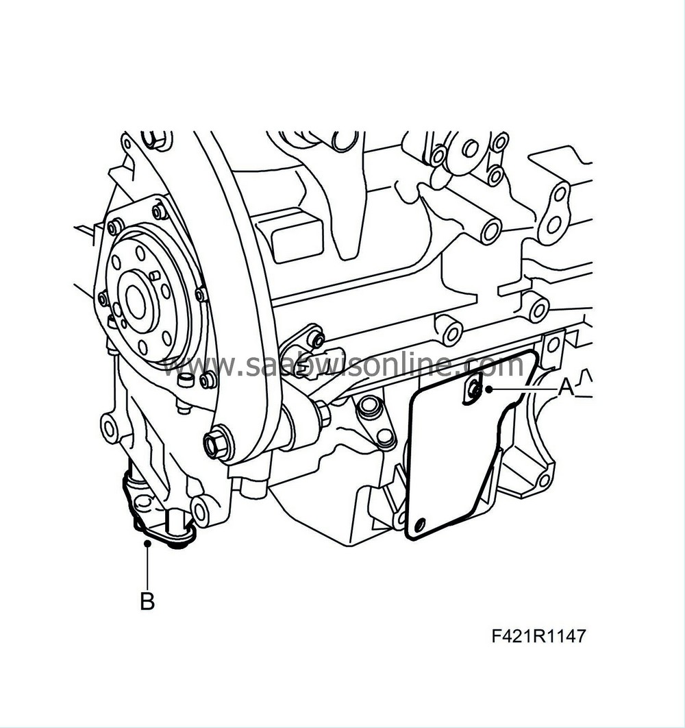
|
|
8.
|
Remove the electrical connections from the starter motor (A).
|
|
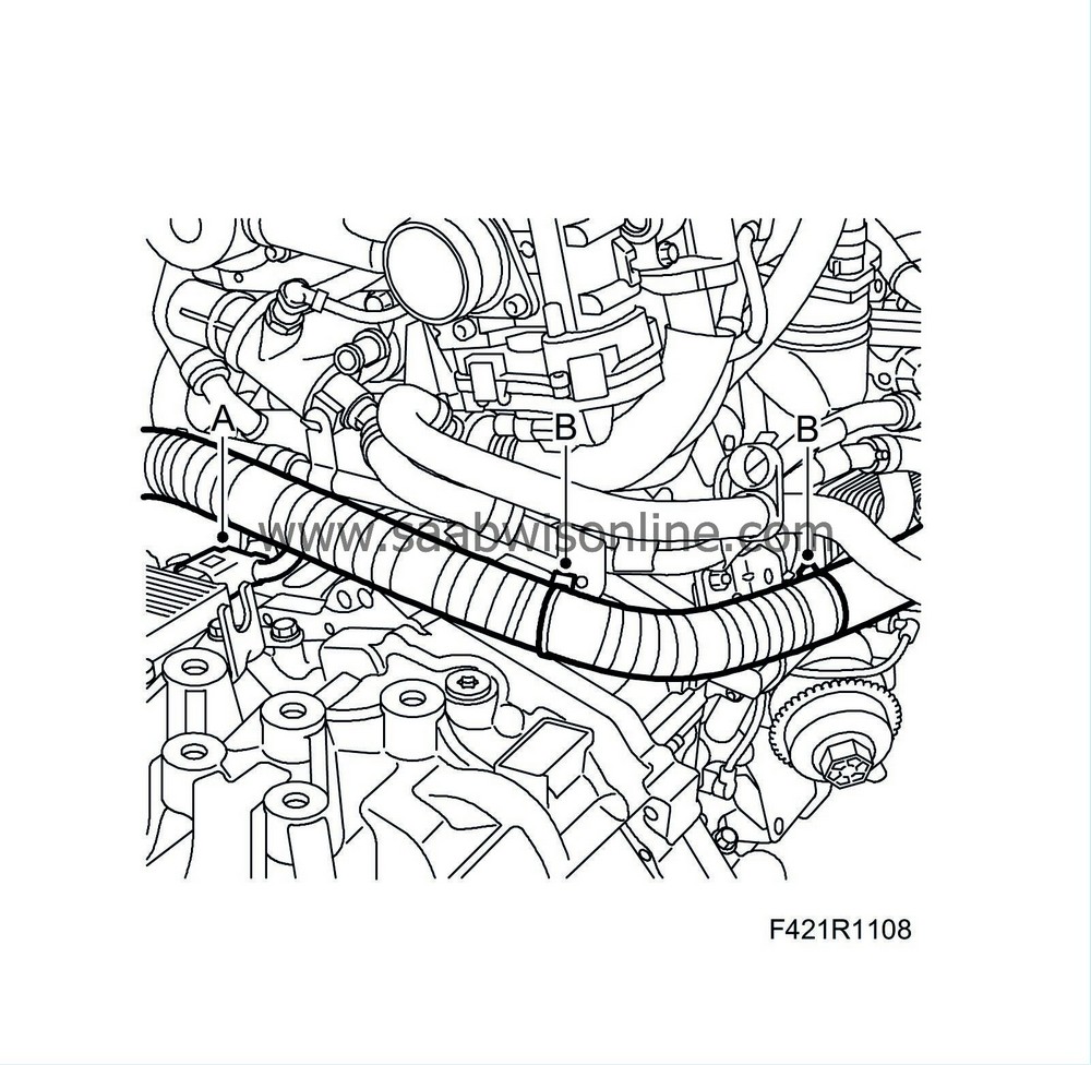
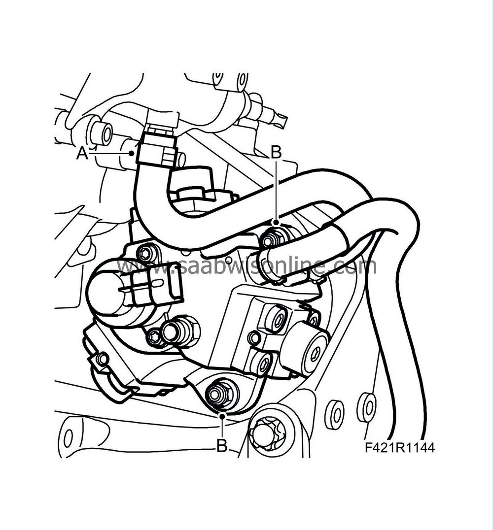
9.
|
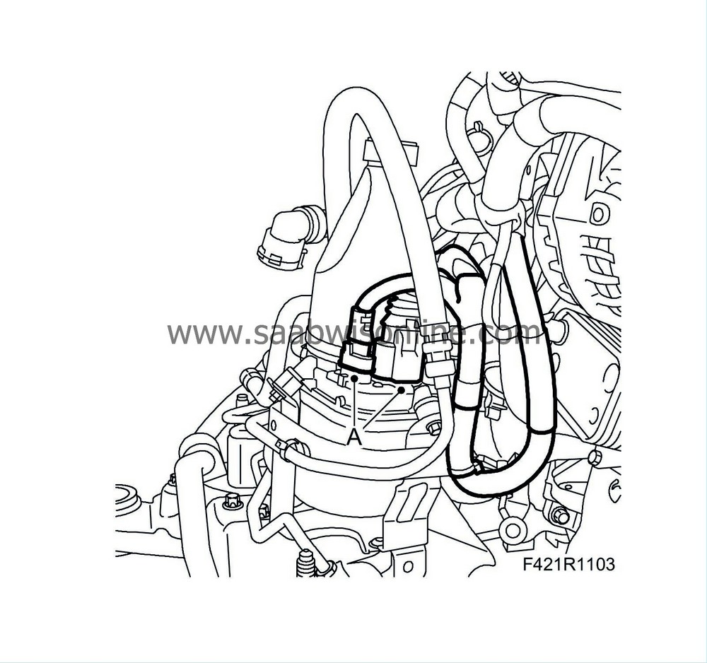
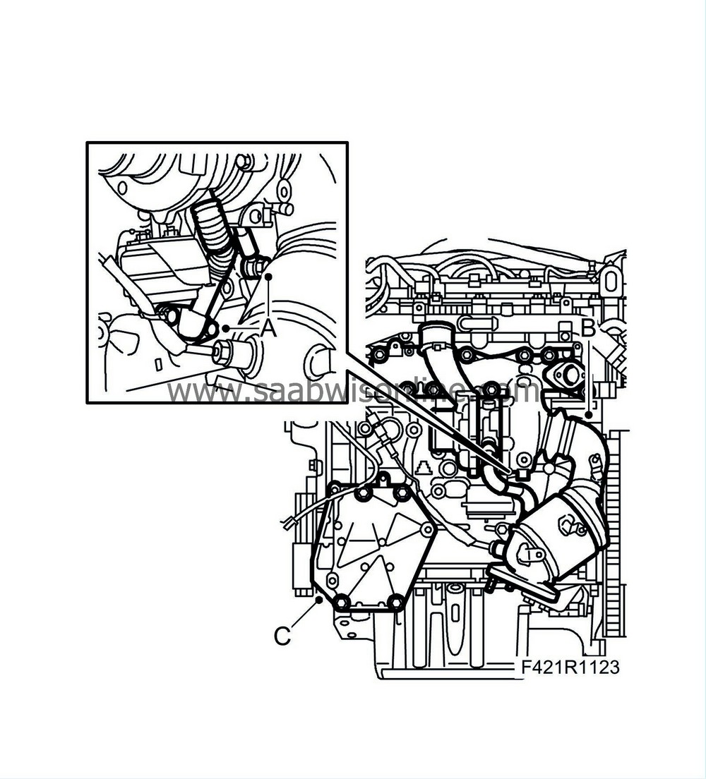
Unplug the connector for the TCM (A) and undo the clips (B).
|
|
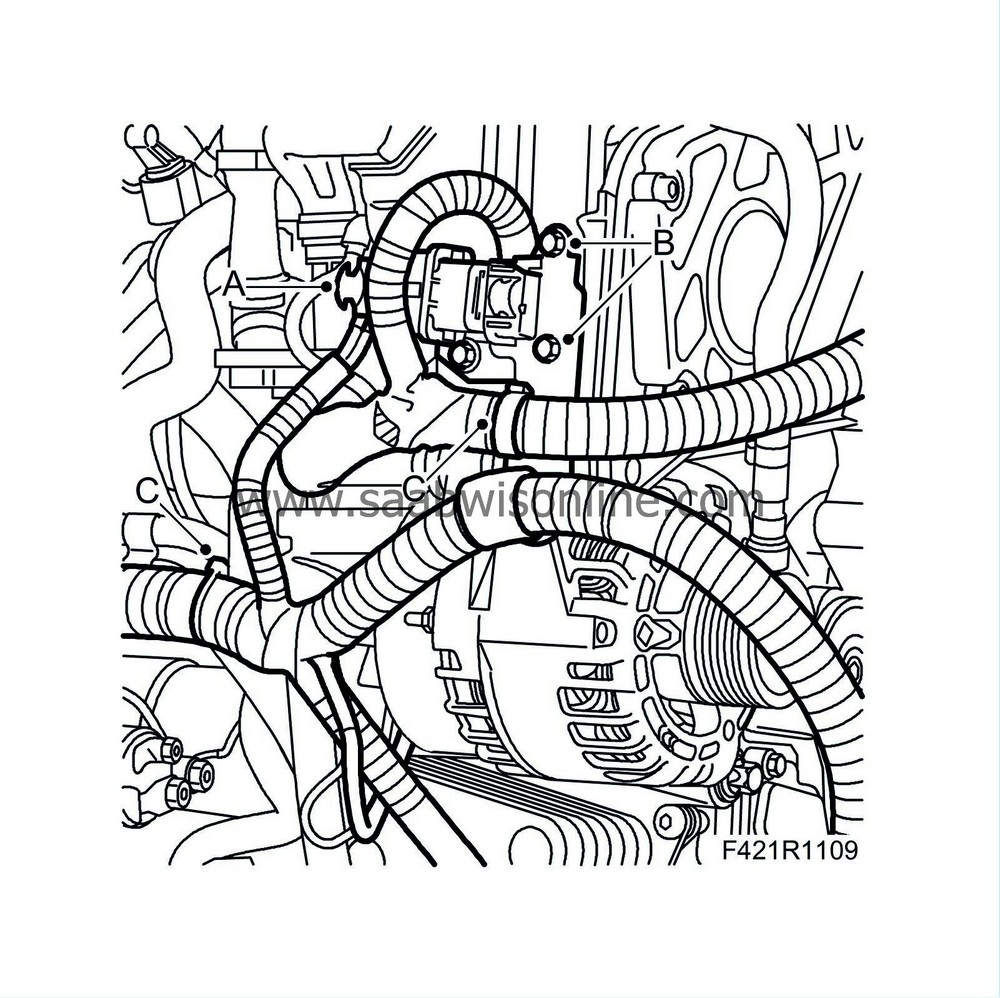
10.
|
Unplug the engine harness connector (A), remove the bracket (B) and clip (C).
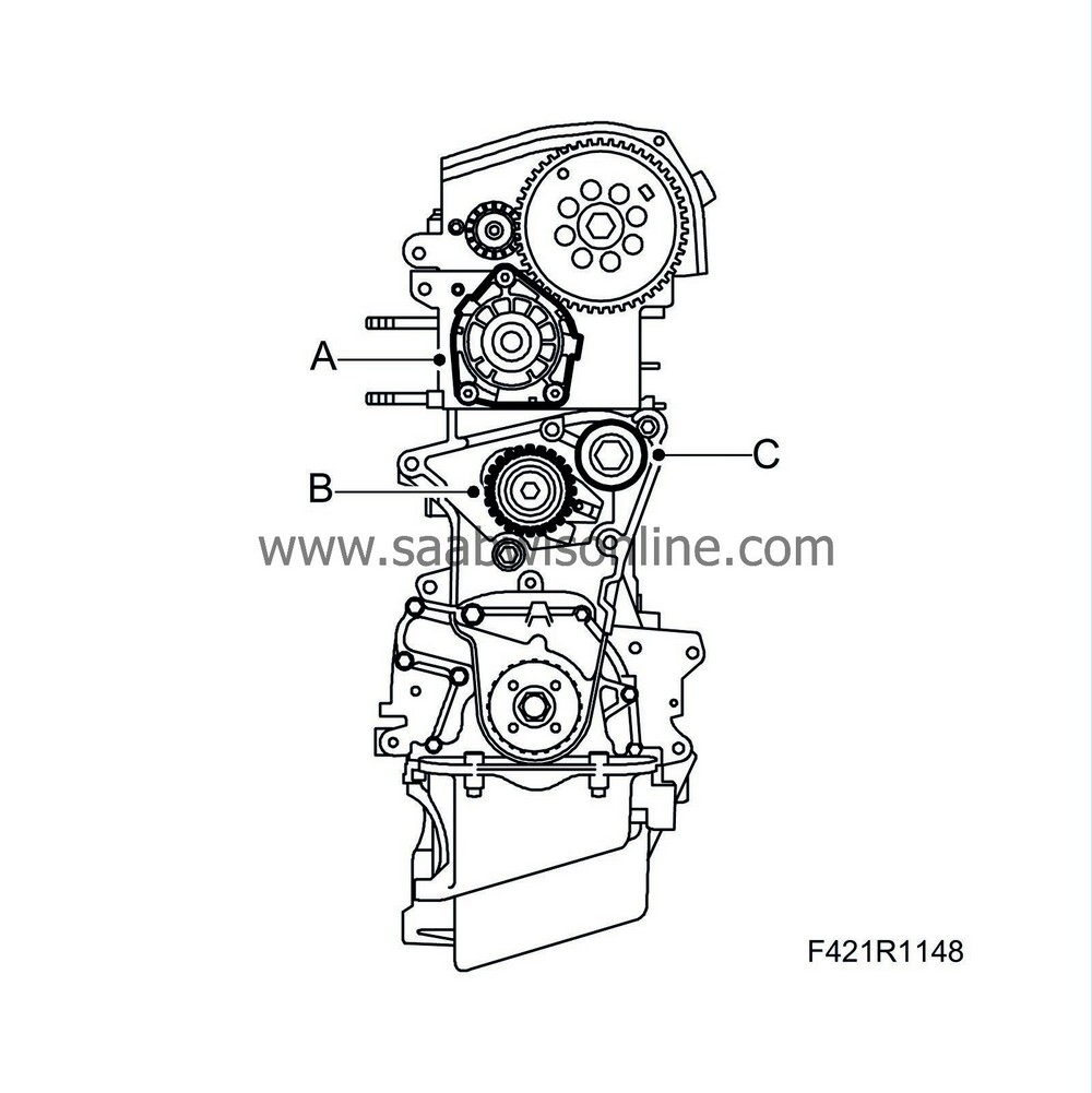
|
|
11.
|
Remove the wiring harness from the engine.
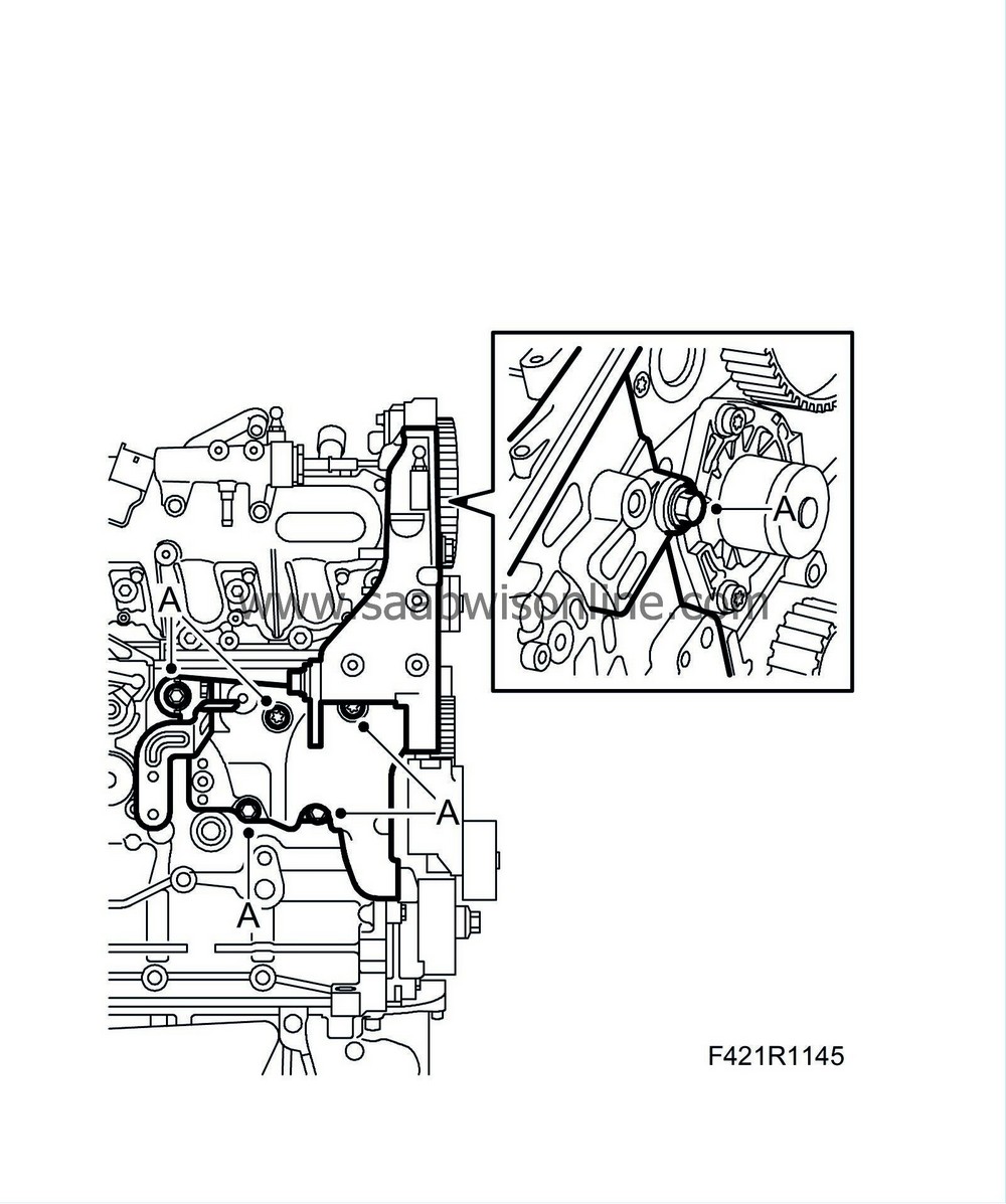
|
|
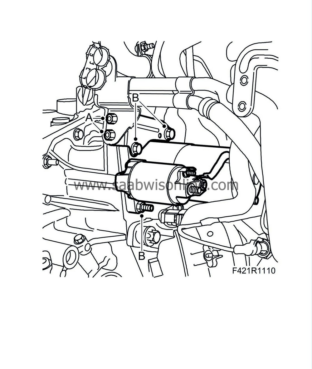
12.
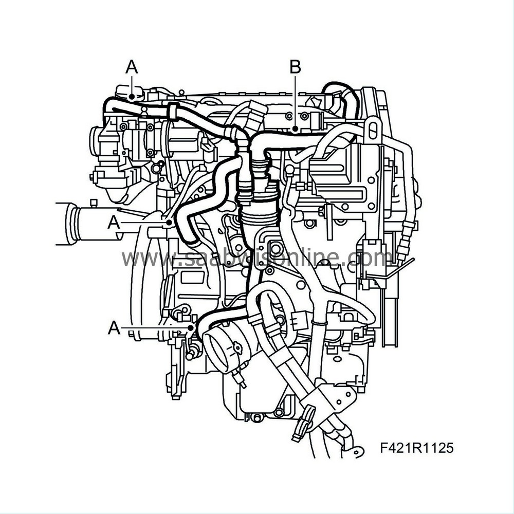
|
Remove the cable mounting (A) located on the coolant pipes/starter motor. Remove the starter motor (B).
|
|
13.
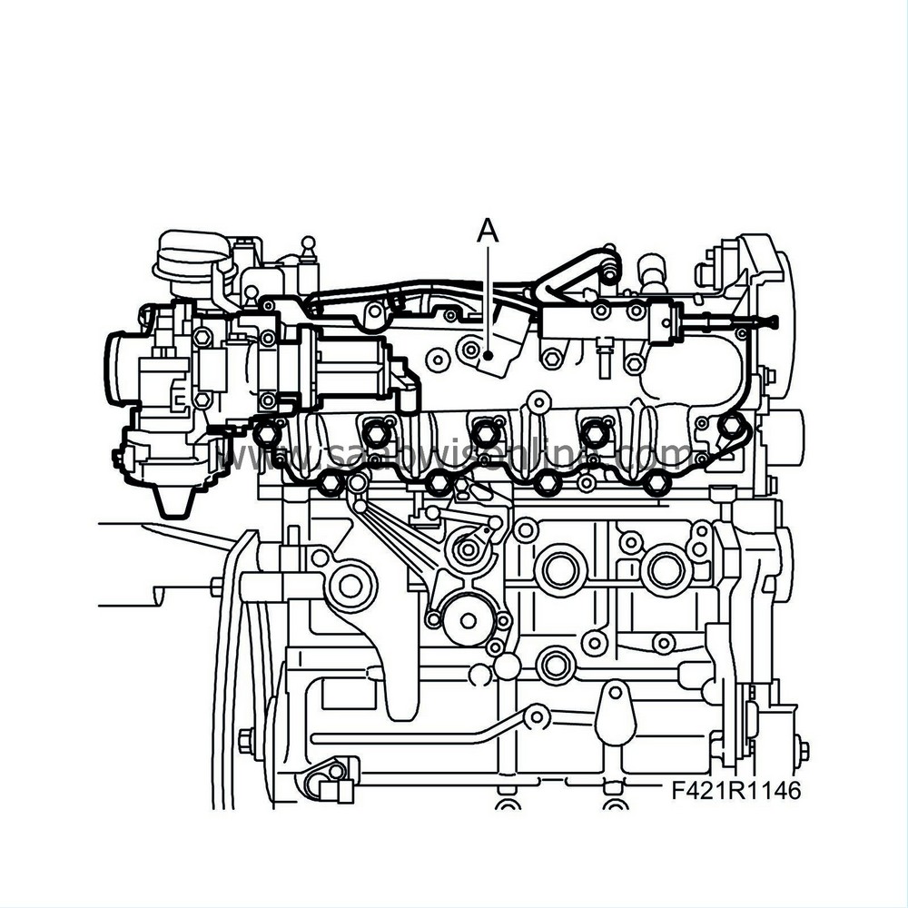
|
Raise the unit for better access.
|
|
14.
|
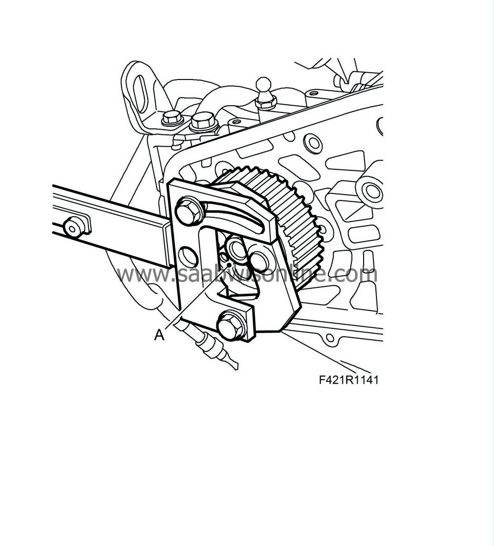
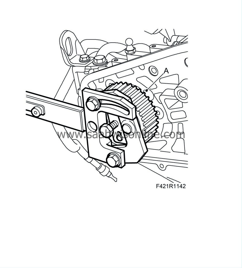
Remove the front catalytic converter bracket (A).
|
|
15.
|
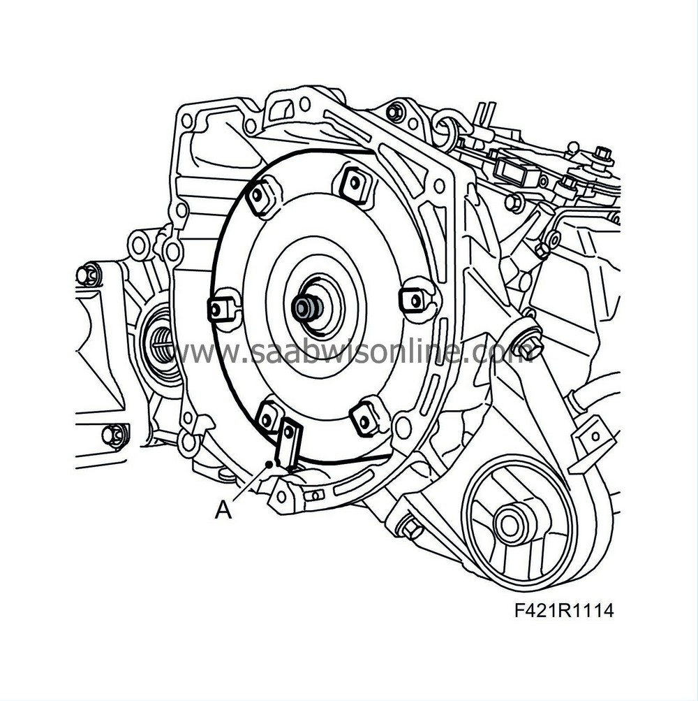
Aut
: Undo the 6 bolts (A) holding the torque converter to the driver plate. Rotate the engine clockwise on the pulley centre bolt.
|
|
16.
|
Man
: Remove the gearbox bolts and lift it away from the engine.
|
|
17.
|
Aut
: Remove the gearbox bolts (A). Pull out the gearbox about 10 mm.
|
|
18.
|
Undo the plug and press the torque converter against the gearbox, fit
87 92 574 Holder
for holding the torque converter in place and remove the gearbox (A).
|
|
19.
|
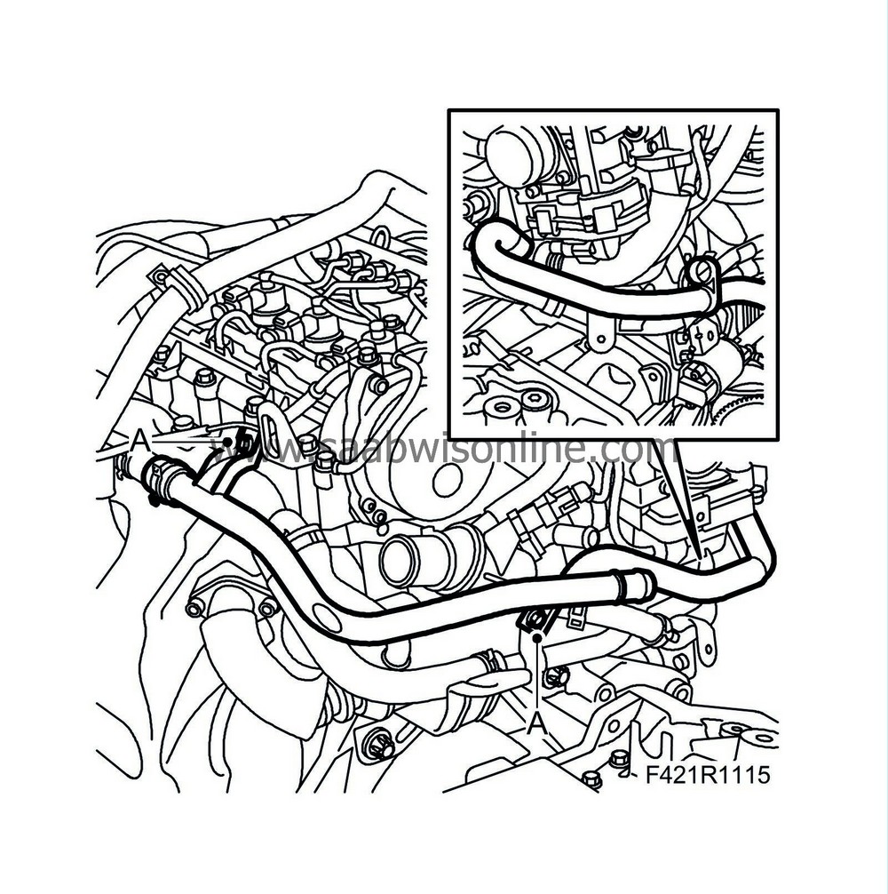
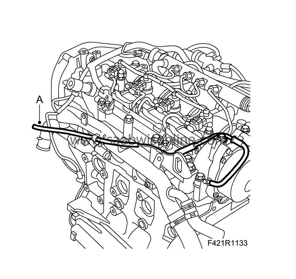
Remove the pipe (A) to the coolant reservoir.
|
|
20.
|
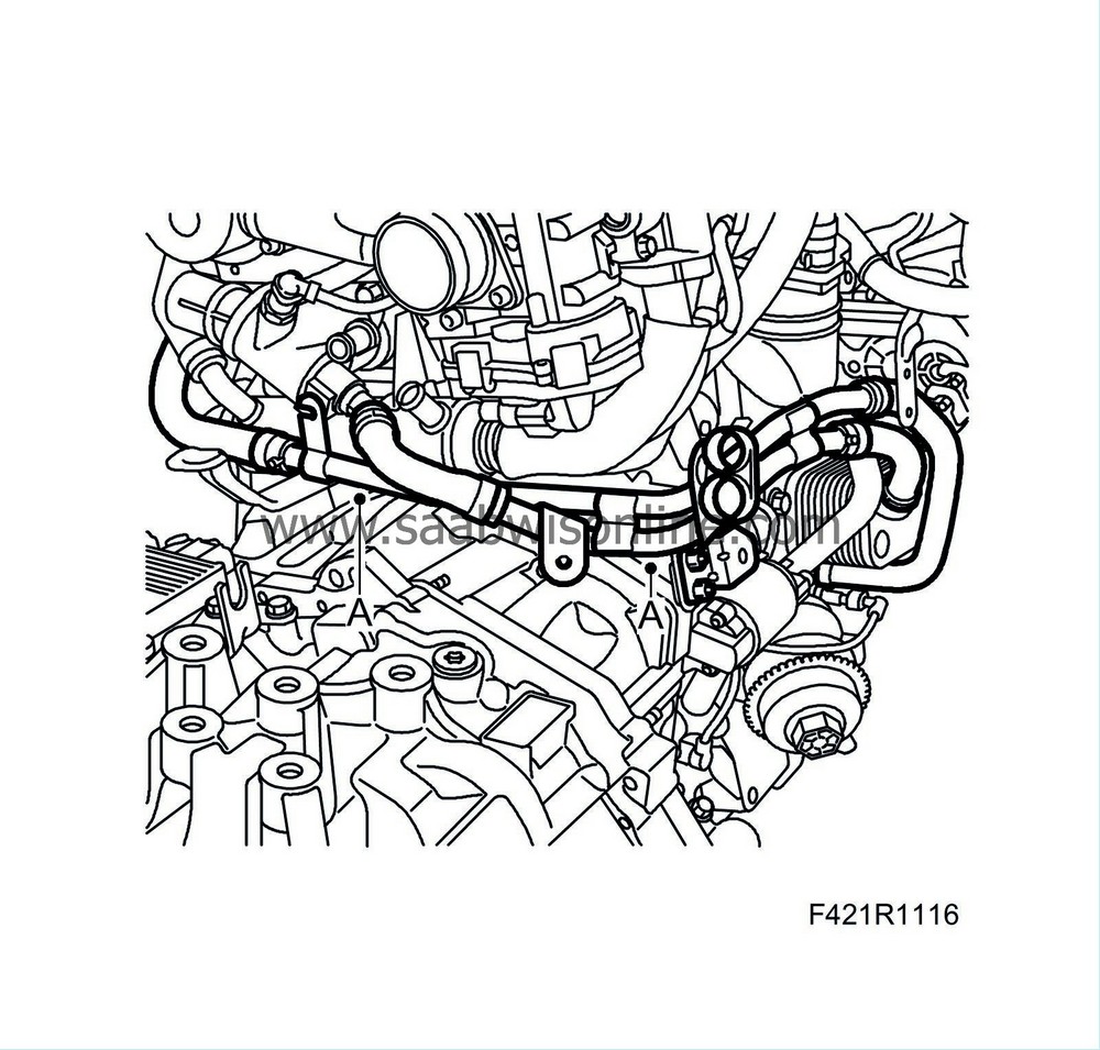
Remove the coolant pipes (A) leading to the oil cooler.
|
|
21.
|
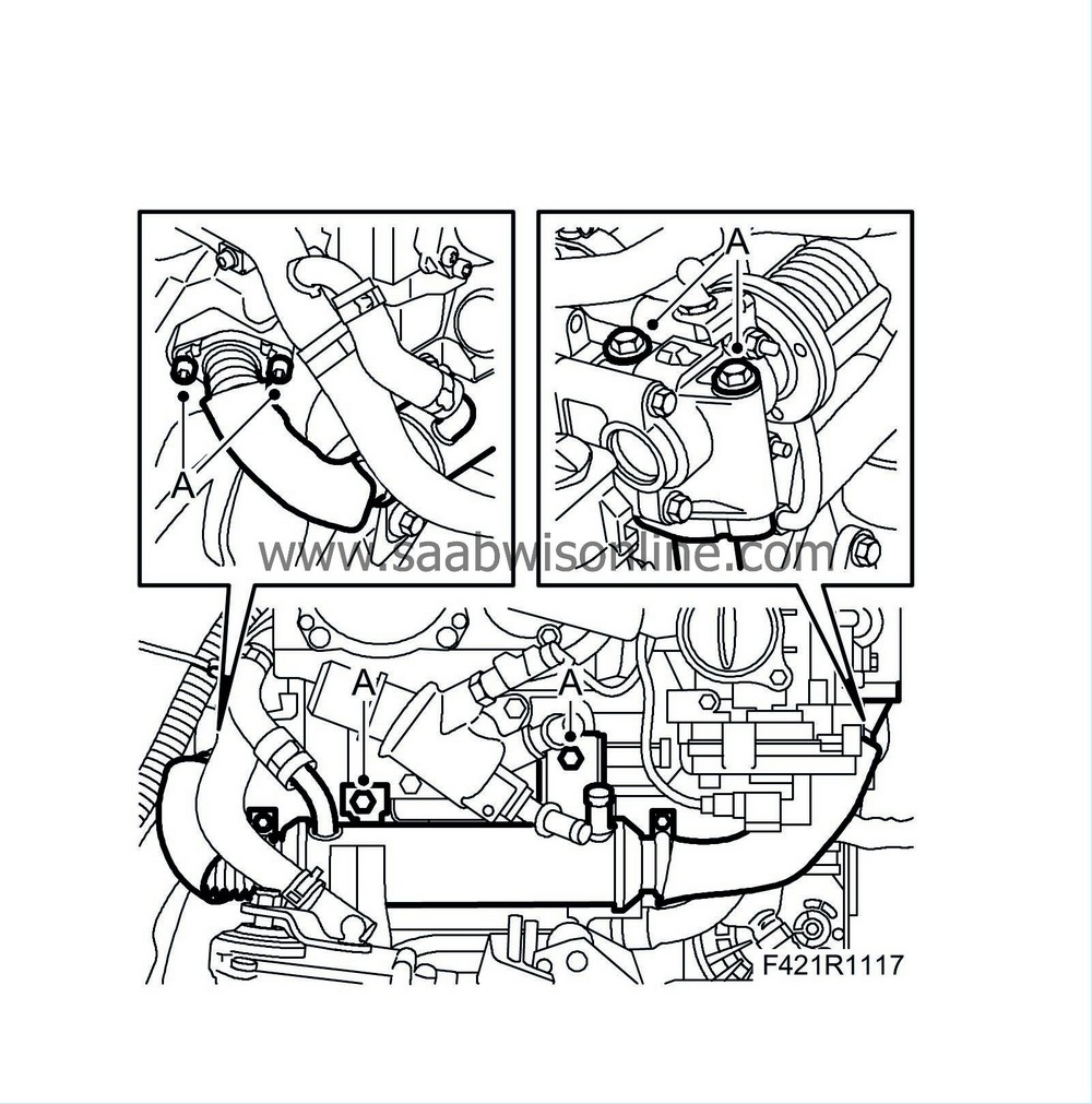
Remove the EGR cooler (A) assembly.
|
|
23.
|
Man
: Remove the bolts holding the pressure plate and remove the clutch.
|
|
24.
|
Man
: Remove the clutch plate.
|
|
25.
|
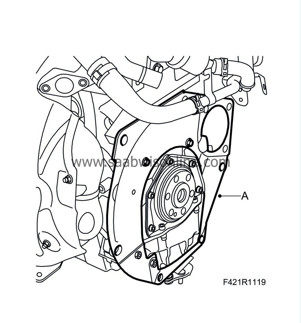
Remove the flywheel/driver plate (A).
|
|
26.
|
Remove the flywheel locking attachment (B).
|
|
27.
|
Remove the protective plate.
|
|
29.
|
Drain the engine oil and remove the oil filter cap and the filter.
|
|
30.
|
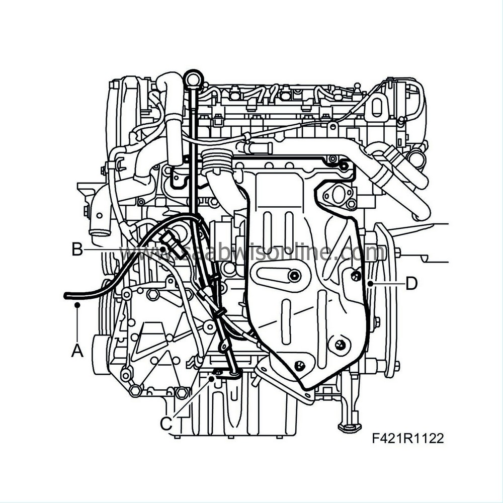
Undo the vacuum hose (A) from the diaphragm box.
|
|
31.
|
Remove the bracket for the temperature sensor's connector:
|
|
|
-
|
Unplug the connector (B)
|
|
|
-
|
Detach the cable from the clip
|
|
|
-
|
Remove the connector's bracket (B)
|
|
32.
|
Remove the dipstick pipe (C).
|
|
33.
|
Remove the heat shield (D)
|
|
34.
|
Remove the turbocharger oil delivery line and return line from the engine block. (A)
|
|
35.
|
Remove the turbo from the catalytic converter (B).
|
|
36.
|
Remove the AC bracket (C).
|
|
37.
|
Remove the alternator (A).
|
|
38.
|
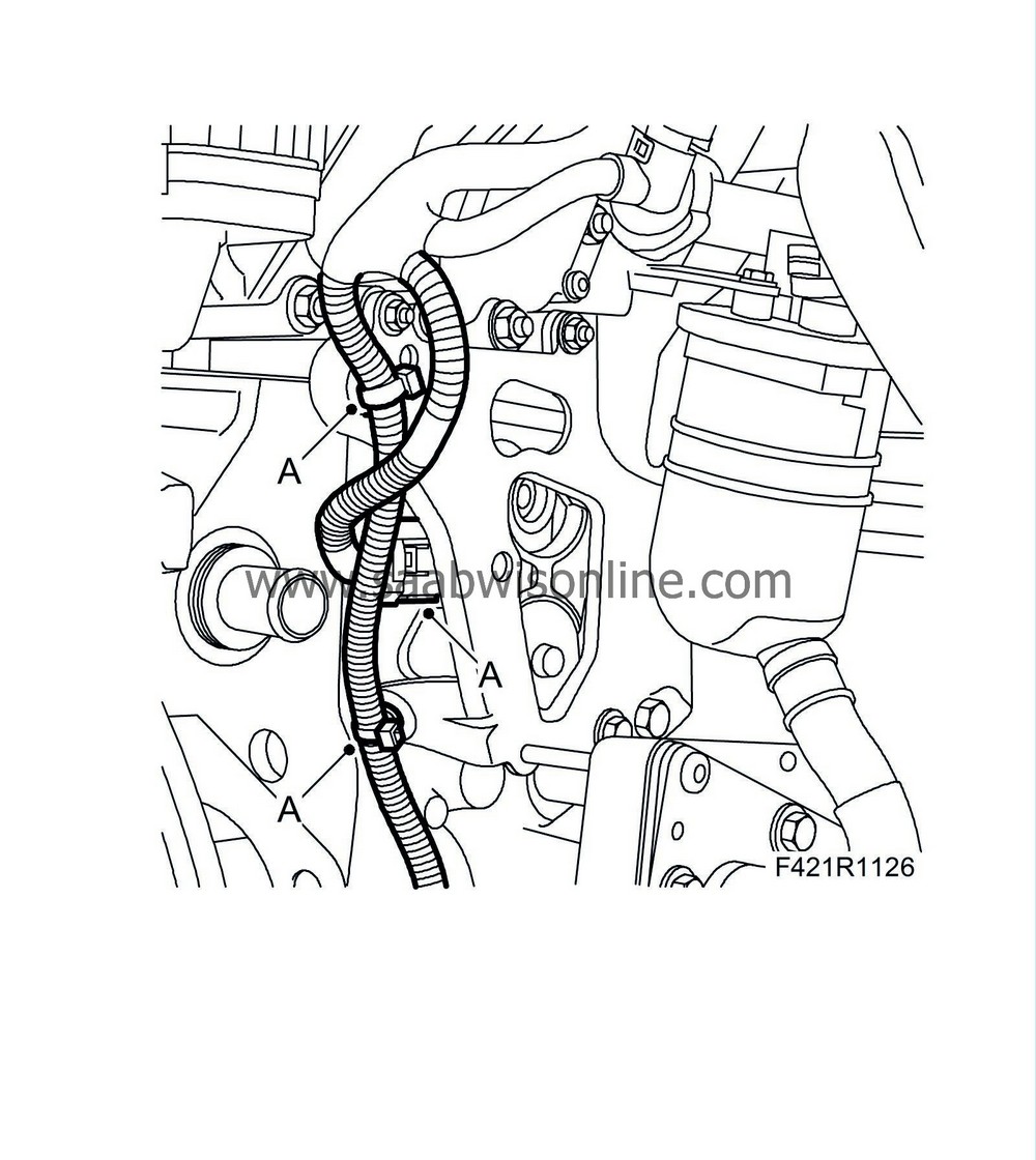
Remove the crankcase ventilation hoses from the engine, the oil sump and the oil filler connection pipe. Open the hose's clip. (A)
|
|
39.
|
Remove the oil trap hose with quick coupling (B).
|
|
40.
|
Undo the wiring harness from the bracket and unplug the combustion circulation connector.
|
|
41.
|
Open the wiring harness clip (A).
|
|
42.
|
Remove the bracket for the oil separator.
|
|
43.
|
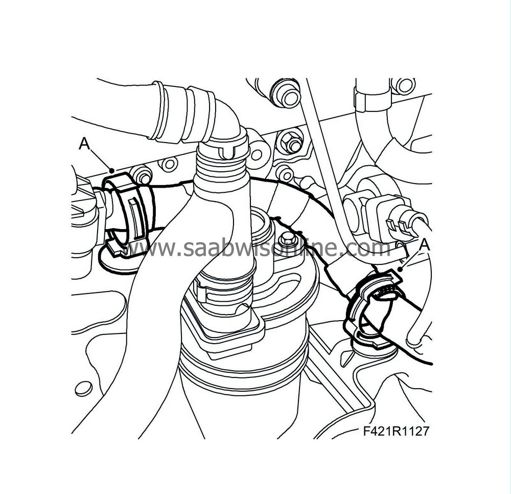
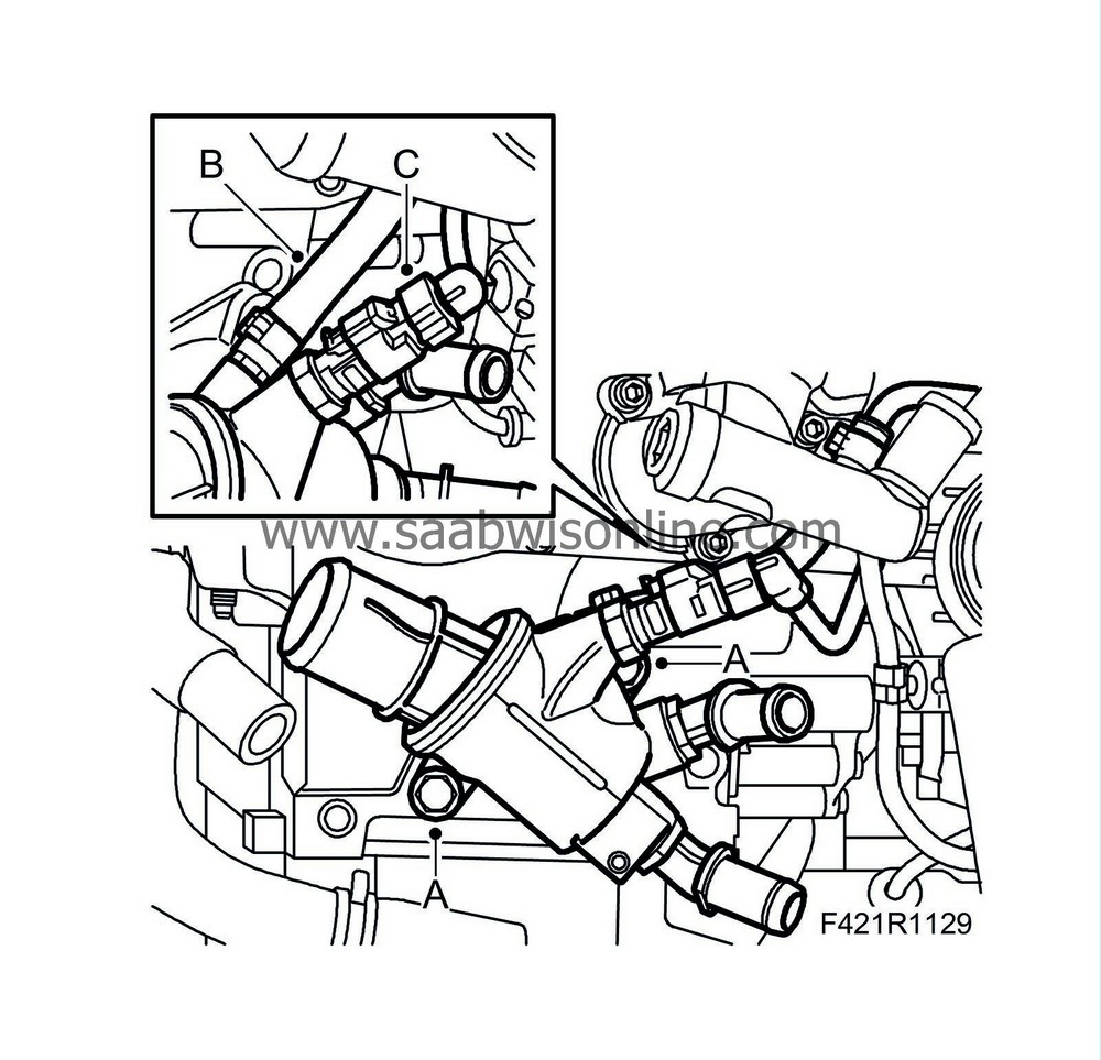
Remove the thermostat housing:
|
|
|
-
|
Remove the bolts (A)
|
|
|
-
|
Remove the hose from the thermostat housing (B)
|
|
|
-
|
Unplug the connector (C)
|
|
44.
|
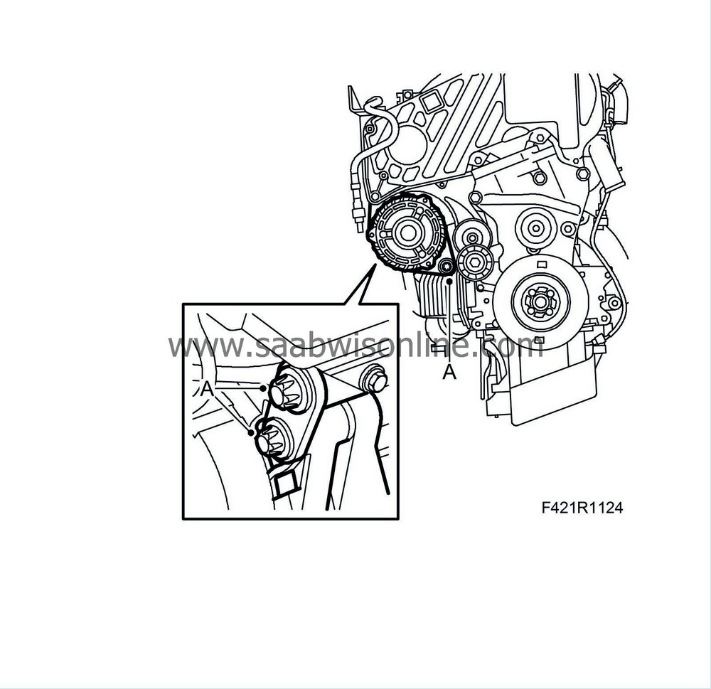
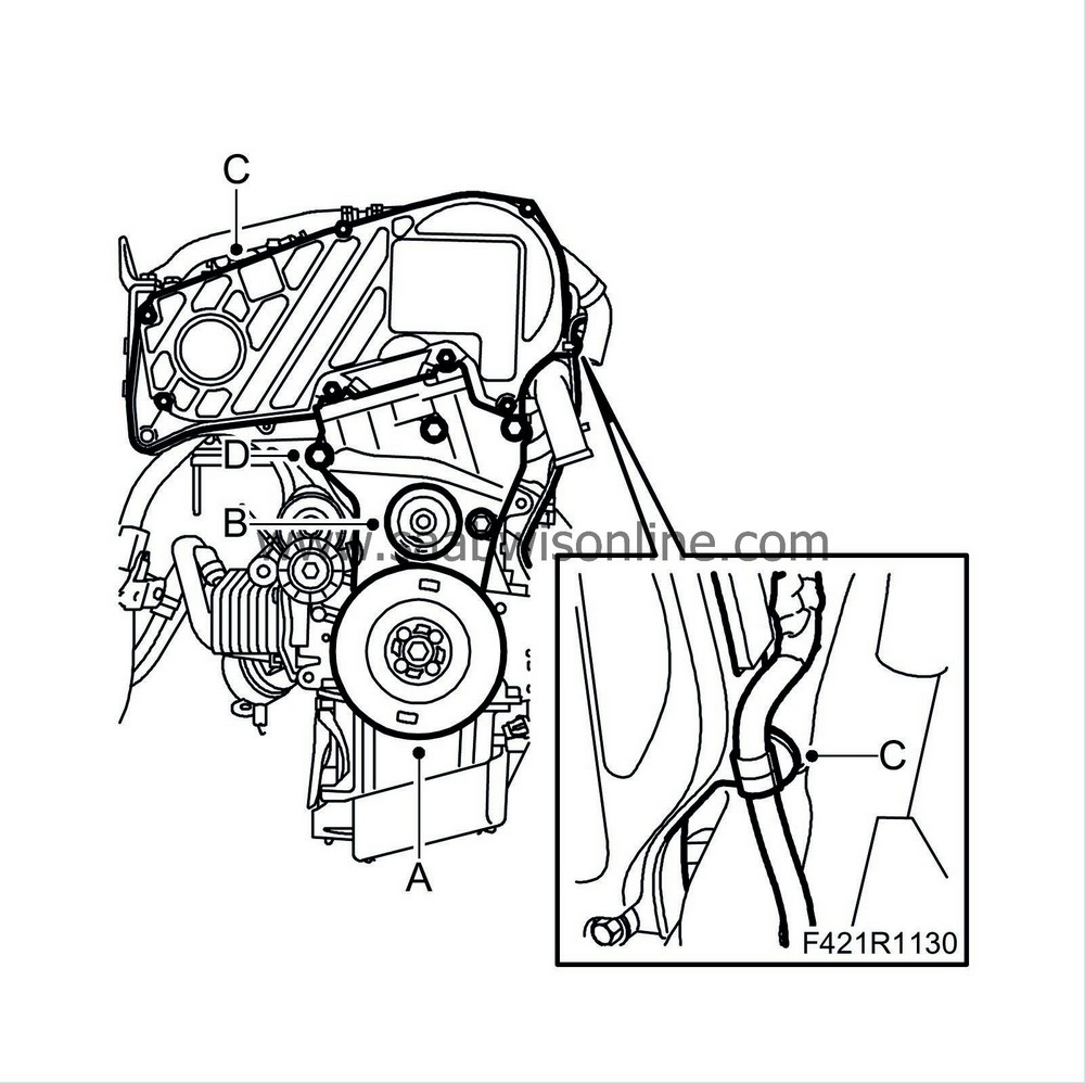
Remove the crankshaft pulley (A).
|
|
45.
|
Remove the idler pulley centre bolt on the lower timing cover (B). Use, for example, 2 screwdrivers to carefully prize off from two directions.
|
|
46.
|
Remove the upper timing cover (C).
|
|
47.
|
Remove the lower timing cover (D).
|
|
48.
|
Undo the crankcase ventilation pipe and hose form the camshaft housing.
|
|
49.
|
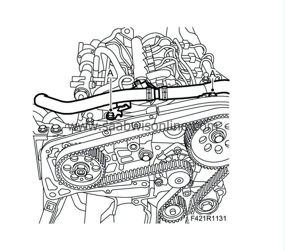
Reset the engine by removing the plug and fitting
32 025 008 Camshaft fixing tool
(A). Turn the engine until the tool clicks and locks the exhaust camshaft.
|
|
50.
|
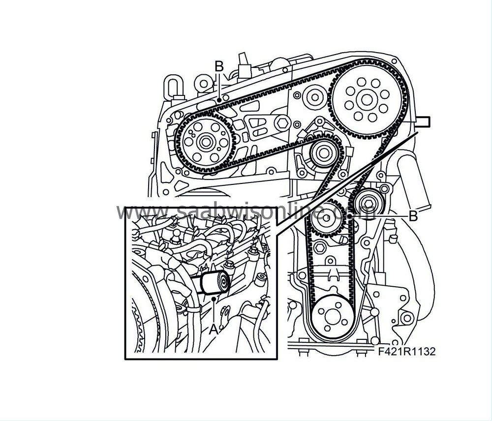
Relieve tension in the belt tensioner and remove the timing belt (B). Mark the direction of rotation if the timing belt is to be refitted.
|
|
51.
|
Remove the vacuum line from the cable jointing chamber.
|
|
52.
|
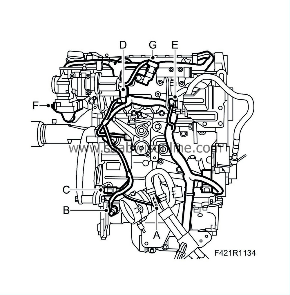
Remove the engine wiring harness by unplugging the following connectors:
|
|
|
-
|
Pressure switch, engine oil (44) (A)
|
|
|
-
|
Level sensor, engine oil (243) (B)
|
|
|
-
|
Crankshaft position sensor (345) (C)
|
|
|
-
|
EGR solenoid valve (606) (D)
|
|
|
-
|
Fuel quantity control valve, high-pressure pump (652b) (E)
|
|
|
-
|
Throttle body actuator unit (604) (F)
|
|
|
-
|
Intake air sensor (688) (G)
|
|
|
-
|
Camshaft position sensor (555) (H)
|
|
|
-
|
Fuel pressure sensor (653) (J)
|
|
|
-
|
Fuel pressure control valve (652a) (K) (certain cars)
|
|
|
-
|
Glow plug connector (L)
|
|
53.
|
Remove the cable duct.
|
|
54.
|
Lift off the wiring harness.
|
|
55.
|
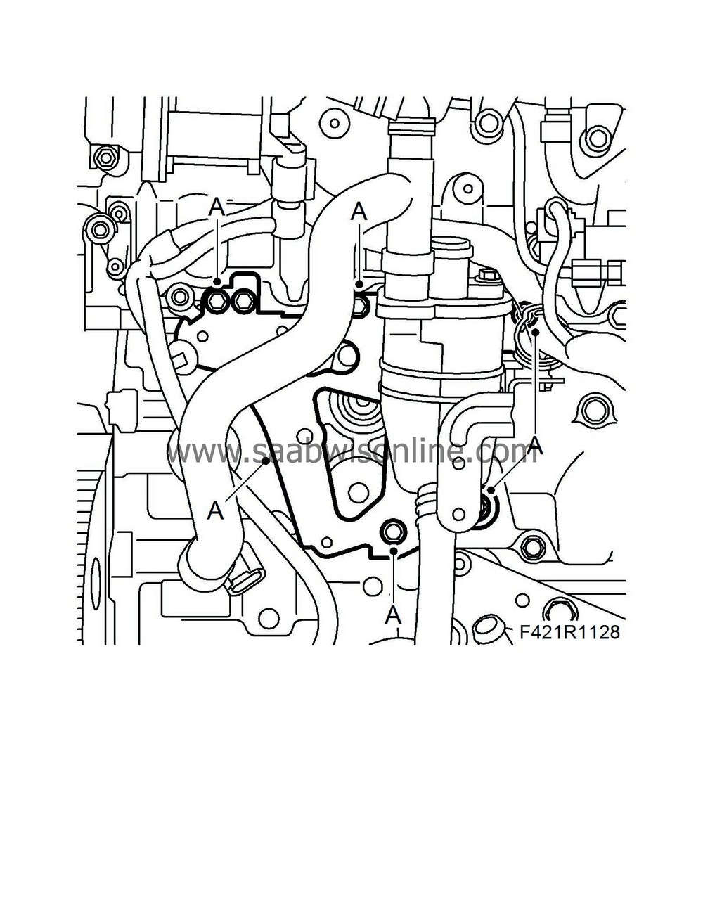
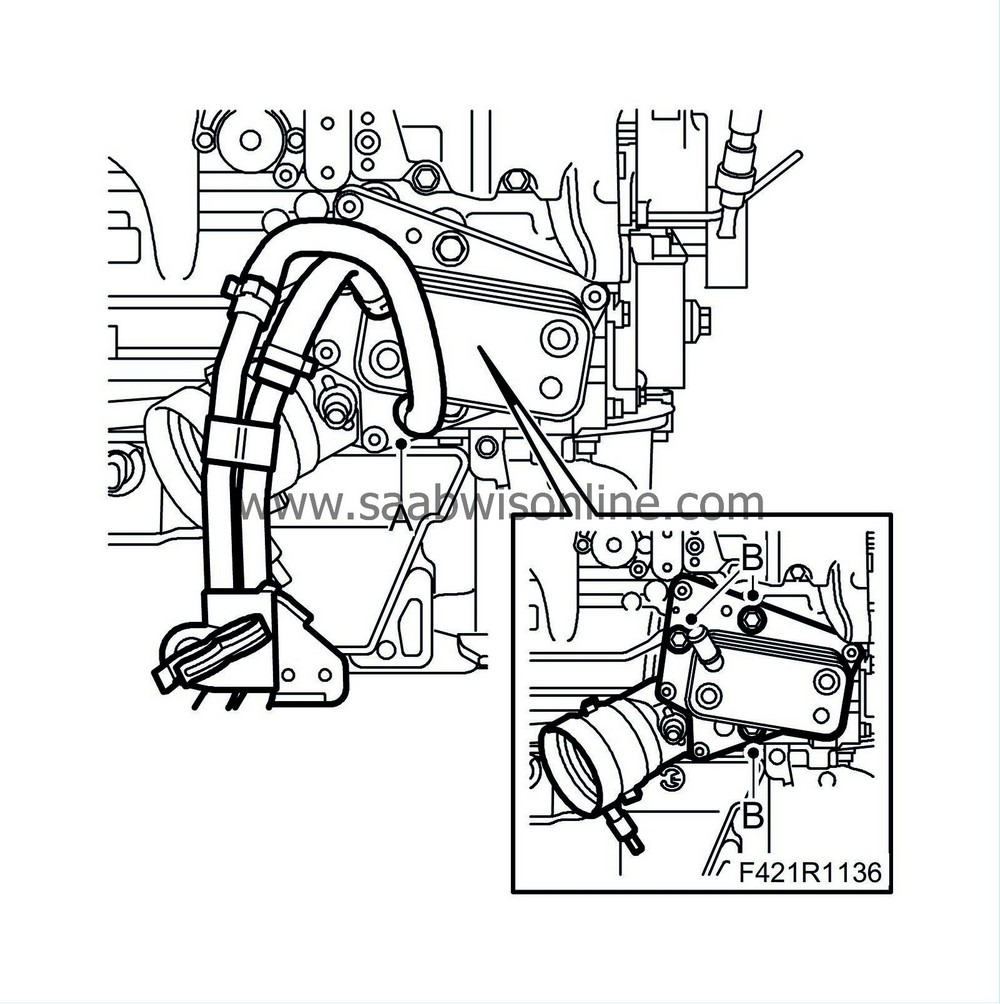
Remove the oil cooler:
|
|
|
-
|
Detach the lower coolant connection to the oil cooler (A).
|
|
|
-
|
Remove the oil cooler (B).
|
|
56.
|
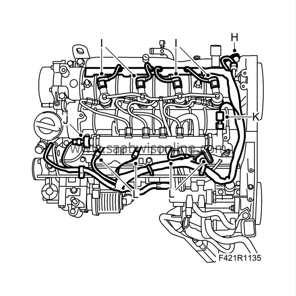
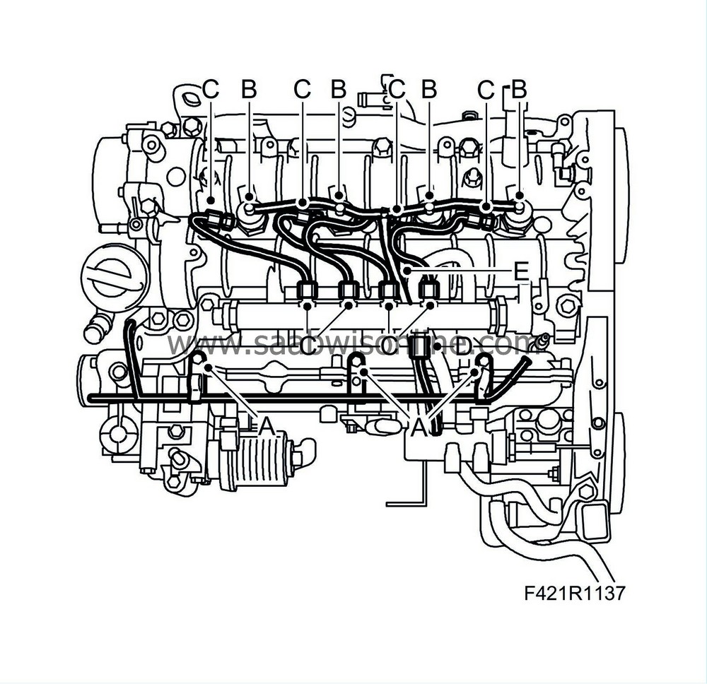
Remove the coolant pipe on the intake manifold (A)
|
Important
|
|
The return line must not be removed from the fuel return's damping housing. Otherwise it must be replaced.
|
|
|
|
|
57.
|
Remove the return line, injector:
|
|
|
-
|
Remove the return line on the injectors (E)
|
|
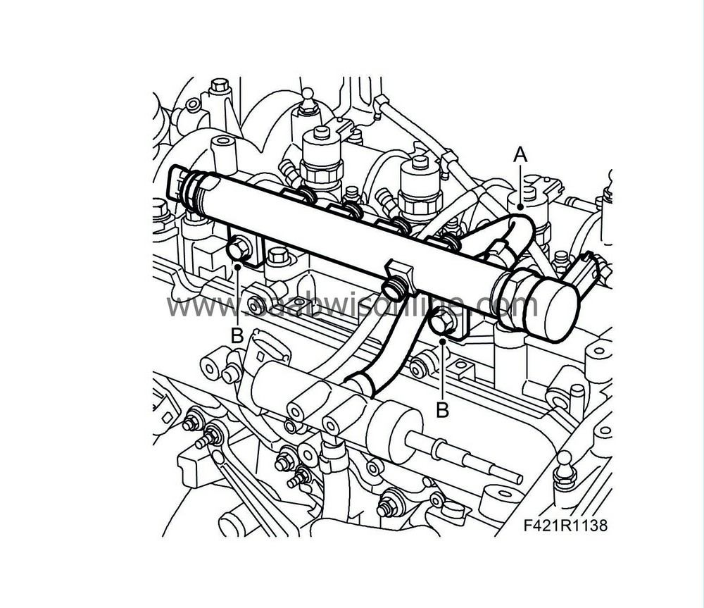
58.
|
Remove the fuel rail:
|
|
|
-
|
Remove the high-pressure hose, fuel rail - high-pressure pump (D)
|
|
|
-
|
Remove the high-pressure hoses to the injectors (C)
|
|
|
-
|
Remove the return hose (A)
|
|
|
-
|
Remove the screws that hold the fuel rail (B)
|
|
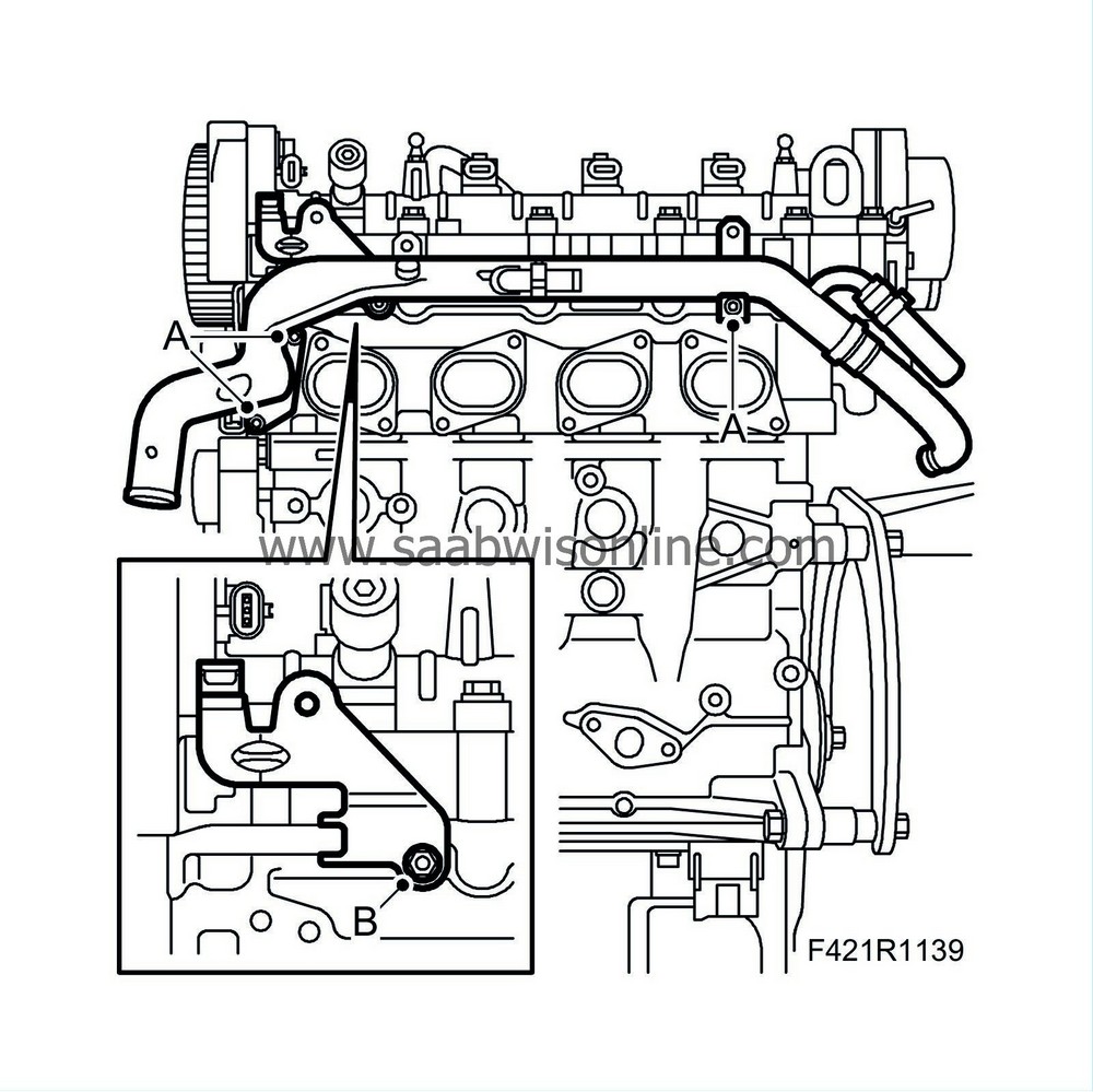
59.
|
Remove the coolant pipe (A).
|
|
60.
|
Remove the timing belt cover's holder (B).
|
Important
|
|
If the injectors are to be refitted, mark the injectors so that they can be refitted to the same cylinder.
|
|
|
|
|
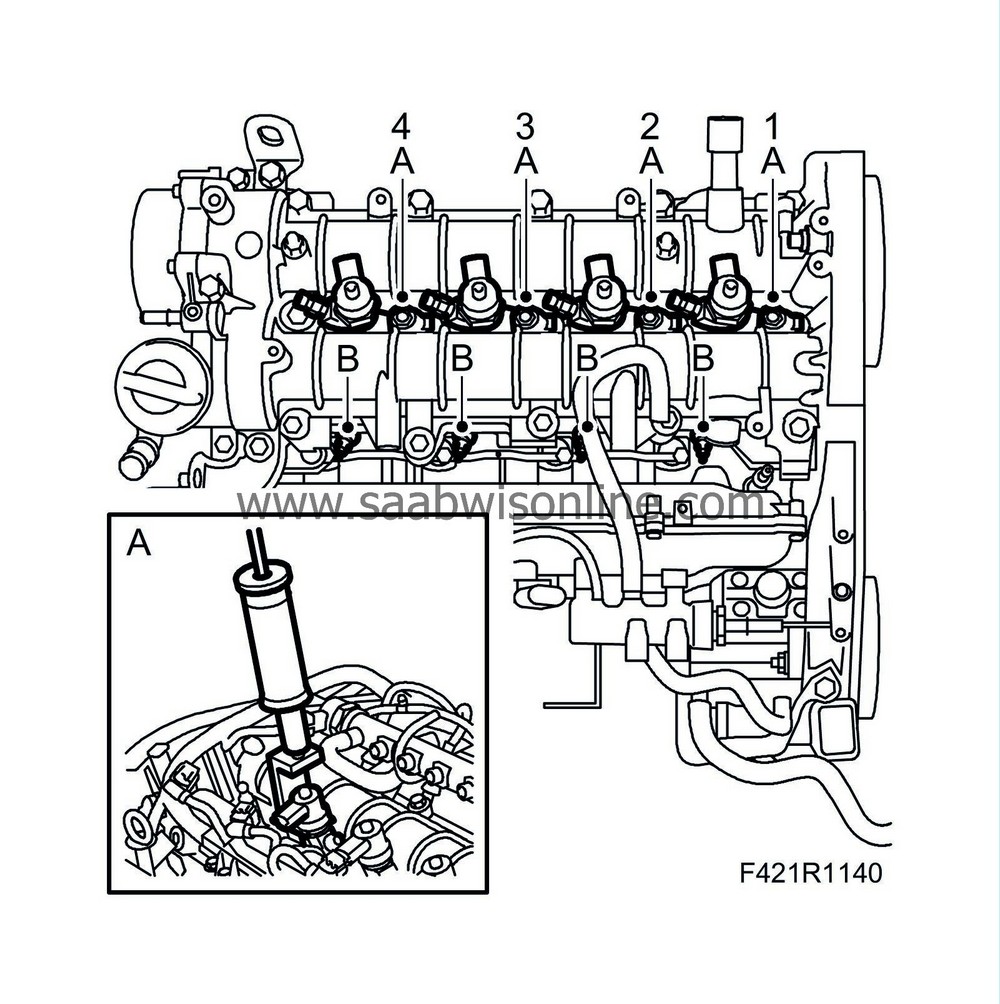
61.
|
Remove the injectors:
|
Note
|
|
If the nozzles cannot be raised by hand, use 32 025 013 Injector removal tool with 83 90 270 Sliding hammer and 32 025 012 Sliding hammer adapter.
|
|
|
|
-
|
Remove the injectors in the following order, 1-2-3-4. Illustration
|
|
|
-
|
Remove the nut for the injector (A) holder.
|
|
|
-
|
Lift up the injector (A) (small illustration)
|
|
62.
|
Remove the glow plug (B).
|
|
63.
|
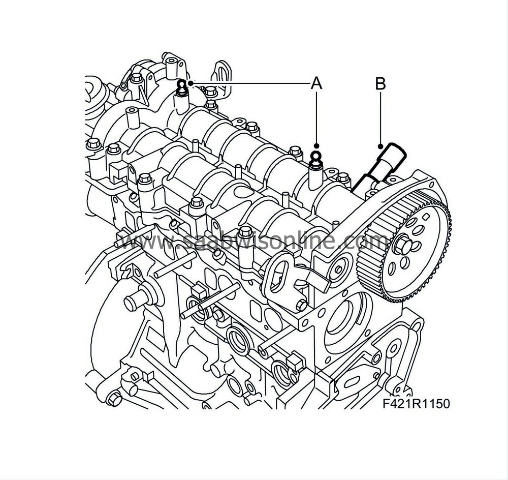
Undo the nut on the high-pressure pump gear:
|
|
|
-
|
Counterhold with tools KM-6347 and KM-956-1.
|
|
64.
|
Remove the high-pressure pump gear:
|
|
|
-
|
Pull away the high-pressure pump's drive wheel (A)
|
|
|
-
|
Counterhold with an open spanner
|
|
65.
|
Certain cars
: Remove the bracket (A).
|
|
66.
|
Remove the high-pressure pump:
|
|
|
-
|
Remove the high-pressure pump's return hose (A)
|
|
|
-
|
Remove the high-pressure pump (B)
|
|
67.
|
Remove the high-pressure pump's bracket (A).
|
|
68.
|
Remove the intake manifold with throttle valve module and EGR valve (A).
|
|
69.
|
Remove the noise absorbing panel on the oil sump (A).
|
|
70.
|
Remove the bracket to the exhaust pipe on the lower section of the rear edge of the oil sump (B).
|
|
71.
|
Remove the coolant pump (A).
|
|
72.
|
Remove the tension pulley (B).
|
|
73.
|
Remove the idler wheel (C).
|
|
75.
|
Remove the engine cover bracket (A).
|
|
78.
|
Detach the engine from the engine stand.
|
|
79.
|
Position the engine on a suitable surface.
|
|
80.
|
Detach the engine lift from the engine and remove the lifting eyes from the engine.
|


