Camshaft cover, front, B284
|
|
Camshaft cover, front, B284
|
|
1.
|
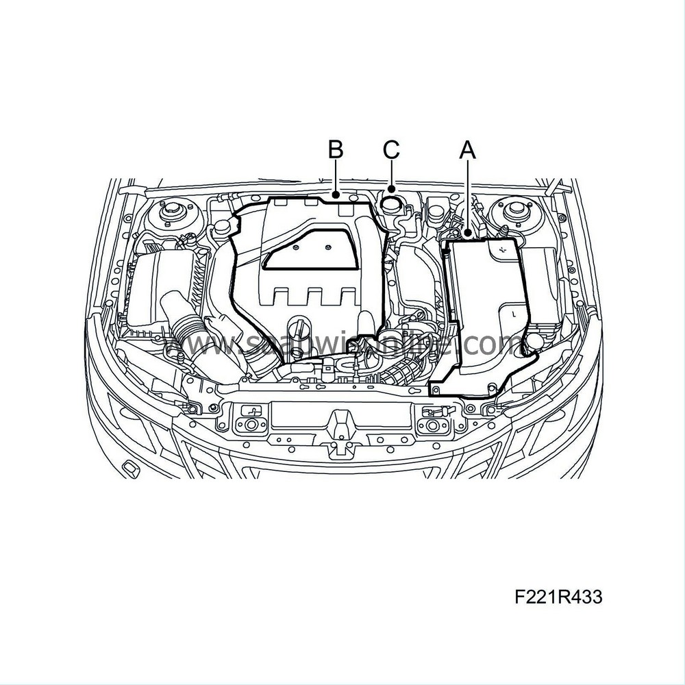
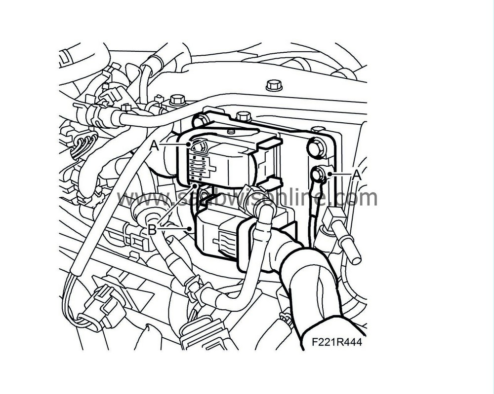
Remove the battery cover (A), the coolant pipe and the negative cable.
|
|
2.
|
Remove the upper engine cover (B).
 Warning
|
|
The cooling system is under pressure. Hot coolant and steam can escape.
|
|
- Open the cap slowly to release the pressure.
|
|
- Carelessness can cause eye and burn injuries
|
|
|
|
|
|
|
|
3.
|
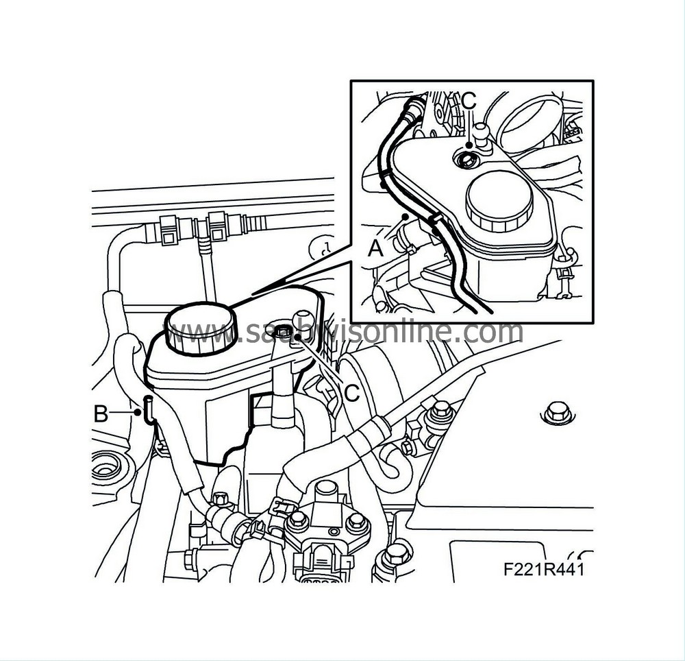
Open the expansion tank cap (C) and relieve any excess pressure.
|
Important
|
|
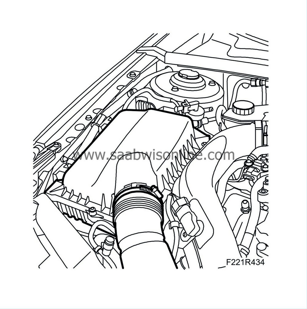
When removing the air cleaner casing cover, be careful not to damage the brake vacuum pump sensor.
|
|
|
|
|
4.
|
Remove the upper section of the air cleaner,
|
Important
|
|
Take care when releasing the locking mechanism on the connector so as not to damage the connector. Pull the connector straight out when unplugging avoid bending the pins. For further information regarding connectors, refer to Connectors, handling and inspection.
|
|
|
|
|
5.
|
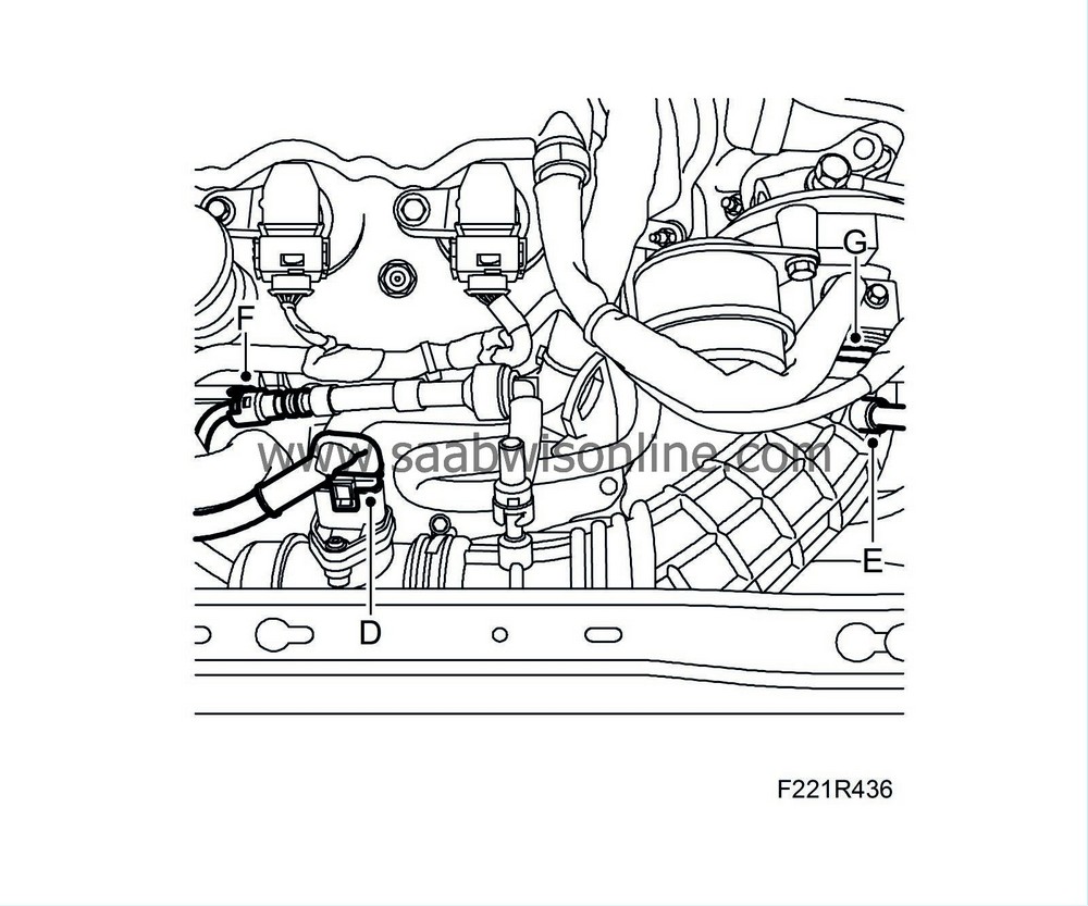
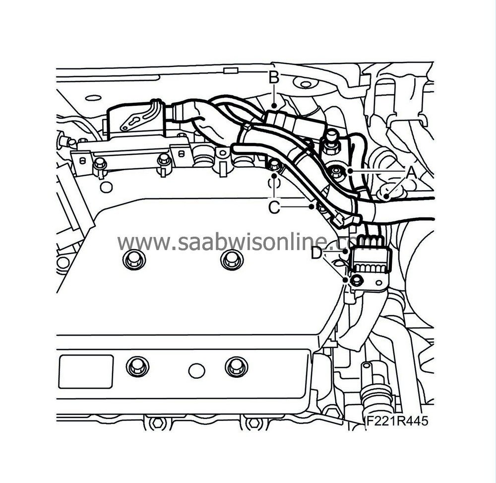
Remove the secondary air pipe (A), the hose clip (B), the wiring harness from the clip (C) and remove the intake manifold (D) between the air filter and the mass air flow sensor.

|
|
6.
|
Unplug the mass air flow sensor connector (D), and remove the hose (E) from the turbocharger's intake manifold and the crankcase ventilation line (F).
|
|
7.
|
Undo the hose clip (G) and remove the intake hose and the mass air flow sensor from the turbocharger.
|
|
8.
|
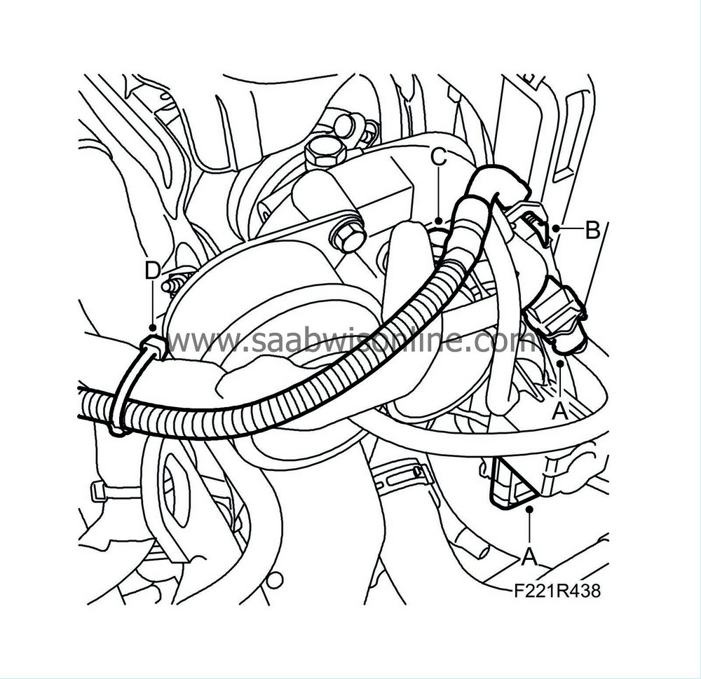
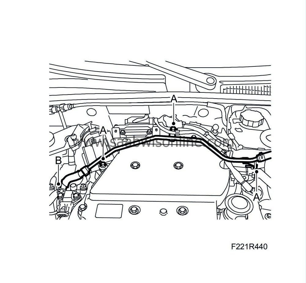
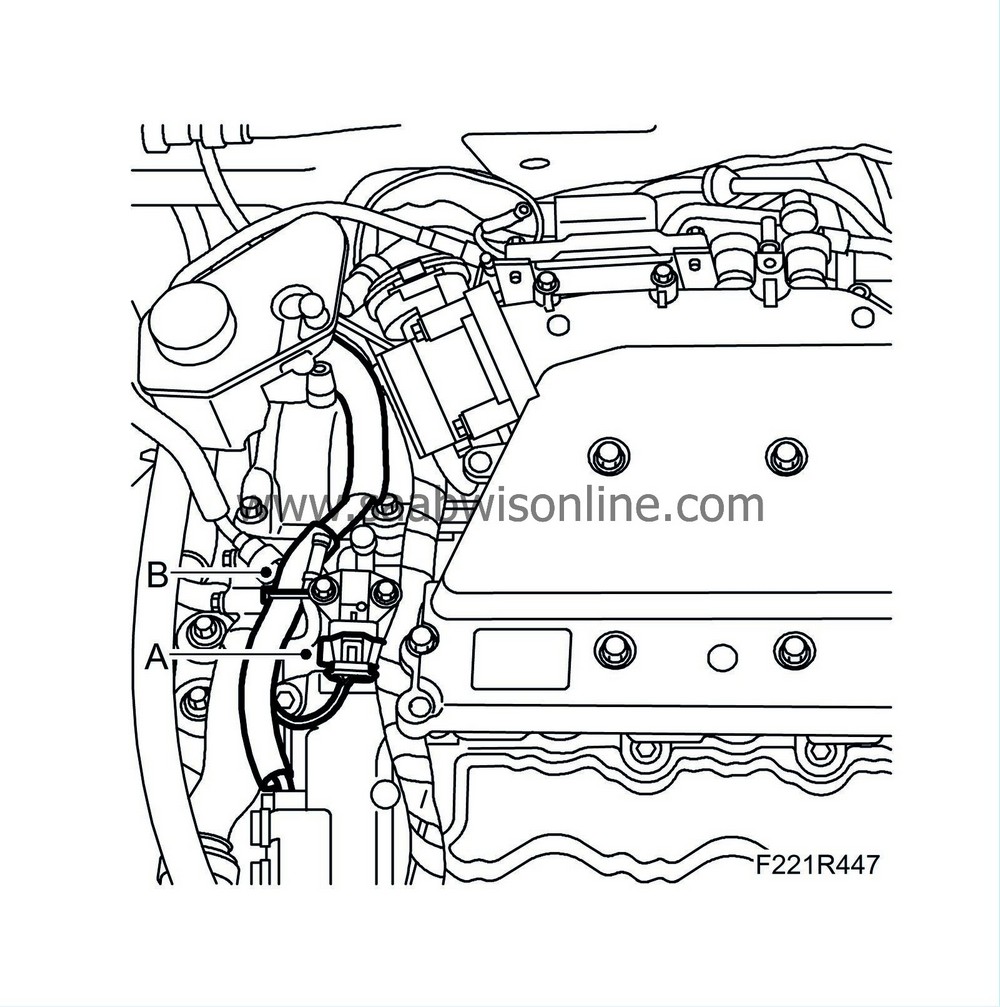
Remove the charge air pipe by first removing the clips (A) and then unplug the boost pressure sensor connector (B). Remove the power steering line from the clips (C).

|
|
10.
|
Remove the electrical connections (A) and the cable clip (B) from the turbocharger.
|
|
11.
|
Remove the crankcase ventilation hose (C) from the turbocharger.
|
|
12.
|
Cut off the cable tie (D) and fold the wiring harness and the crankcase ventilation hose aside
|
|
13.
|
Remove both of the secondary air injection pump's pipes (B) and unplug the connector.
|
|
14.
|
Remove the front lifting eye (A).
|
|
15.
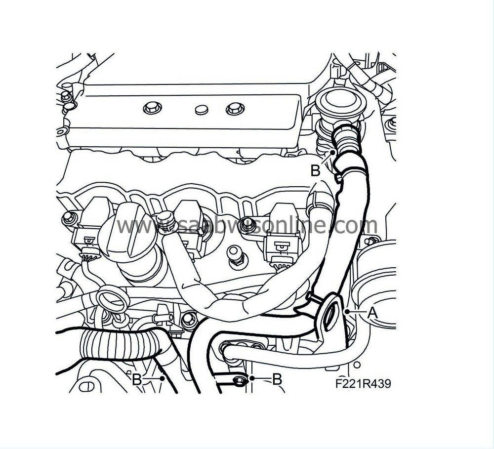
|
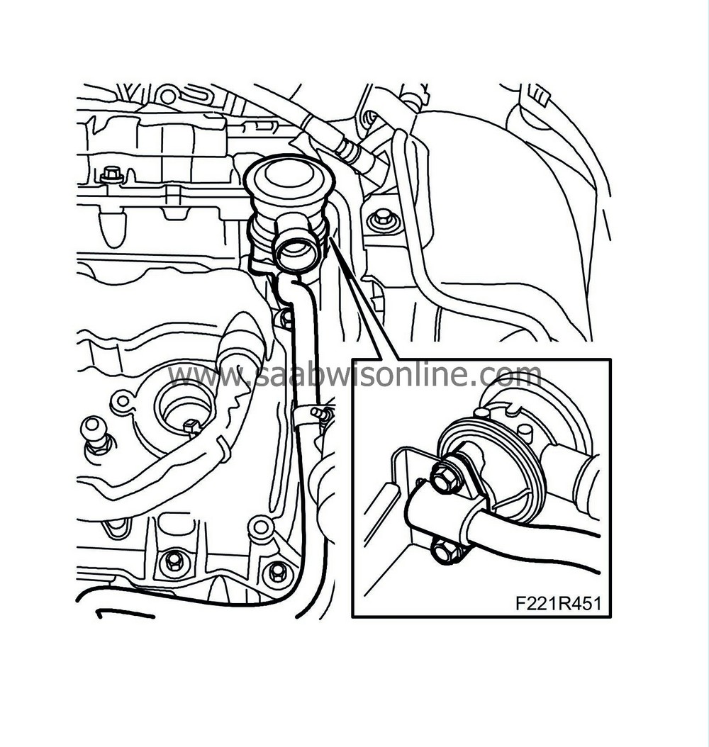
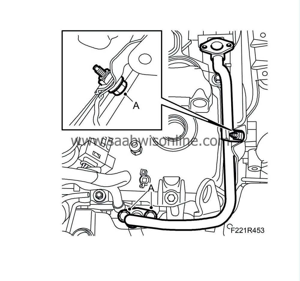
Remove the bolts (A) and remove the breather pipe (B) from the coolant port. Plug the pipe and fold the line aside.
|
|
16.
|
Detach the vacuum hose (A) and the fuel hose (B) from the power steering fluid reservoir and remove the bolt (C).
|
|
17.
|
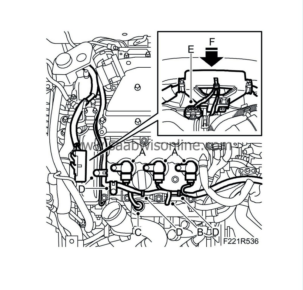
Remove the ignition coils (A) for cylinders 2, 4 and 6.

|
|
18.
|
Remove the left-hand grounding point. (B)
|
|
19.
|
Lift up the heat shield and unplug the coolant temperature sensor connector. (C)
|
|
20.
|
Detach the wiring harness (D) from the camshaft cover.
|
|
21.
|
Unplug the connectors (E) from the camshaft position sensor and from the camshaft solenoid valve.
|
|
22.
|
Release the hook and lift up the wiring harness holder slightly (F).
|
|
23.
|
Release the right-hand ground cable from the wiring harness. Carefully cut the tape.
|
|
24.
|
Remove the engine control module's ground cables (A).
|
|
25.
|
Unplug the engine control module connectors (B) (608A and 608B)
|
|
26.
|
Remove the cable duct (A) from the intake manifold.
|
|
27.
|
Unplug the connectors for the atmospheric pressure sensors (B).
|
|
28.
|
Detach the corner bracket and move it aside. (C)
|
|
29.
|
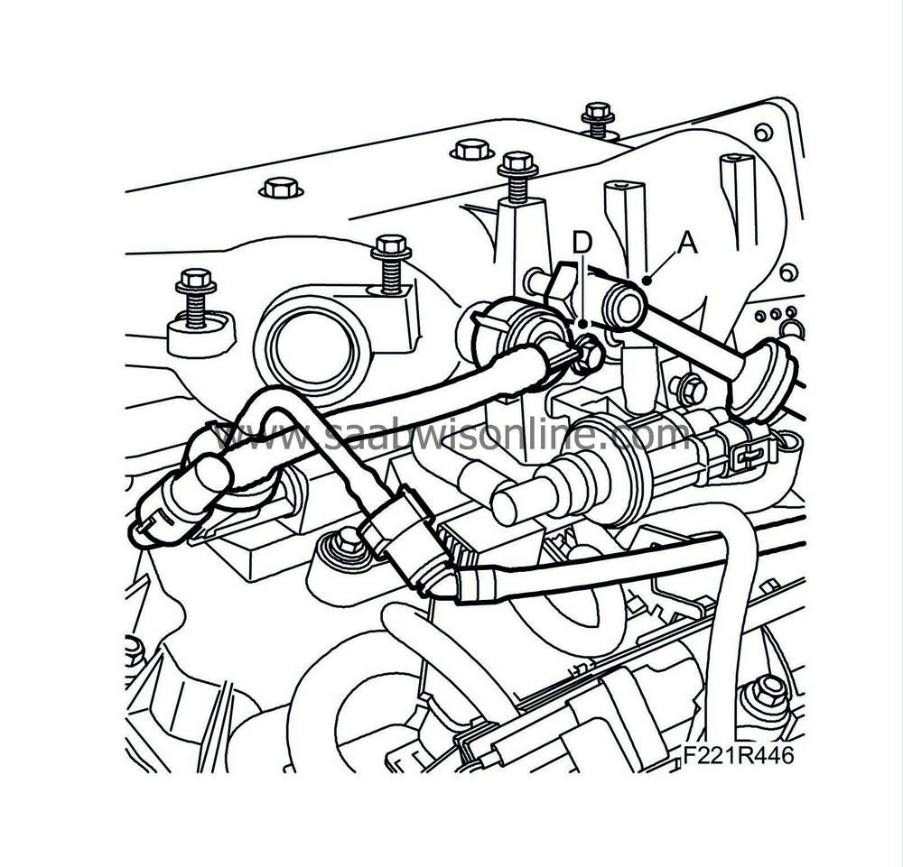
Remove the bolt holding the injectors' bracket and unplug the connector (D).
|
|
30.
|
Remove the brake vacuum hose (A) from the intake manifold.
|
|
31.
|
Remove the crankcase ventilation (D) from the intake manifold.
|
|
32.
|
Unplug the fuel pressure sensor connector (A).
|
Warning
|
|
The work involved in removing the fuel pipe requires working with the vehicle's fuel system. The following points should therefore be heeded in conjunction with these measures:
|
|
• Have a class BE fire extinguisher on hand! Be aware of the risk of sparks, i.e. in connection with electric circuits, short-circuiting, etc.
|
|
• Absolutely No Smoking!
|
|
• Ensure good ventilation! If there is approved ventilation for evacuating fuel fumes then this must be used.
|
|
• Wear protective gloves! Prolonged exposure of the hands to fuel can cause irritation to the skin.
|
|
• Wear protective goggles.
|
|
|
|
|
|
|
|
33.
|
Remove the fuel line (B), use 83 95 261 Fuel line tool. Collect any spilled fuel with a rag.
|
|
34.
|
Remove the upper intake manifold bolts (A).

|
|
35.
|
Lift up the upper intake manifold and unplug the throttle body connector (B). Lift away the intake manifold
|
|
36.
|
Remove the gasket and cover the inlet ducts.
|
|
37.
|
Remove the fuel rail with injectors and wiring harness (A). The injector for cylinder 1 may need to be removed from the fuel rail.
|
|
38.
|
Remove the lower part of the intake manifold (A). Seal the inlet ducts to the cylinder head using lint-free rags.
|
|
39.
|
Remove the secondary air system's valve (A) for cylinders 2-4-6.
|
|
40.
|
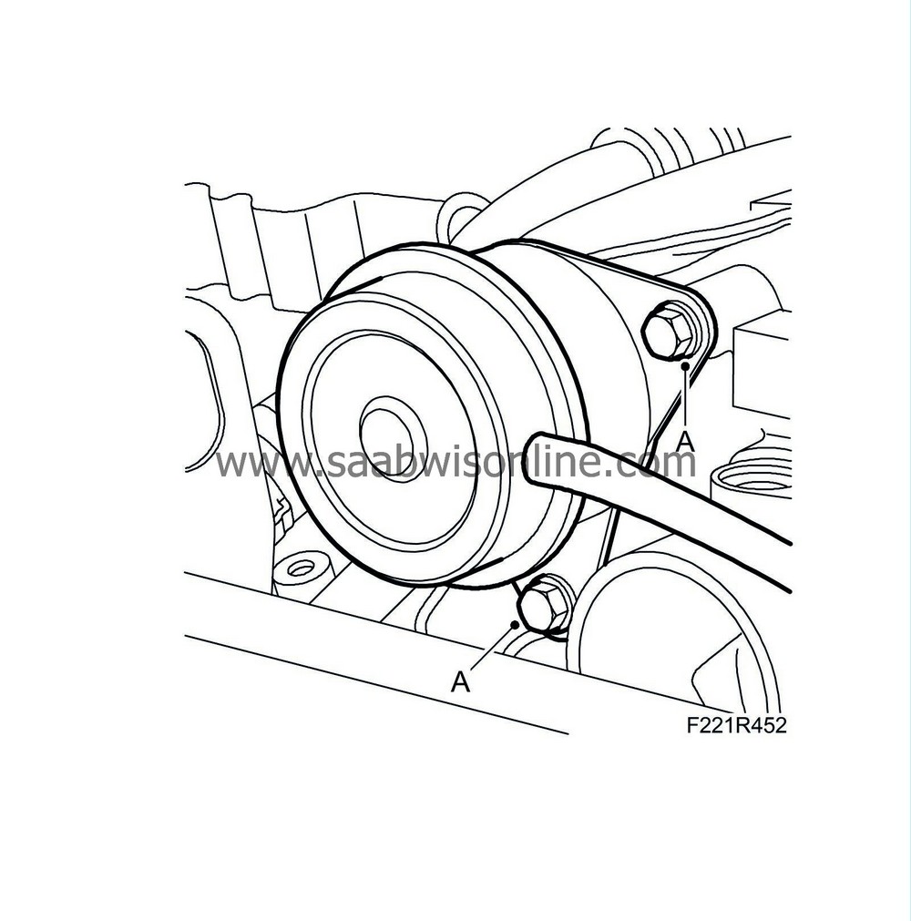
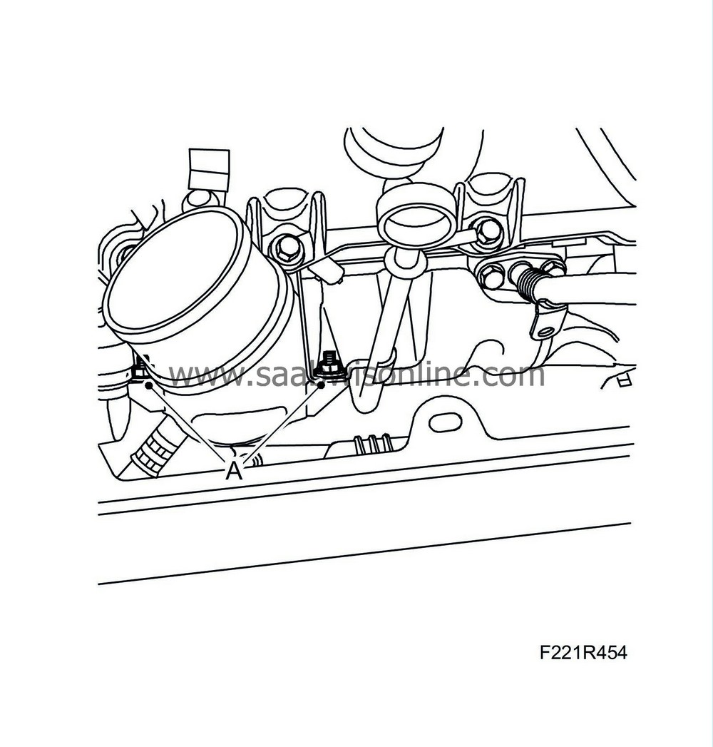
Detach the turbocharger diaphragm unit by removing the bolts (A) so that the unit can be moved slightly to the side.
|
|
41.
|
Remove the secondary air pipe (A).
|
|
42.
|
Remove the upper bolts (A) for the turbocharger delivery pipe.
|
|
43.
|
Remove the camshaft cover bolts and rubber bushings.
|
|
44.
|
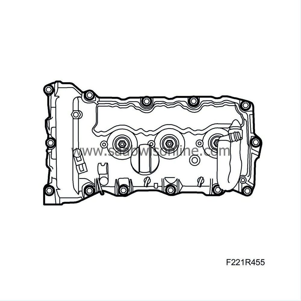
Remove the camshaft cover for cylinders 2-4-6.
|
|
45.
|
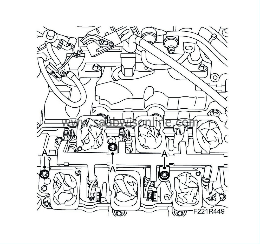
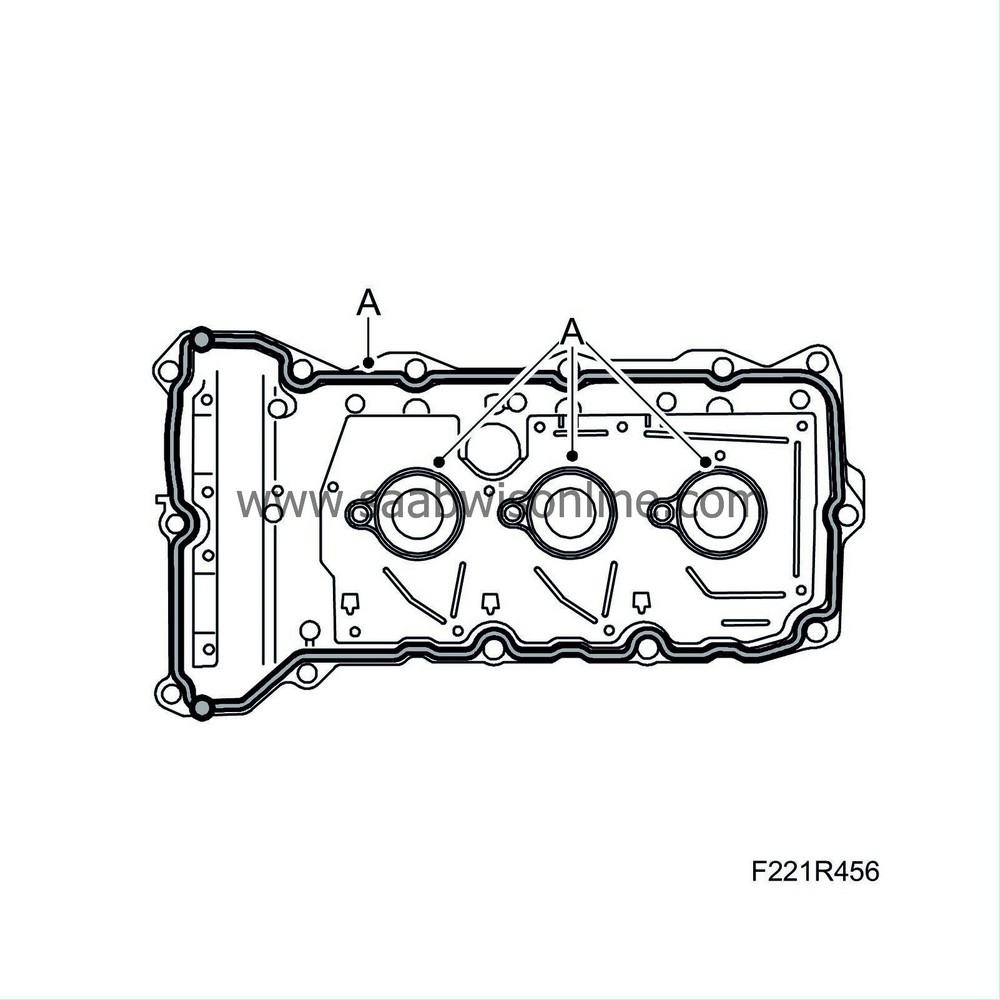
Remove the camshaft cover gasket and seals around the spark plug holes (A).
|
|
1.
|
Clean the sealing surfaces of the camshaft cover.
|
|
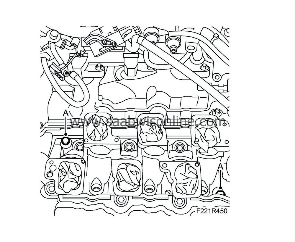
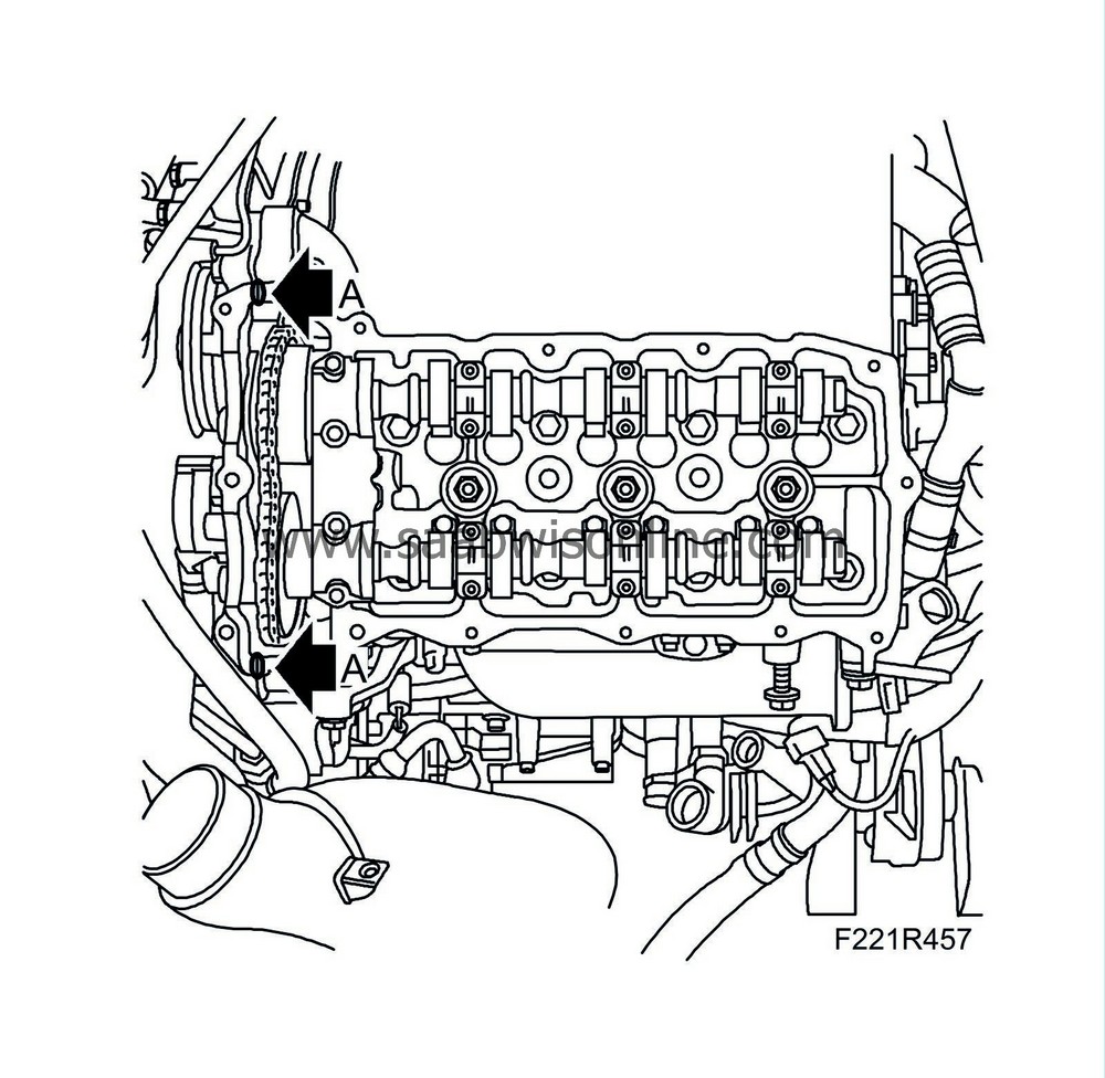
3.
|
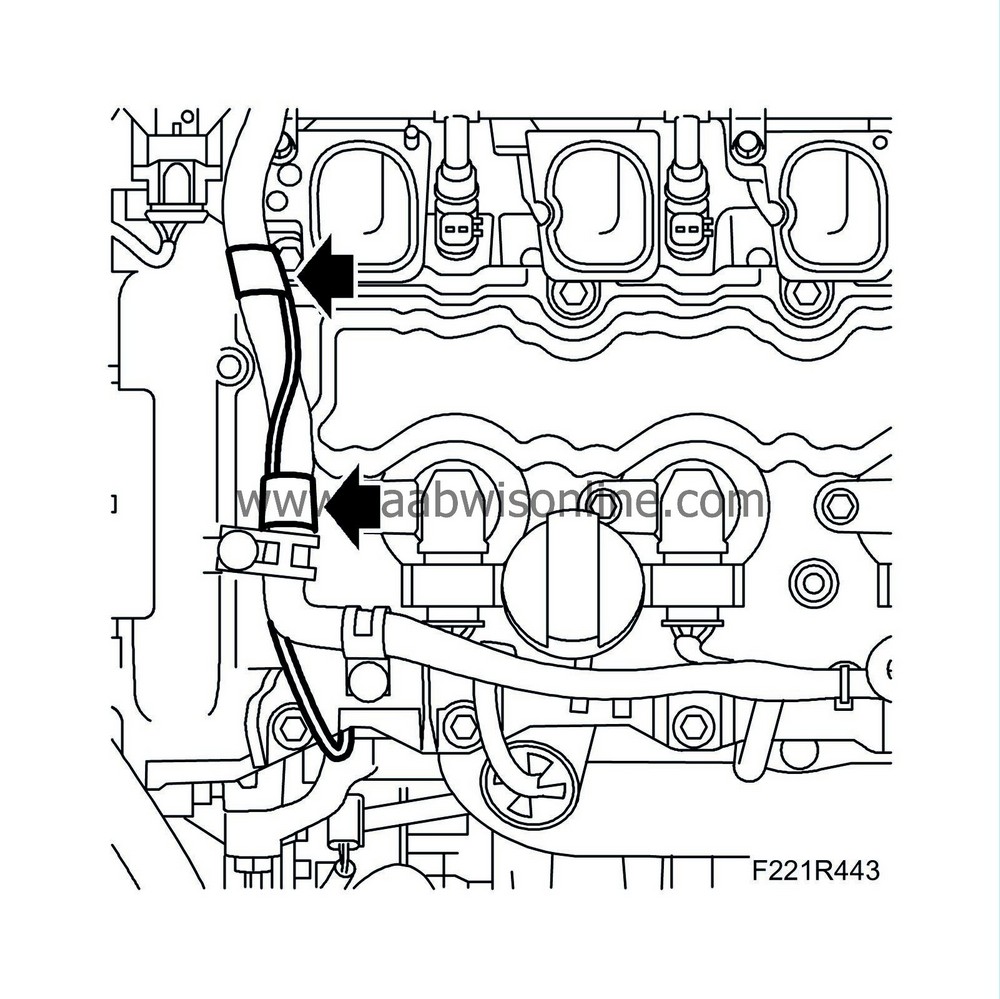
Add a dot of 93 160 951 Flange sealant on each mating face between the cylinder head and the timing cover as illustrated (A).
|
|
4.
|
Position the camshaft cover.
|
|
5.
|
Fit the bolts with new rubber bushings.
Tightening torque 10 Nm (8 lbf ft)
|
|
6.
|
Fit the upper bolts to the turbocharger delivery pipe (A).
|
|
7.
|
Fit the secondary air pipe (A). Use a new seal.
Tightening torque, bolts: 10 Nm (8 lbf ft)
Tightening torque to exhaust manifold: 22 Nm (16 lbf ft)
|
|
8.
|
Fit the secondary air system's check valve. Use a new seal.
|
|
9.
|
Fit the turbocharger's diaphragm unit by fitting the bolts (A).
|
|
10.
|
Clean the sealing surfaces and fit the lower section of the intake manifold (A) with a new seal. Remove the rags from the inlet ducts.
Tightening torque, bolts: 23 Nm (17 lbf ft)
|
|
11.
|
Fit the fuel rail with injectors and wiring harness (A).
Tightening torque, bolts: 10 Nm (8 lbf ft)
|
|
12.
|
Clean the sealing surfaces and fit the intake manifold upper section in place with new seals and plug in the throttle body connector (B).
|
|
13.
|
Fit the intake manifold bolts (A).
Tightening torque 23 Nm (17 lbf ft)
|
|
14.
|
Fit the fuel line (B).
|
Important
|
|
Take care when plugging in the connector so as not to damage or press out the pins/sleeves in the connector. For further information regarding connectors, refer to Connectors, handling and inspection.
|
|
|
|
|
15.
|
Plug in the fuel pressure sensor connector (A).
|
|
16.
|
Fit the crankcase ventilation to the intake manifold (D).
Tightening torque, bolt: 10 Nm (8 lbf ft)
|
|
17.
|
Fit the brake vacuum hose to the intake manifold (A).
|
|
18.
|
Plug in the injector connectors and fit the bracket (D).
Tightening torque, bolt: 10 Nm (8 lbf ft)
|
|
19.
|
Reposition the corner bracket and fit the bolts (C).
|
|
20.
|
Plug in the atmospheric pressure sensor connector (B).
|
|
21.
|
Fit the cable duct to the intake manifold (A).
|
|
22.
|
Plug in the engine control module connectors (B) (608A and 608B).
|
|
23.
|
Fit the engine control module's ground cables (A), one on each side.
|
|
24.
|
Secure the ground cable to the wiring harness.
|
|
25.
|
Plug in the connectors for the camshaft position sensor and for the camshaft solenoid valve (E) and fit the holder (F) for the camshaft cover.
|
|
26.
|
Attach the wiring harness (D) to the camshaft cover using new cable ties.
|
|
27.
|
Plug in the coolant temperature sensor connector (C) and press down the heat shield.
|
|
28.
|
Install the ignition coils for cylinders 2-4-6. Plug in the connectors (A).
Tightening torque, bolts: 10 Nm (8 lbf ft)
|
|
29.
|
Fit the left-hand grounding point (B).
|
|
30.
|
Fit the power steering fluid reservoir's bolt (C).
Tightening torque 10 Nm (7 lbf ft)
|
|
31.
|
Fit the vacuum hose (A) and the fuel hose (B) to the power steering fluid reservoir.
|
|
33.
|
Plug in the connector and fit both of the secondary air injection pump's pipes (B).
|
|
34.
|
Fit the engine's lifting eye.
Tightening torque, bolt: 65 Nm (48 lbf ft)
|
|
35.
|
Attach the crankcase ventilation line (C) to the turbocharger.
Tightening torque, bolt: 10 Nm (8 lbf ft)
|
|
36.
|
Fit the turbocharger wiring harness. Plug in the connectors (A) and fit the cable clip (B). Fit the cable tie (D).
|
|
37.
|
Fit the coolant return line (B). Fit the clip and the bolts (A).
Tightening torque, bolts: 10 Nm (8 lbf ft)
|
|
38.
|
Fit the charge air pipe. Fit the clips (A).
Tightening torque, clip: 3.5 Nm (2.5 lbf ft)
Plug in the boost pressure sensor connector (B). Secure the power steering line (C) in the clips.
|
|
39.
|
Fit the intake hose and the mass air flow sensor to the turbocharger.
Tightening torque, clip (G) 3.5 Nm (2.5 lbf ft)
|
|
40.
|
Plug in the mass air flow sensor connector (D) and fit the hose (E) for the turbocharger intake manifold and fit the crankcase ventilation line (F) to the dipstick tube.
|
|
41.
|
Fit the turbocharger intake manifold (D) between the air filter and the mass air flow sensor, and the secondary air pipe (A) and wiring harness to the clip (C).
Tightening torque, clip (B) 3.5 Nm (2.5 lbf ft)
Tightening torque, bolt (D) 1.5 Nm (1.1 lbf ft)
|
|
42.
|
Fit the top section of the air filter.
|
|
43.
|
Replace the upper engine cover (B).
|
|
44.
|
Connect the negative cable and fit the coolant pipe and the battery cover (A).
Tightening torque, clips 3.5 Nm (2.5 lbf ft)
|
|
45.
|
Check the coolant level.
|
|
46.
|
Carry out Procedures after disconnecting the battery.
|


