Alternator, B284, 4WD, (RHD)
|
|
Alternator, B284, 4WD, (RHD)
|
|
1.
|
Remove the battery cover and disconnect the negative battery cable.
|
|
3.
|
Remove the front right wheel.
|
|
4.
|
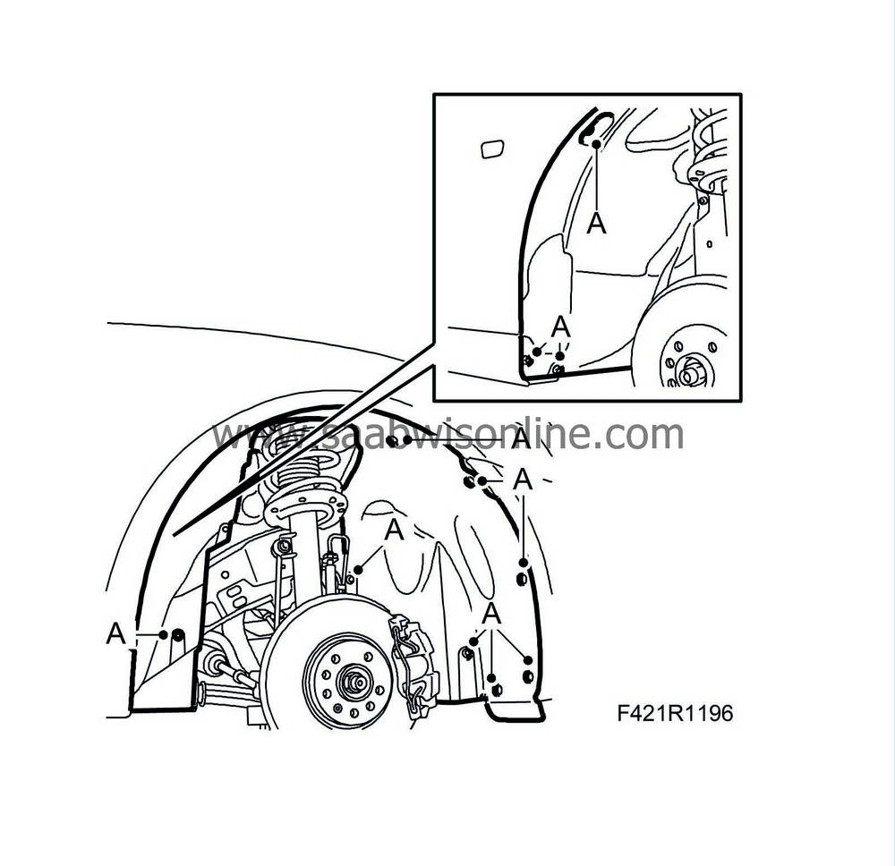
Remove the right-hand wing liner (A).
|
|
5.
|
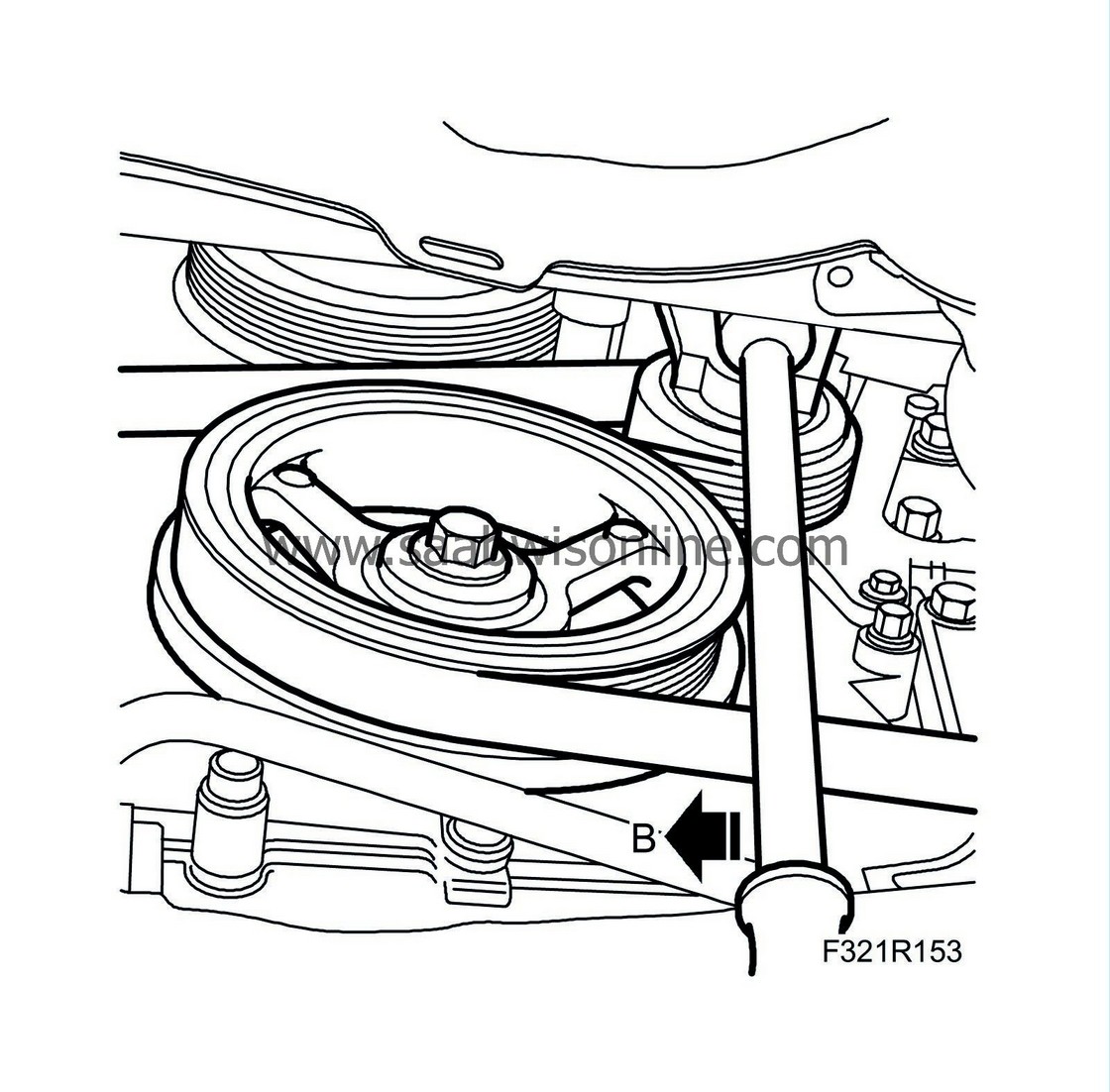
Relieve the belt tensioner and unhook the belt. Use a 1/2" drawbar handle (B)
|
|
6.
|
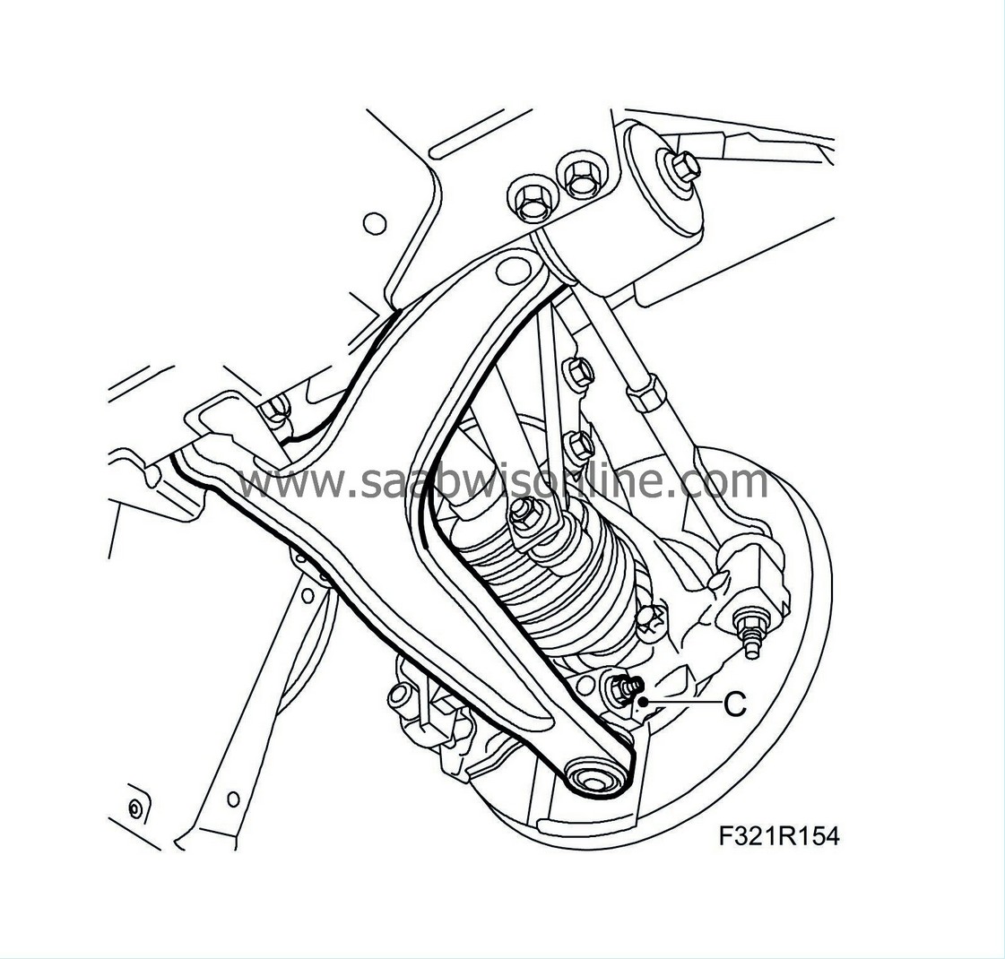
Remove the bolt (C) from the steering swivel member, lower the suspension arm and place a
83 95 238 Wedge
between the suspension arm and the anti-roll bar.
 Warning
|
|
Use protective goggles to protect against flying splinters of metal.
|
|
|
|
|
|
|
|
7.
|
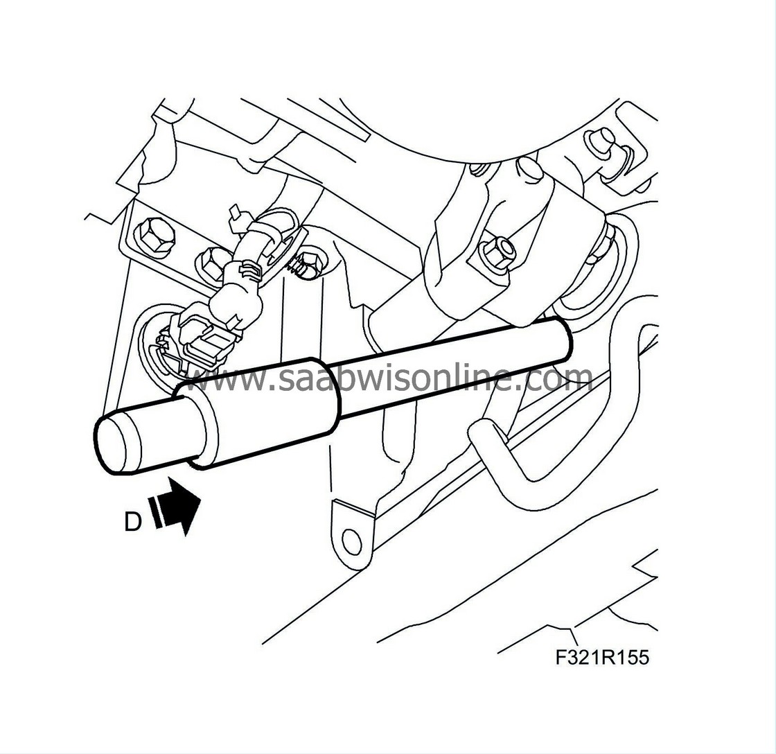
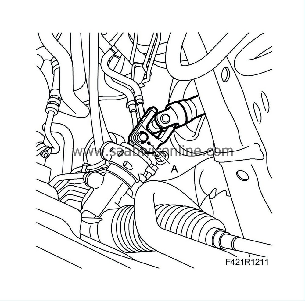
Tap the drive shaft out of the intermediate shaft with a brass drift and large hammer. (D) Move aside the drive shaft.
|
|
8.
|
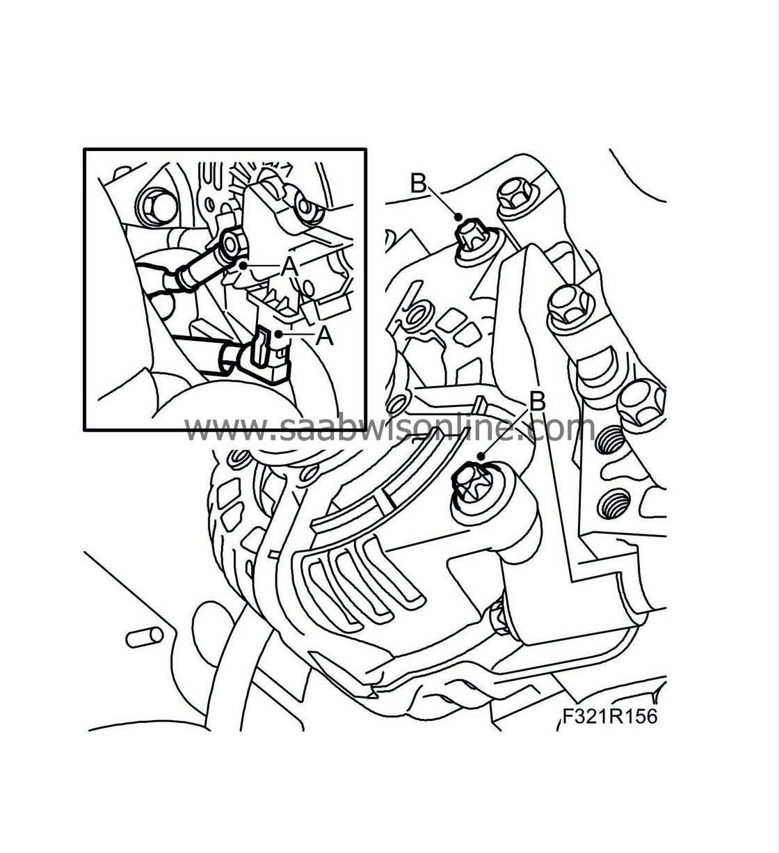
Remove the alternator electrical connections (A).
|
|
9.
|
Remove the alternator fixing bolts (B). If necessary, prise engine to left slightly.
|
|
10.
|
Remove the steering axle.
|
|
11.
|
Remove the wedge. Remove the right anti-roll bar link (A) from the anti-roll bar. Hold with an open 17 mm thin wrench.
|
|
13.
|
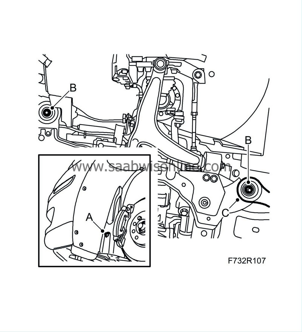
Remove the front part (A) of the wing liner and bend out slightly.
|
|
14.
|
Remove the subframe bolts (B) on both sides. Remove the stays (A) from the body.
|
|
15.
|
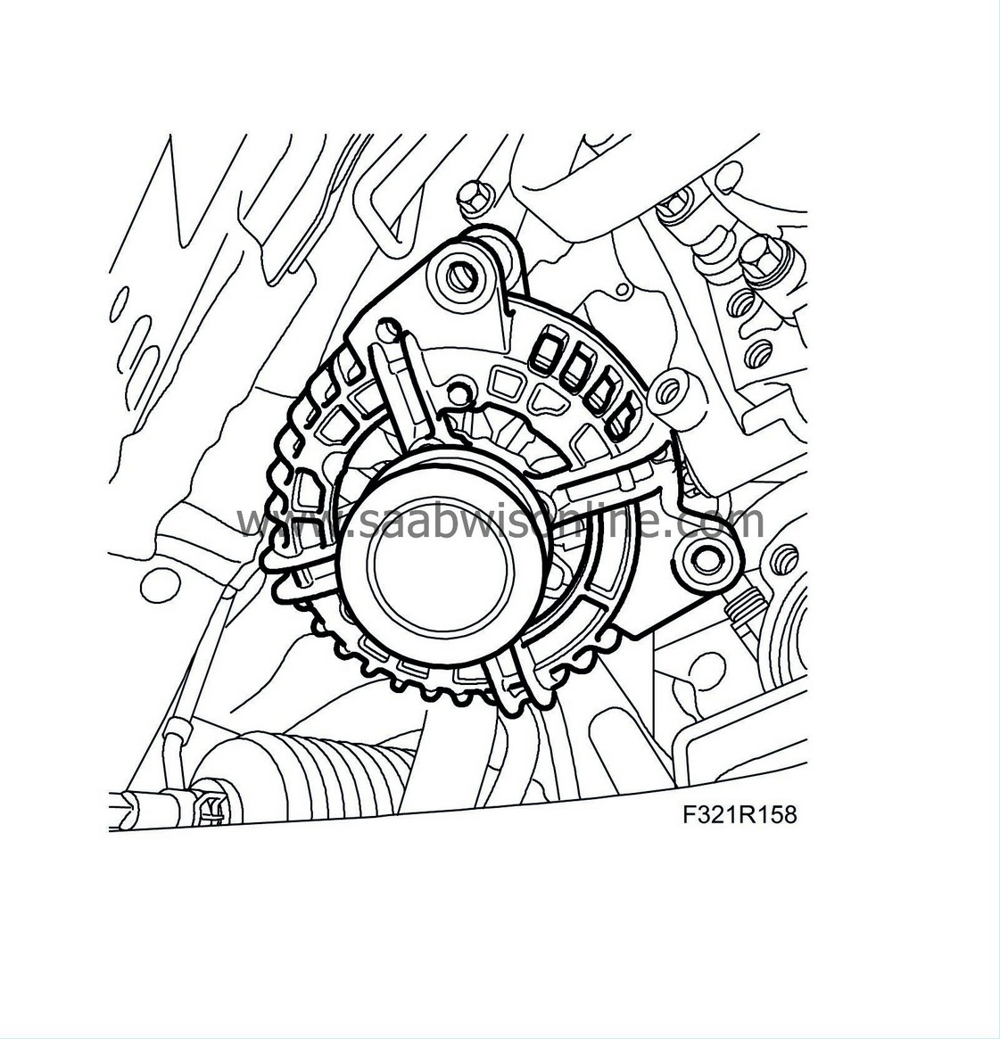
Guide out alternator, see diagram.
|
|
1.
|
Guide in alternator, see diagram.
|
|
3.
|
Fit the front subframe bolts (B) on both sides.
Tightening torque 75 Nm +135° (55 lbf ft +135°)
|
|
4.
|
Fit the stays and the rear subframe bolts (B) on both sides. Enter the rear stay bolts (C) before tightening the subframe bolts.
Tightening torque 75 Nm +135° (55 lbf ft +135°)
|
|
5.
|
Lower and pull away the trolley lift.
|
|
6.
|
Tighten the rear stay bolts (C).
Tightening torque 90 Nm +45° (66 lbf ft +45°)
|
|
7.
|
Fit the front wing liner (A).
|
|
8.
|
Install the steering axle.
|
|
9.
|
Fit the right anti-roll bar link (A) from the anti-roll bar. Hold with an open 17 mm thin wrench.
|
|
10.
|
Fit the alternator (B). If necessary, prise the engine to the left slightly. If the top alternator bolt cannot be inserted, grind away 4 mm of the bolt guide pin.
Tightening torque 24 Nm (18 lbf ft)
|
|
11.
|
Install the alternator electrical connections (A).
|
|
13.
|
Fit the drive shaft to the intermediate shaft. Make sure the lock ring clicks into place.
|
|
14.
|
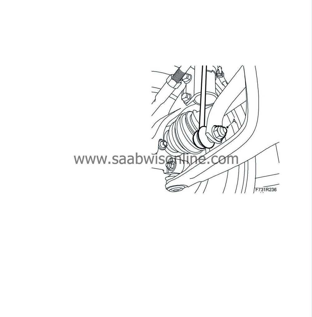
Connect the ball joint to the steering swivel member with a nut and bolt (C). The pin must be visible above the steering swivel member before the bolt is fitted. Tighten the nut.
Tightening torque 50 Nm (37 lbf ft)
|
Warning
|
|
Press up the pin carefully.
|
|
The groove in the pin must be visible in the screw hole in the spindle housing.
|
|
If the rubber gaiter is pressed down, it will not seal properly to the swivel pin.
|
|
|
|
|
|
|
|
15.
|
Relieve the belt tensioner, use a 1/2" drawbar handle (B) and mount the belt.
|
|
16.
|
Install the right-hand wing liner (A).
|
|
19.
|
Connect the negative cable of the battery.
|
|
20.
|
Fit the battery cover.
|
|
21.
|
When changing, check battery, see
Battery check
and charge battery if necessary, see "Charging the battery".
|


