PRE-RELEASE
Gearbox, removal and fitting
| Gearbox, removal and fitting |
| To remove |
| 1. |
Place covers on the wings to protect the paintwork from damage and dirt and remove the upper engine cover.

|
|
| 2. |
Remove the battery cover.
|
|
| 3. |
Disconnect the battery terminals and remove the battery.
|
|
| 4. |
Undo the cable clamp under the battery tray.
|
|
| 5. |
Unplug the bonnet switch connector.
|
|
| 6. |
Remove the battery tray.

|
|
| 7. |
Undo the ground cable from the engine mounting
|
|
| 8. |
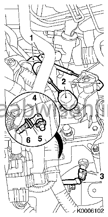
Undo the delivery line from the gearbox
Seal off the brake fluid reservoir with 30 07 739 Hose pinch-off pliers . Pull free the locking clip (5) and pull out the delivery line (6) from the central clutch connector plug (4) Slightly squeeze together the locking clip put it in the connector plug |
|
| 9. |
Remove the clutch cables from the gearbox
Bend the gear selector cables (2) free from the gear change lever with KM-6042 2x Free from the support Note: Retract the sleeve (1) and pull out the cable from the support |
|
| 10. |
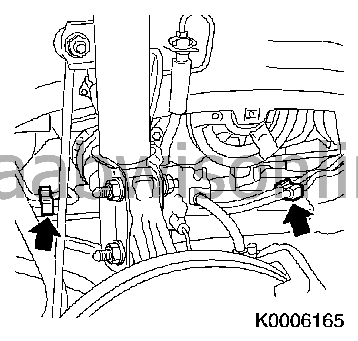
Free the gearbox at the top
3x Undo the upper bolts (arrowed) Note: Unscrew the rearward bolt first, so that the coolant hose can be lifted slightly 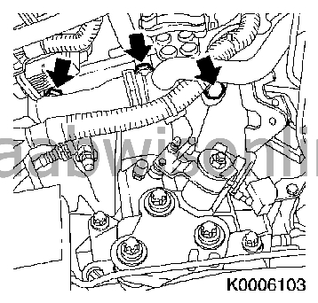
|
|
| 11. |
Remove the selector cable supports
2x Unscrew bolts (2) Remove the support (1) 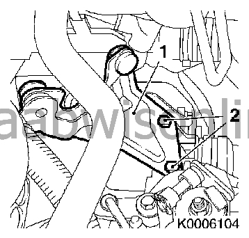
|
|
| 12. |
Fit
83 94 850 Lifting beam
(Follow the directions of manufacturer)
Support the radiator with two straps 83 95 212 Strap |
|
| 13. |
Remove the exhaust system
|
|
| 14. |
Put in place
83 96 145 Centring jig, subframe - engine
with
83 96 368 Supplementary set for centring jig
(1) in the front subframe
Note: In order to ensure that the drive train is correctly adjusted when the engine mount bolts, LH and RH, have been loosened, the drive train must be positioned relative to the front subframe with 83 96 145 Centring jig, subframe - engine Put in place 83 96 145 Centring jig, subframe - engine . The pins (3, 6) must be located in the guide holes in the front subframe 2x Tighten the adjustment rail bolts (arrowed) Screw up the rear support bearing (4) until it locates in the guide pin on the rear engine mount holder without any free-play Screw up the front support bearing (5) until it locates in the guide pin on the rear engine mount holder without any free-play 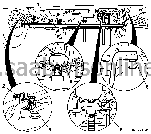
|
|
| 15. |
Remove the front subframe
Important 83 96 145 Centring jig, subframe - engine remains attached to the subframe and must not be adjusted |
|
| 16. |
Remove the LH engine mount
3x Unscrew bolts (1) Important: Check that the engine and engine components are not resting against the front suspension frame or subframe. Cables and hoses must not be stretched. |
|
| 17. |
Lower the engine/gearbox
Lower using lifting beam 83 94 850 Lifting beam , until the gearbox is not up against the subframe whilst removing 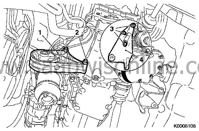
|
|
| 18. |
Remove the front engine mount (1)
2x Unscrew bolts (2) |
|
| 19. |
Remove the rear engine mount (4)
3x Unscrew the rear bolts (3) |
|
| 20. |
Remove the LH drive shaft
Note: Put an oil tray underneath as oil will run out Note: The drive shaft remains attached to the wheel hub Tie up the drive shaft to the underside of the car. Put in a plug |
|
| 21. |
Remove the RH drive shaft
Note: Put an oil tray underneath as oil will run out Note: The drive shaft remains attached to the wheel hub Tie up the drive shaft to the underside of the car. Put in a plug |
|
| 22. |
Detach the gearbox from the oil pan
3x Unscrew bolts (1) Important: Follow the directions of the manufacturer 87 92 608 Holder for single-column lift . 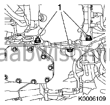
|
|
| 23. |
Fit the gearbox holder
87 92 608 Holder for single-column lift
(1)
Connect to the hydraulic lift and the gearbox 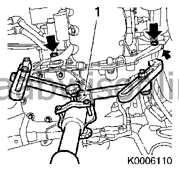
|
|
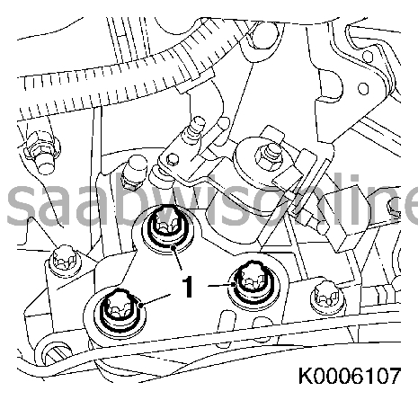
| 24. |
Detach the gearbox from the engine
3x Undo the bolts (arrowed) Free the gearbox from the engine Carefully lower the gearbox with 87 92 608 Holder for single-column lift - pay attention to wiring and other connections |
|
| 25. |
Fit the gearbox to the engine
Note: Smear a little lubricating grease on the drive shaft teeth before mounting the gearbox on the engine Important: Follow the manufacturer's directions carefully Carefully lift up the gearbox with the hydraulic lift Important: Check that no cables and holders are squeezed in between the engine and gearbox Adjust the gearbox and locate it evenly on the engine 3x Tighten the bolts (arrowed) (60 Nm)
|
|
| 26. |
Remove the gearbox holder
Remove the gearbox holder 87 92 608 Holder for single-column lift (1) from the hydraulic lift and the gearbox |
|
| 27. |
Fit the gearbox to the oil pan
3x Tighten the bolts (40 Nm)
|
|
| 28. |
Fit the LH engine mount on the gearbox
Note: Raise the engine/gearbox into position with 83 94 850 lifting beam . Check that there is some free play between the LH engine mount and the engine mount holder. 3x Screw the bolts into position but do not tighten as the engine/gearbox must be adjusted in relation to the front suspension frame.
|
|
| 29. |
Fit the gear selector cable support (1)
Fit to the support 3x Screw in the upper bolts on the gearbox but do not tighten yet. 2x Tighten the bolts (2) (20 Nm)
|
|
| 30. |
Fit the gearbox to the engine
3x Tighten the upper bolts (arrowed) (60 Nm) Note: Fit the longer bolt together with the coolant hose
|
|
| 31. |
Fit the RH drive shaft
Put an oil tray underneath as oil will run out Remove the plug |
|
| 32. |
Fit the LH drive shaft
Put an oil tray underneath as oil will run out Remove the plug
|
|
| 33. |
Fit the front engine mount on the gearbox
2x Tighten the bolts (80 Nm) |
|
| 34. |
Fit the rear engine mount holder to the gearbox
3x Tighten the bolts (80 Nm) |
|
| 35. |
Fit the subframe
Note: In order to ensure that the drive train is correctly adjusted when the engine mount bolts, LH and RH, have been loosened, the drive train must be positioned relative to the front subframe with 83 96 145 Centring jig, subframe - engine . see the service procedure "Front suspension beam, removing and fitting" Note: Check that the guide pins of the rear engine mount holder and the front engine mount are located in the support bearings (2, 3) on 83 96 145 Centring jig, subframe engine (1). The support bearing must not be adjusted. 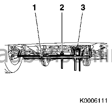
|
|
| 36. |
Remove
83 96 145 Centring jig, subframe - engine
Lower the engine/gearbox with 83 94 850 Lifting beam Note: The guide pin for the front engine mount and the rear engine mount holder must be located in the support bearing on 83 96 145 Centring jig, subframe - engine Remove the lifting beam |
|
| 37. |
Fit the LH engine mount
Tighten the three LH engine mount bolts (1) (55 Nm)
|
|
| 38. |
Fit the rear engine mount
Tighten the engine mount holder (80 Nm) |
|
| 39. |
Fit the front engine mount
Tighten the front suspension frame fixing using a new nut (80 Nm) |
|
| 40. |
Remove
83 96 145 Centring jig, subframe - engine
.
|
|
| 41. |
Fit the exhaust system
|
|
| 42. |
"Gearbox oil level, checking and adjusting"
see service procedure Gearbox oil level, checking and correcting F17 . 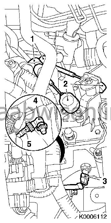
|
|
| 43. |
Assemble the gear selector cables to the gearbox
2x Fit into the support Note: Retract the sleeve (1) and fasten the cable into the support Attach the gear selector cables (2) to the gear cover |
|
| 44. |
Re-connect the reversing light switch to the wiring loom
Replace the wiring loom connector (3) |
|
| 45. |
Fit the delivery line (5)
Fit the central clutch delivery line connector plug (4) Caution: It must be securely snapped into place |
|
| 46. |
Hydraulic system, bleeding
see Bleeding the clutch hydraulic system . 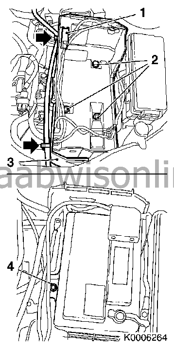
|
|
| 47. |
Attach the ground cable to the engine mounting.
Tightening torque 18 Nm (13 lbf ft) |
|
| 48. |
Fit the battery tray and the bonnet switch connector.
|
|
| 49. |
Fit the battery.
|
|
| 50. |
Fit the battery cover and upper engine cover.
|
|
| 51. |
Remove the wing covers.
|
|
| 52. |
Carry out
Measures after disconnecting the battery
.
|
|
