High-pressure pump, Z19DT
|
|
High-pressure pump, Z19DT
|
 Warning
|
|
The work involved in removing the fuel pump requires working with the vehicle's fuel system. The following points should therefore be heeded in conjunction with these measures:
|
|
•
|
Have a class BE fire extinguisher on hand! Be aware of the risk of sparks, i.e. in connection with electric circuits, short-circuiting, etc.
|
|
•
|
Absolutely No Smoking!
|
|
•
|
Ensure good ventilation! If there is approved ventilation for evacuating fuel fumes then this must be used.
|
|
•
|
Wear protective gloves! Prolonged exposure of the hands to fuel can cause irritation to the skin.
|
|
•
|
Wear protective goggles.
|
|
|
|
|
|
|
Warning
|
|
Diesel under high pressure! So wait for at least one minute after switching off the engine before starting work in the fuel system. Diesel fumes are explosive and can cause severe burn injuries.
|
|
|
|
|
|
|
Important
|
|
Be very thorough in terms of cleanliness when working in the fuel system. Malfunctions can also occur due to very small dirt particles. Prevent dirt from entering the fuel system by cleaning the hoses and plugging the pipes and lines upon removal using 93 161 370 Plug set. Store the components so that contaminants cannot enter.
|
|
|
|
1.
|
Open the bonnet and place a wing cover over the right wing.
|
|
2.
|
Remove the battery cover and the negative battery cable.
|
|
3.
|
Remove the upper engine cover.
|
|
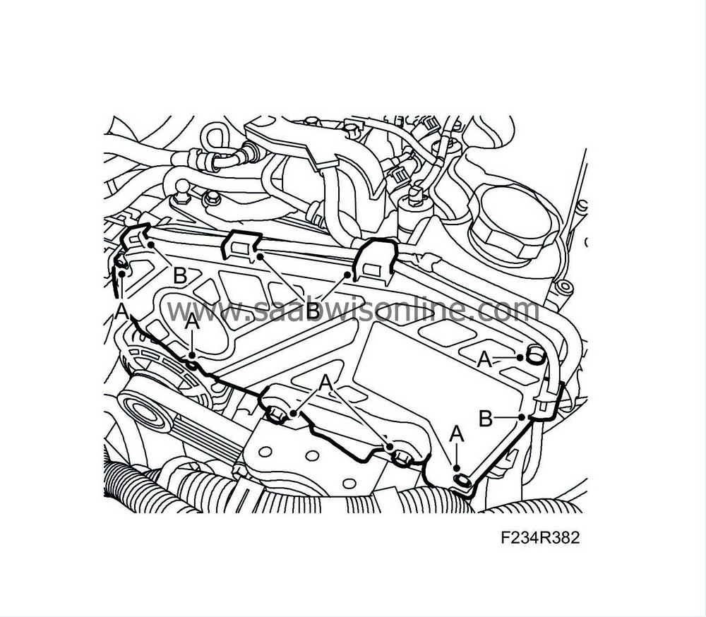
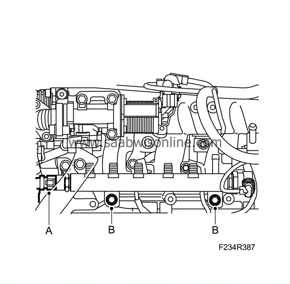
5.
|
Remove the bolts of the upper timing cover (A). Release the wiring harness from the clips (B) and remove the cover.
|
|
6.
|
Unplug and remove the camshaft position sensor connector (A).
|
|
7.
|
Remove the bracket and lifting eye (3 bolts).
|
|
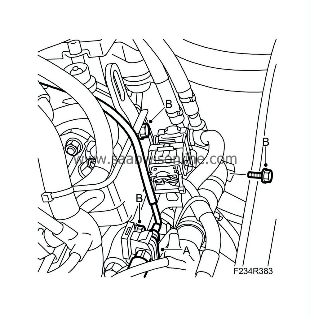
8.
|
Detach the return fuel line (A) from the return fuel tank using
83 95 261 Fuel line tool
. Have a cloth on hand to catch any spilled fuel.
|
|
9.
|
Remove the return fuel hose (B) form the pump.
|
|
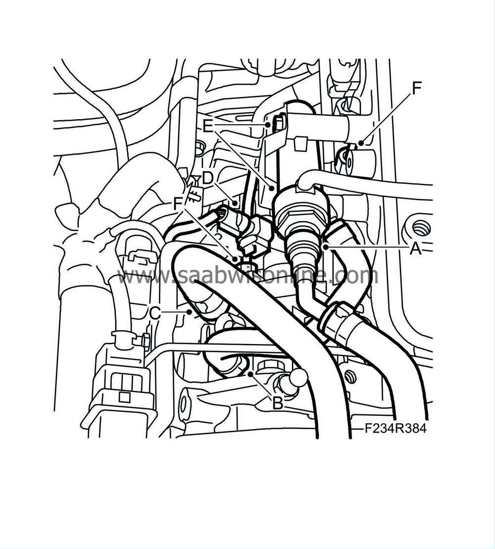
10.
|
Remove the fuel inlet hose (C) from the pump.
|
|
11.
|
Remove the fuel pressure sensor connector (D) from the pump.
|
|
12.
|
Remove the bolts (E) securing the return fuel collector.
|
|
13.
|
Detach the fuel pipe (F) from the pump and the fuel rail.
|
Important
|
|
Take care when releasing the locking mechanism on the connector so as not to damage the connector. Pull the halves straight apart to avoid bending the pins. For further information regarding connectors, refer to
Connectors, handling and inspection
.
|
|
|
|
|
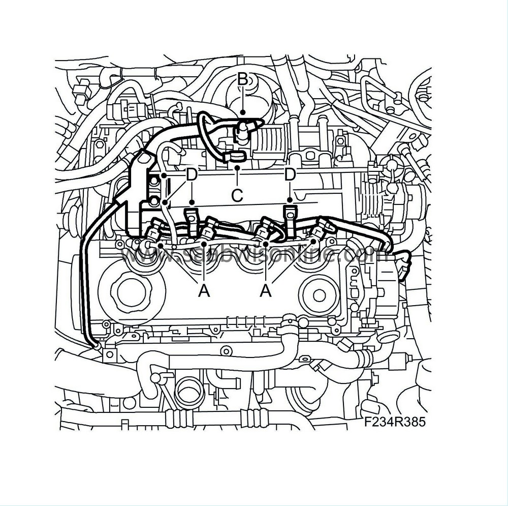
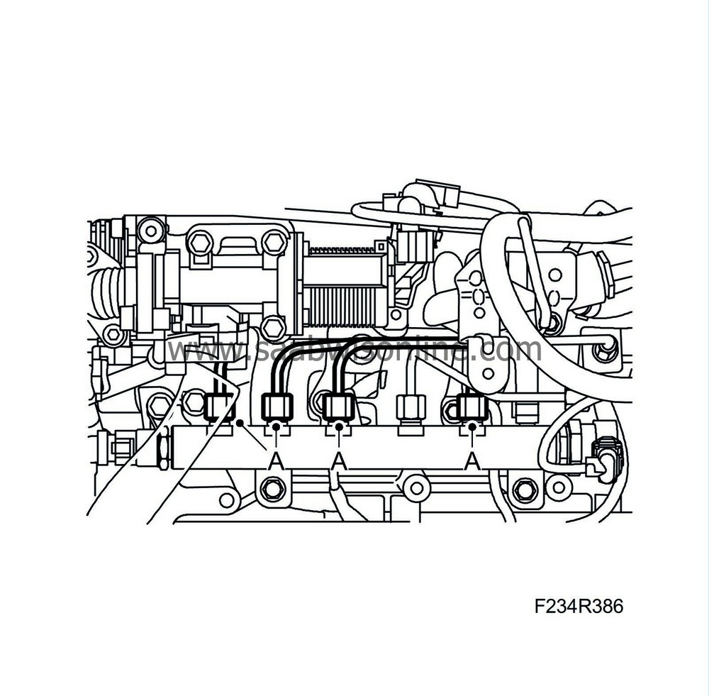
14.
|
Unplug the injector connectors (A) and EGR valve connector (B) and remove the intake manifold sensor (C).
|
|
15.
|
Detach the wiring harness (D) from the intake manifold.
|
|
16.
|
Detach the delivery lines (A) between the injectors and the fuel rail.
|
|
17.
|
Unplug the connector (A) that sits on the fuel rail.
|
|
18.
|
Detach the fuel rail (B) and put it aside.
|
|
19.
|
Remove the pulley nut:
|
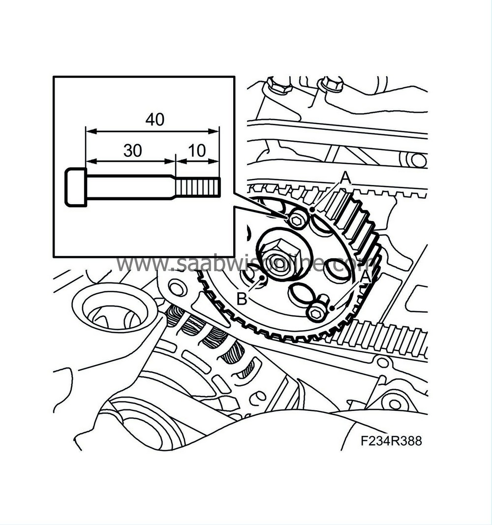
Important
|
|
When affixing the pulley, use two hex socket head screws M6 X 40 (30 mm unthreaded and 10 mm thread). The screws must be tightened the whole length of the thread. This way the pulley is prevented from moving out of position.
|
|
|
|
|
|
•
|
Turn the engine so it is possible to fit 2 Allen bolts (A) M6 x 40 (30 mm unthreaded and 10 mm threaded) through the holes in the pulley and to threads in the high-pressure pump bracket.
|
|
|
•
|
Remove the pulley nut (B). If necessary, hold with 32 025 019 Camshaft sprocket support and the handle from 83 95 360 Holding tool, crankshaft pulley.
|
|
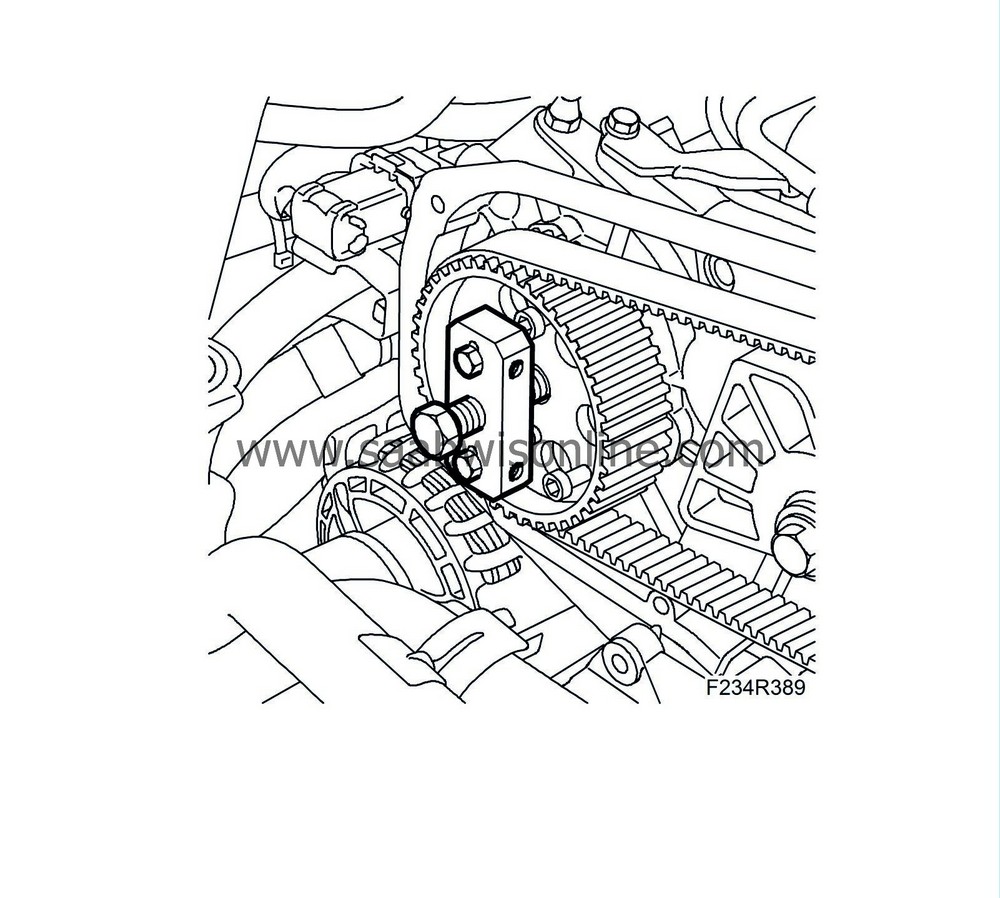
20.
|
Detach the high-pressure pump from the pulley by pressing the pump out with 32 025 005 Puller. Counterhold with a 30 mm wrench. Remove the puller.
|
|
21.
|
Remove the nuts (A) and washers using a magnet for the washers.
|
|
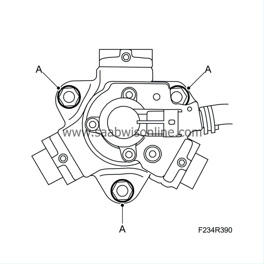
1.
|
Position the pump and fit washers and nuts (A).
Tightening torque 25 Nm (18 lbf ft).
|
|
2.
|
Fit the nut (B) to the high-pressure pump's pulley.
Tightening torque 50 Nm (36 lbf ft)
|
|
3.
|
Remove the bolts (A) holding the pulley in place.
|
|
4.
|
Attach the fuel rail (B).
|
Important
|
|
Take care when plugging in the connector so as not to damage or press out the pins/sleeves in the connector. For further information regarding connectors, refer to
Connectors, handling and inspection
.
|
|
|
|
|
5.
|
Plug in the fuel rail connector (A).
|
|
6.
|
Check that the fuel pipe sealing surfaces are clean and undamaged. Fit the pipes (A) without tension and mount the nuts by hand. Tighten the nuts of the fuel rail and the injectors.
Tightening torque 25 Nm (18 lbf ft)
|
|
7.
|
Fit the wiring harness (D) to the intake manifold.
|
|
8.
|
Plug in the injector connectors (A) and EGR valve connector (B) and fit the intake manifold sensor (C).
|
|
9.
|
Fit the fuel pipe (F) between the pump and the fuel rail. Mount the nuts by hand. If it is difficult to get the fuel pipe in place, unscrew the fuel rail retaining bolts slightly.
Tightening torque, fuel pipes 25 Nm (18 lbf ft)
Tightening torque, fuel rail 25 Nm (18 lbf ft).
|
|
10.
|
Fit the return fuel collector (E)
Tightening torque 9 Nm (7 lbf ft).
|
|
11.
|
Fit the fuel pressure sensor connector (D).
|
|
12.
|
Fit the fuel inlet hose (C) to the pump.
|
|
13.
|
Fit the fuel return hose (B) to the pump.
|
|
14.
|
Fit the return fuel line (A).
|
|
15.
|
Fit the bolts of the lifting eye and bracket (B).
|
|
16.
|
Plug in the camshaft position sensor connector (A).
|
|
17.
|
Fit the cover and bolts (A). Fit the wiring harness to the clips (B).
|
|
18.
|
Replace the upper engine cover.
|
|
20.
|
Connect the negative battery cable and fit the battery cover.
|
|
22.
|
Start the engine and turn it off.
|
|
23.
|
Remove the wing cover and close the bonnet.
|
|
24.
|
Connect the diagnostic tool and erase any diagnostic trouble codes.
|


