Valve cone, front cylinder head, B284 (new version)
|
|
Valve cone, front cylinder head, B284 (new version)
|
|
Important
|
|
Store all removed valve parts in the valve stand 83 93 787.
|
|
|
|
1.
|
Remove the
Camshaft cover, front, B284
 Warning
|
|
The cooling system is under pressure. Hot coolant and steam can escape.
|
|
- Open the cap slowly to release the pressure.
|
|
- Carelessness can cause eye and burn injuries
|
|
|
|
|
|
|
|
2.
|
Open the expansion tank cap and relieve any excess pressure.
|
|
4.
|
Undo the right-hand side of the spoiler shield.
|
|
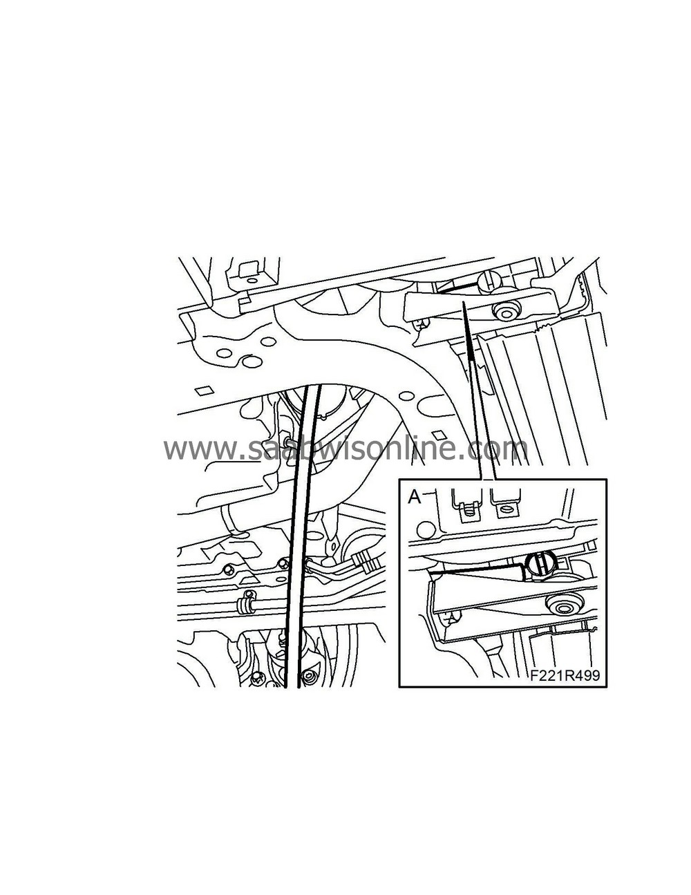
5.
|
Place a suitable receptacle under the radiator. Connect a hose (A) to the radiator and drain the coolant. Close the cock and refit the spoiler shield.
|
|
9.
|
Remove the spark plugs.
|
|
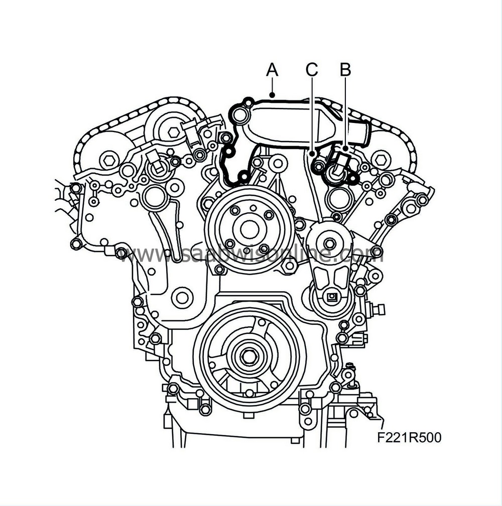
10.
|
Remove the coolant port (A).
|
|
11.
|
Remove the camshaft solenoid valve (695F) (B).
|
|
12.
|
Remove the camshaft position sensor (555F) (C).
|
|
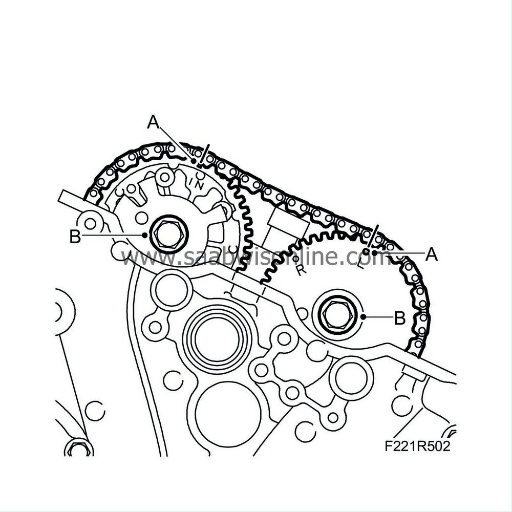
13.
|
Rotate the crankshaft so that the markings on the camshaft sprockets are visible, and the indentations align with the cylinder head. Use EN-48383-3 Adjustment tool (A) as a gauge (the camshafts are now in their neutral position).

|
|
16.
|
Lower the car.
|
Important
|
|
Store all removed valve parts in the valve stand 83 93 787.
|
|
|
|
|
17.
|
Mark the chain and camshaft sprockets so they can be refitted in the same position (A).
|
|
18.
|
Loosen the torque on the bolts (B) holding the camshaft sprockets. Counterhold using an open spanner on the camshaft flats (do not remove the bolts).
|
|
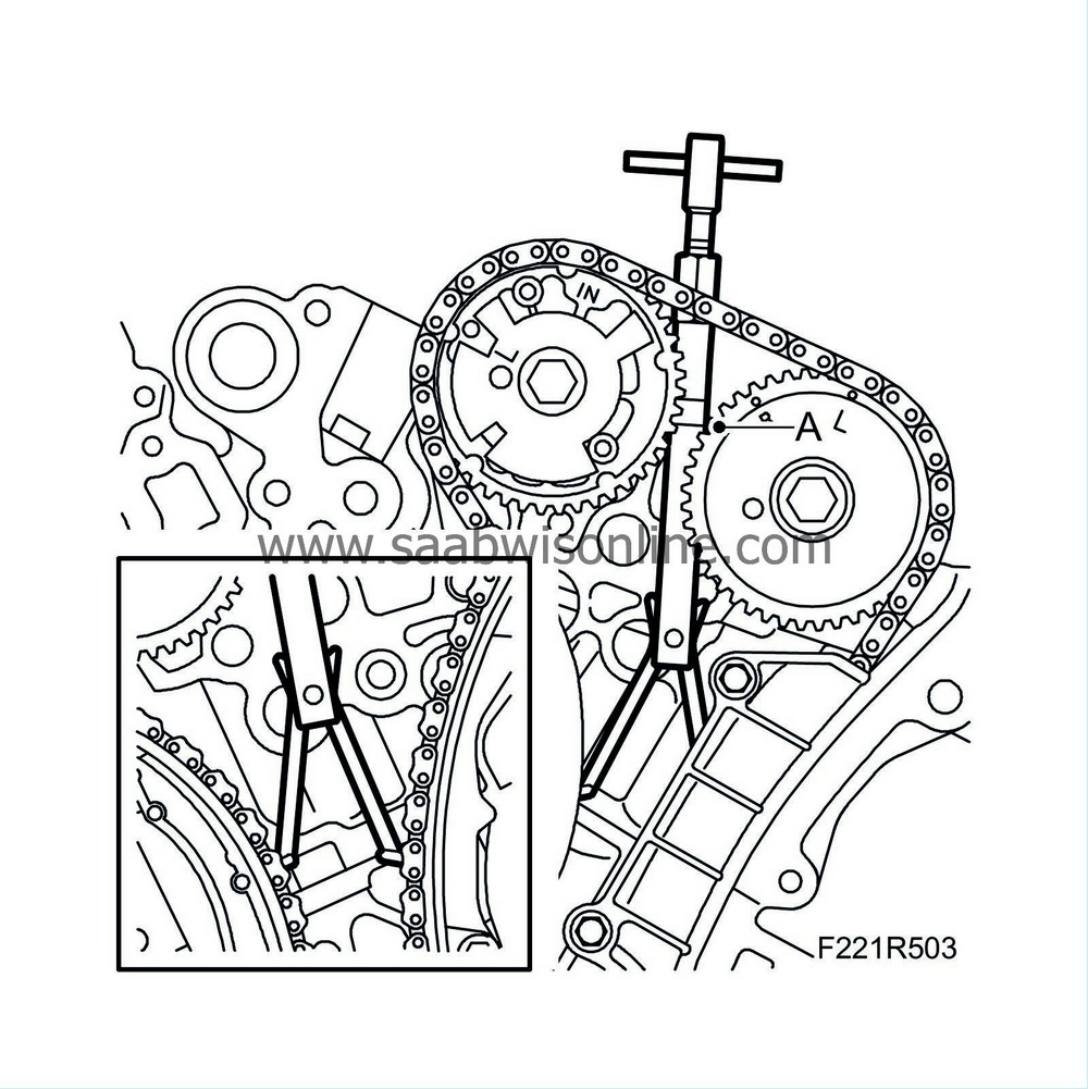
19.
|
Fit EN-48313 Fixing tool to the camshaft chain. Check that the tool grips the chain firmly, and that the lower groove of the tool (A) is level with the upper section of the cylinder head. (The timing cover is removed in the illustration for an improved view of how the tool should be fitted.)
|
|
20.
|
Tighten EN-48313 Fixing tool manually so that the chain is unloaded. Counterhold using an open spanner so that the tool does not turn.
|
Important
|
|
It is vital that EN-48313 is properly fitted. If tension is not relieved from the chain when the camshaft sprocket is removed, the chain tensioner will trigger automatically. To then adjust the chain tensioner, the timing cover must be removed.
|
|
|
|
|
21.
|
Remove the camshaft sprocket bolts.
|
|
22.
|
Remove the sprockets from the camshafts.
|
|
23.
|
Remove the camshaft bearing caps by loosening the bolts in stages - 1/2 to 1 turn. It is important that the removal ends at the bearing cap where the tappets are loaded. Note the markings on the bearing caps when refitting to ensure that they are in the correct locations (A).

|
|
24.
|
Lift out the camshafts and note the rear marking on the camshafts. (B) The last letters in the marking: LI = intake camshaft, front cylinder bank. LE = exhaust camshaft, front cylinder bank.
|
Important
|
|
Cover all return oil ducts in the cylinder head so that the valve cone or contaminants cannot fall down into the engine.
|
|
|
|
|
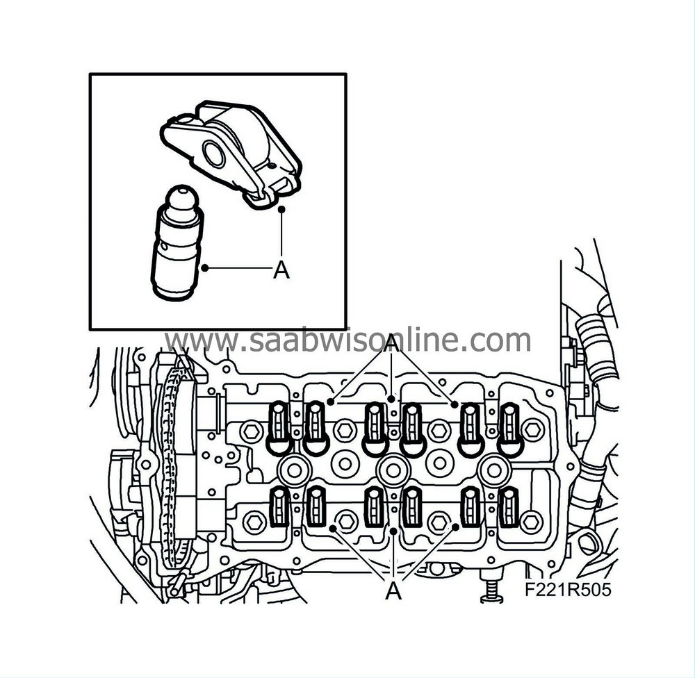
25.
|
Remove the roller rockers and the hydraulic adjuster elements (A). Store them in
83 93 787 Valve stand
so they do not get mixed up.
|
|
28.
|
Press down the valve plate with
EN-46110 Valve spring depressor
(B).
|
Important
|
|
The compressed air must not be disconnected when the valve cone is removed. Do not press on the valve stem either as counterpressure in the cylinder could reduce and the valve could fall down into the cylinder.
|
|
|
|
|
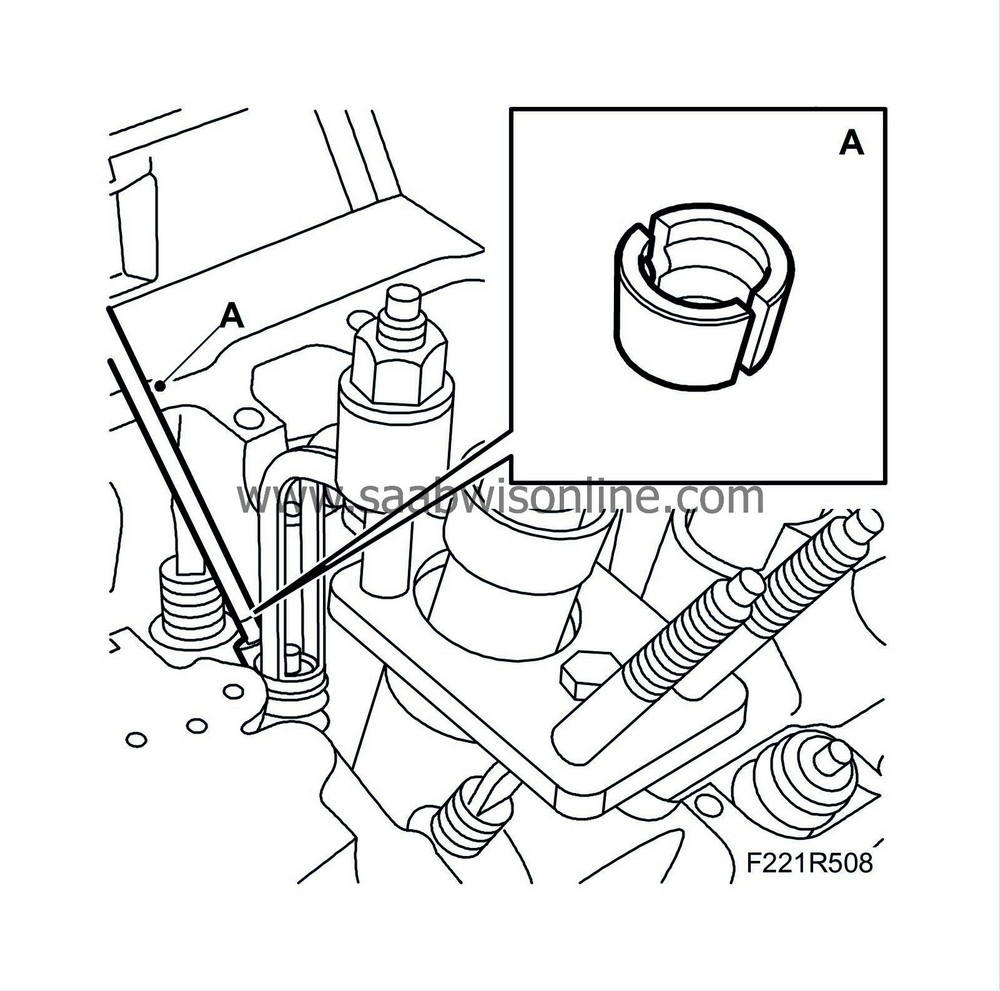
29.
|
Remove the valve cone with a magnet (A).
|
|
1.
|
Clean all parts and check contact surfaces and bearing surfaces for wear.
|
|
5.
|
Disconnect the compressed air and remove the air nipple.
|
|
6.
|
Position the camshafts and use EN-48383-3 Adjustment tool to check that the camshafts are mounted at the correct angle (B). The last letters in the marking: LI = intake camshaft, front cylinder bank. LE = exhaust camshaft, front cylinder bank.
|
|
7.
|
Fit the bearing caps as illustrated (markings on caps). Start where the cams point down and load the tappets. Note: Tighten the bolts in stages - 1/2 to 1 turn.
Tightening torque 10 Nm (7 lbf ft)
|
Important
|
|
Tighten the bolts in stages - 1/2 to 1 turn.
|
|
|
|
|
8.
|
Fit the sprockets with chain on the camshafts. Tighten the bolts by hand.
|
|
9.
|
Check that the marks on the chain match the markings on the sprockets.
|
|
10.
|
Remove EN-48313 Fixing tool.
|
|
11.
|
Tighten the bolts of both camshaft sprockets (B), counterholding with an open spanner on the camshaft flats.
Tightening torque: 65 Nm (48 lbf ft)
|
|
12.
|
Fit the camshaft position sensor (555F) using a new gasket (C).
Tightening torque: 10 Nm (7 lbf ft)
|
|
13.
|
Fit the camshaft solenoid valve (695F) using a new seal (B).
Tightening torque 10 Nm (7 lbf ft)
|
|
14.
|
Fit the coolant port using a new seal and gasket (A).
Tightening torque 10 Nm (7 lbf ft)
|


