PRE-RELEASE
Detailed description
| Detailed description |
| Supercharging |
The exhaust gases from the engine cause the turbine wheel to spin. The turbine wheel is directly connected to a compressor wheel via a shaft, which means that the compressor wheel rotates at the same speed as the turbine wheel. The compressor wheel increases the pressure in the intake system which means that more air enters the engine. Thus it is possible to burn more fuel and the result is a higher torque and power. The engine control unit regulates this by releasing surplus pressure on the exhaust side when necessary.
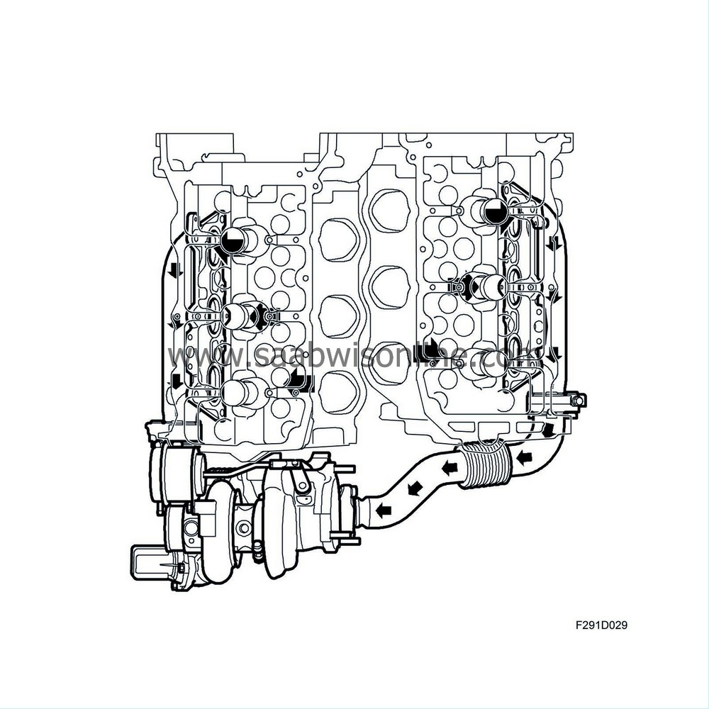
| Twin scroll |

| • |
Quicker turbocharger response
|
|
| • |
Considerably fewer disruptions between cylinders during the flushing phase.
|
|
By using the energy of the exhaust pulses as a propelling force rather than the more or less constant flow of exhaust gases, the turbocharger reacts quicker. There is also a lower average pressure in the exhaust gases, which is good for engine ventilation. Because there is a difference of 240 crankshaft degrees between the exhaust strokes in the respective exhaust manifold, the exhaust pulse will have subsided when the next cylinder opens its exhaust valves. There is little flow of exhaust gases from the exhaust manifold into the cylinder, resulting in efficient cleansing with low residual gas content.
| Turbo adjustment |

General
The charge air pressure is mainly due to engine speed and load. At low engine loads, the exhaust gas volume driving the turbine is relatively small and all the exhaust gas needs to pass the turbine in order to drive the turbine wheel and compressor.When the engine load is somewhat higher, the exhaust gas volume will also be larger. This means that the energy driving the turbo is greater and the compressor therefore forces more air into the engine.
If the engine load rises further, the exhaust gas volume produced by the engine will be greater than that needed to drive the compressor in order to provide the correct air mass per combustion. At high loads, the volume of gases reaching the turbine must therefore be limited so that the turbocharger produces the correct airflow. This is achieved with a valve, called wastegate, opening a bypass passage parallel with the turbine. The excess gas not required to drive the turbine passes through this passage.
Turbo control at low loads
At low loads, the wastegate valve is closed. All the exhaust gas then passes through the turbine.
Turbo control at high loads
At high loads, the volume of exhaust gas is greater, which makes the turbine wheel rotate faster. This delivers a greater air displacement to the engine.When the air displacement becomes so large that the current air mass per combustion cannot be controlled with the throttle alone, the turbo must be regulated. This is done by opening the wastegate valve so that some of the exhaust gas passes through the wastegate. Consequently, this gas does not contribute to driving the turbine and the turbine speed will be regulated so that the turbo air displacement will be correct.

| Wastegate valve |
The wastegate valve is a clack valve that opens and closes a bypass passage beside the turbine wheel. The valve is controlled by a diaphragm box on the compressor housing.

Controlling the wastegate valve
The wastegate valve is actuated by a rod from the diaphragm box located at the compressor housing. A spiral spring in the diaphragm box box works in the closing direction while the pressure in the diaphragm works in the opening direction. The engine management system supplies a PWM signal to a solenoid valve, which then allows pressure from the compressor to come through. When the pressure overcomes the spring force in the diaphragm box, its rod begins to move, opening the wastegate valve to a corresponding degree. The engine management system changes wastegate valve opening by varying the PWM signal. In this way, turbine speed can be regulated.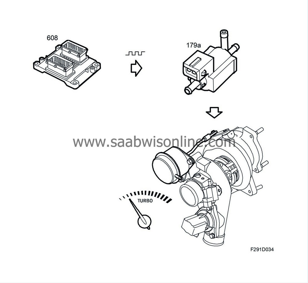
| Solenoid valve, turbo bypass (605) |

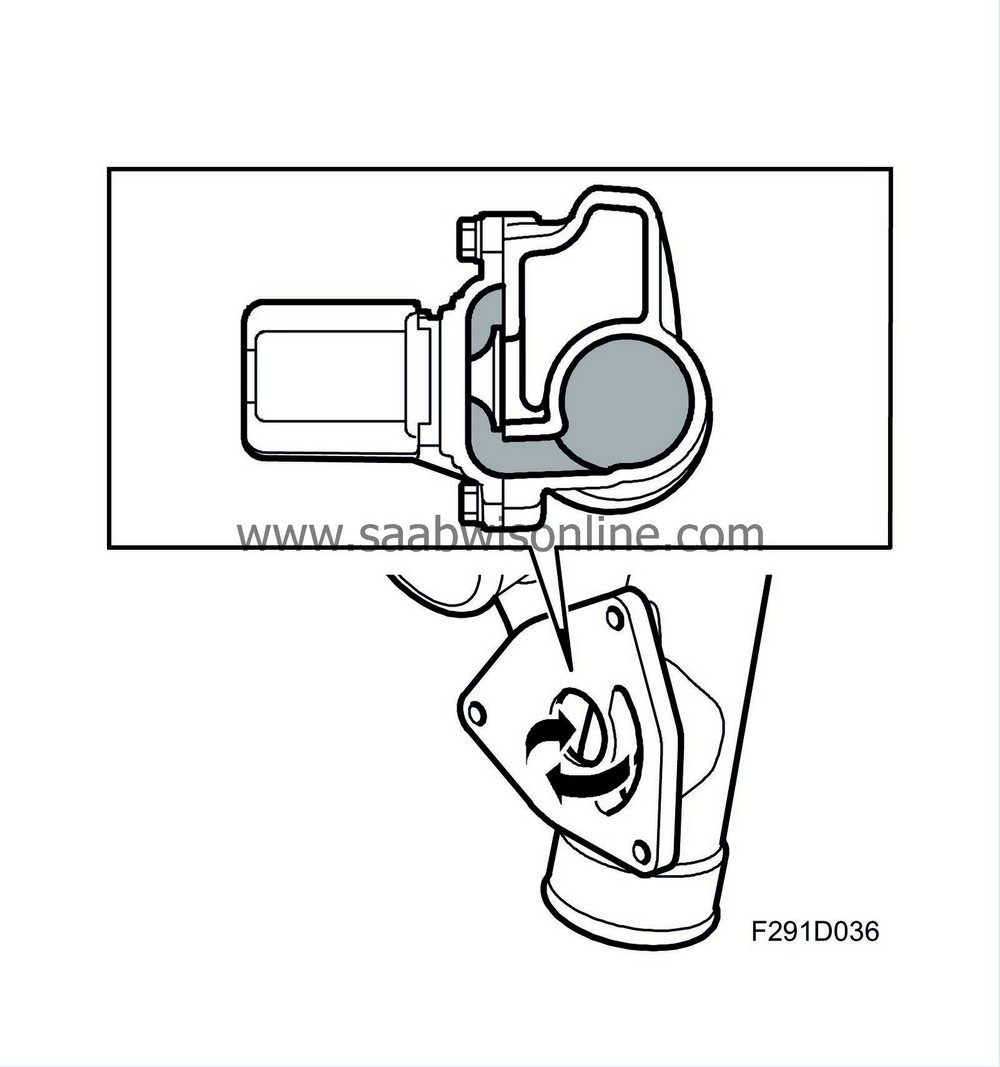
The bypass valve prevents the compressor component from exceeding the pump limit at low compressor flow and high pressure. This occurs when the engine is run with a load and the throttle suddenly closes. In this case, flow is almost null and pressure is very high. This not only is damaging to the turbocharger, but also generates noise and decelerates turbine speed. The valve is an electric valve bolted to the turbocharger compressor housing. ECM regulates valve position (open or closed) via a PWM voltage.
Accelerator depressed
Bypass valve is closed. The force in one of the return springs integrated in the valve presses the valve cone against its seat in the compressor housing. The valve is de-energised.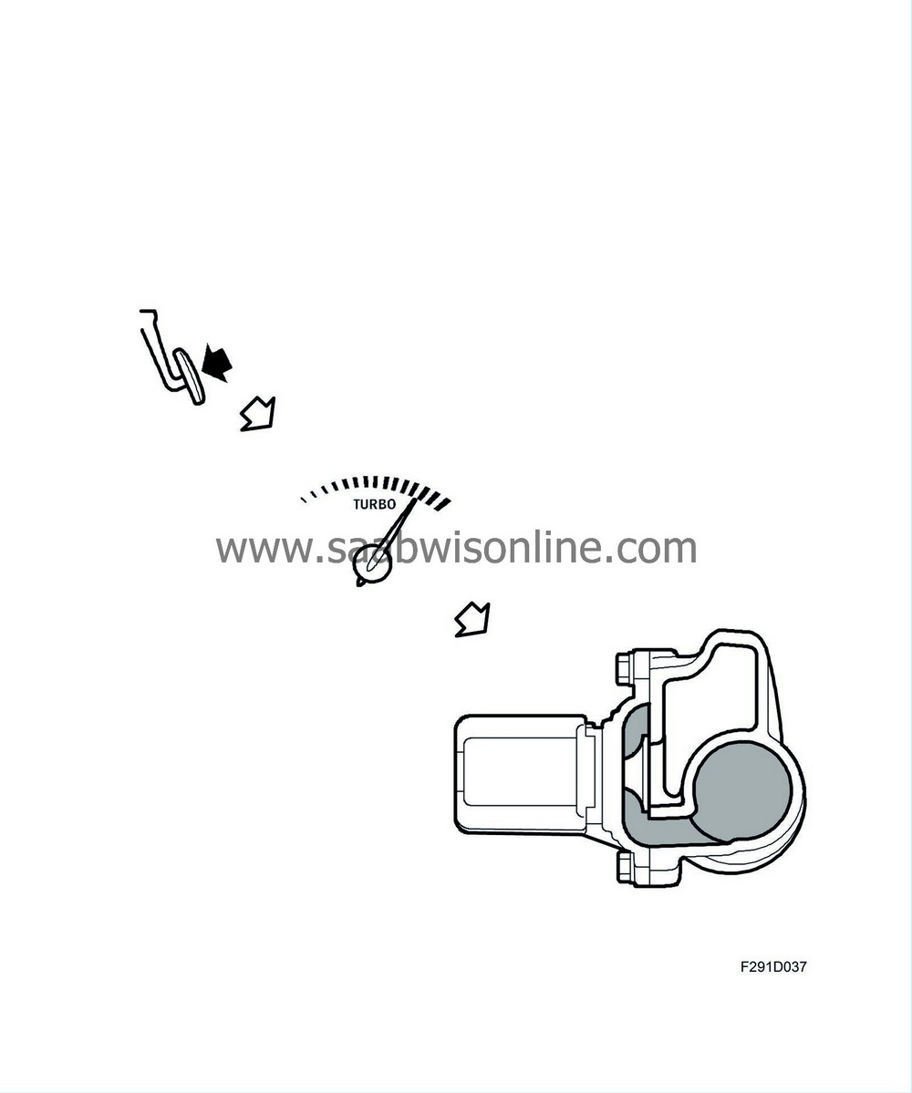
When the accelerator is released
In order to avoid pressure spikes in the intake manifold and unload the compressor, ECM sends a PWM voltage to the relief valve, which will then open. The compressed air on the pressure side of the compressor is led to the compressor intake via the open valve. Pressure sinks, turbine speed can be kept relatively high and the compressor is prevented from breaking through the pump limit. By using an electric bypass valve, ECM can control valve position regardless of whether there is a vacuum, which is normally the case. The electric bypass valve can be opened a bit earlier and quicker when the accelerator pedal is released compared to a conventional vacuum-operated valve. This allows the turbine speed to remain high during gearshifting and the like. The response in engine torque becomes quicker and more powerful when the driver once again depresses the accelerator pedal as a result of this.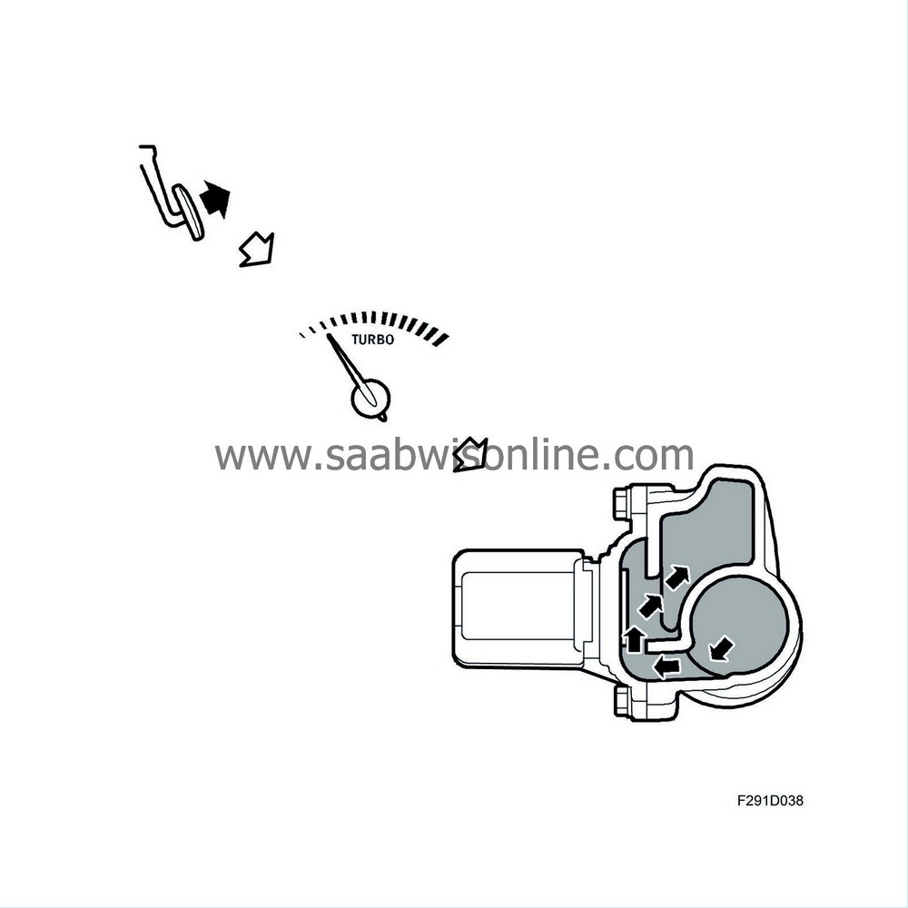
| Diaphragm unit |
The diaphragm box is controlled through a hose from the turbocharger via a solenoid valve. A coil spring in the diaphragm box normally keeps the wastegate valve closed. When the engine management system wants to regulate the charge air pressure, it sends a PWM signal to the solenoid valve to open it. The charge air pressure via the hose from the turbocharger overcomes the force of the coil spring in the diaphragm box and the wastegate valve starts to open.

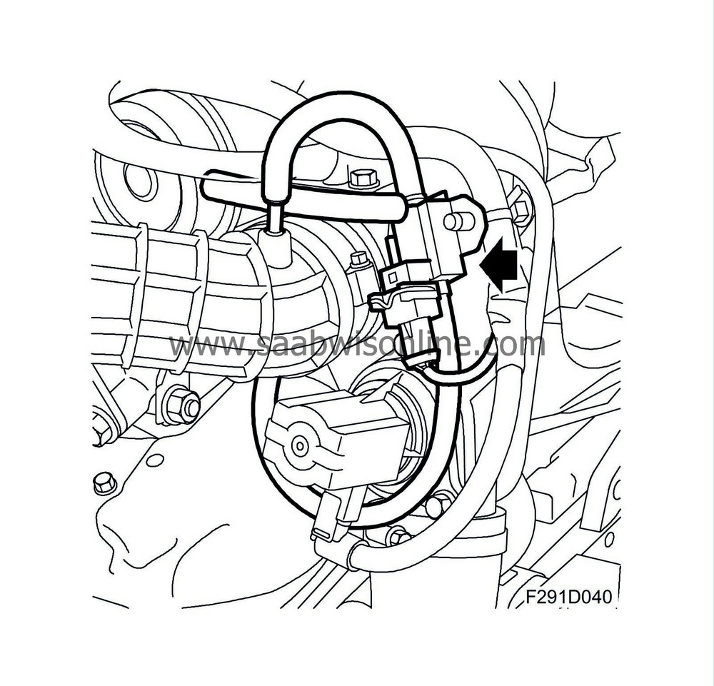
| Boost pressure control valve (179a) |
The solenoid valve is controlled by the engine control module via a PWM signal that opens the valve to allow the charge air pressure to act on the wastegate valve.
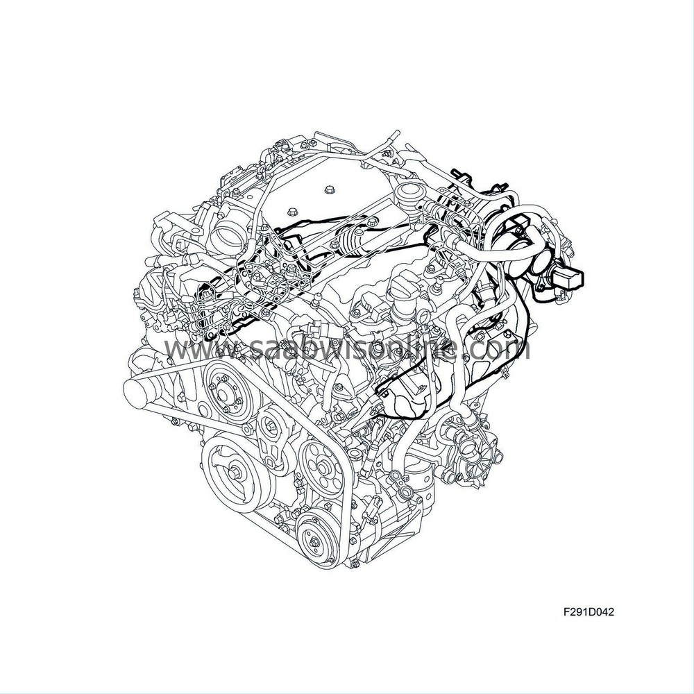
| Exhaust manifold |
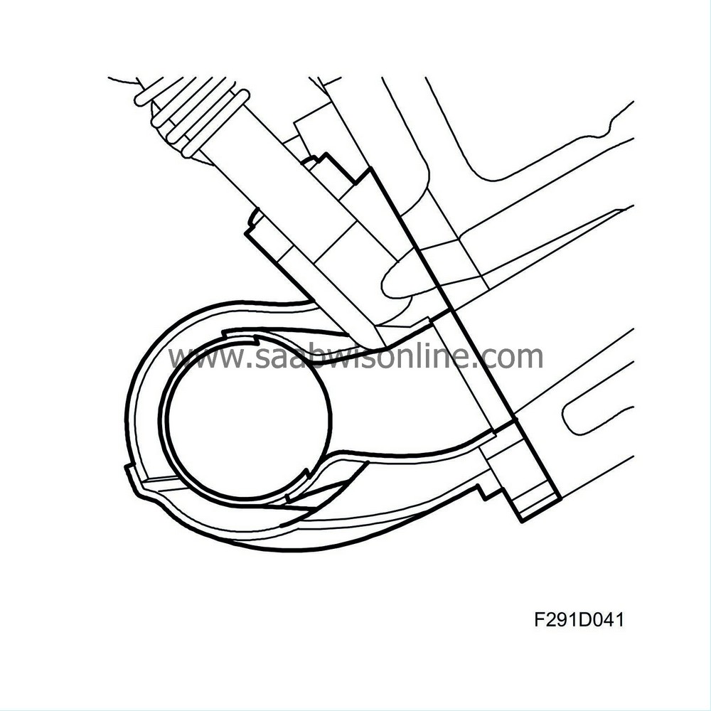
The exhaust manifold is made of hydroformed, dual coated steel plating that is welded to a flange that is bolted to the cylinder head. Hydroforming allows great freedom in providing the exhaust manifold an optimal shape for both flow and space. The dual coating reduces noise from the exhaust manifold and heat radiation to the environment. As little heat loss as possible is important both to reduce the temperature in the engine compartment and to maintain a high exhaust gas temperature for quick catalytic converter ignition during a cold start.
The exhaust manifold is connected via a flange to the pipe leading to the turbine. The pipes between the exhaust manifold and the turbine have a dual coating and are equipped with a flex component.
| Lubrication |
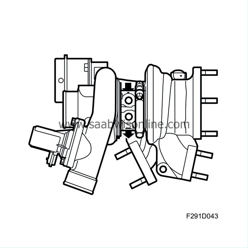
The turbo shaft, which rotates at a very high speed, is precisely balanced and supported in fixed plain bearing bushings. This bearing arrangement demands a high flow of oil, which makes the shaft rotate on a cushion of oil. This oil comes from the engine lubricating system through a special oil line leading from the oil filter adapter housing. The return oil passes to the engine oil sump. The seal between the shaft and the bearing housing comprises rings (similar to piston rings) located in grooves in the shaft.
| Cooling |
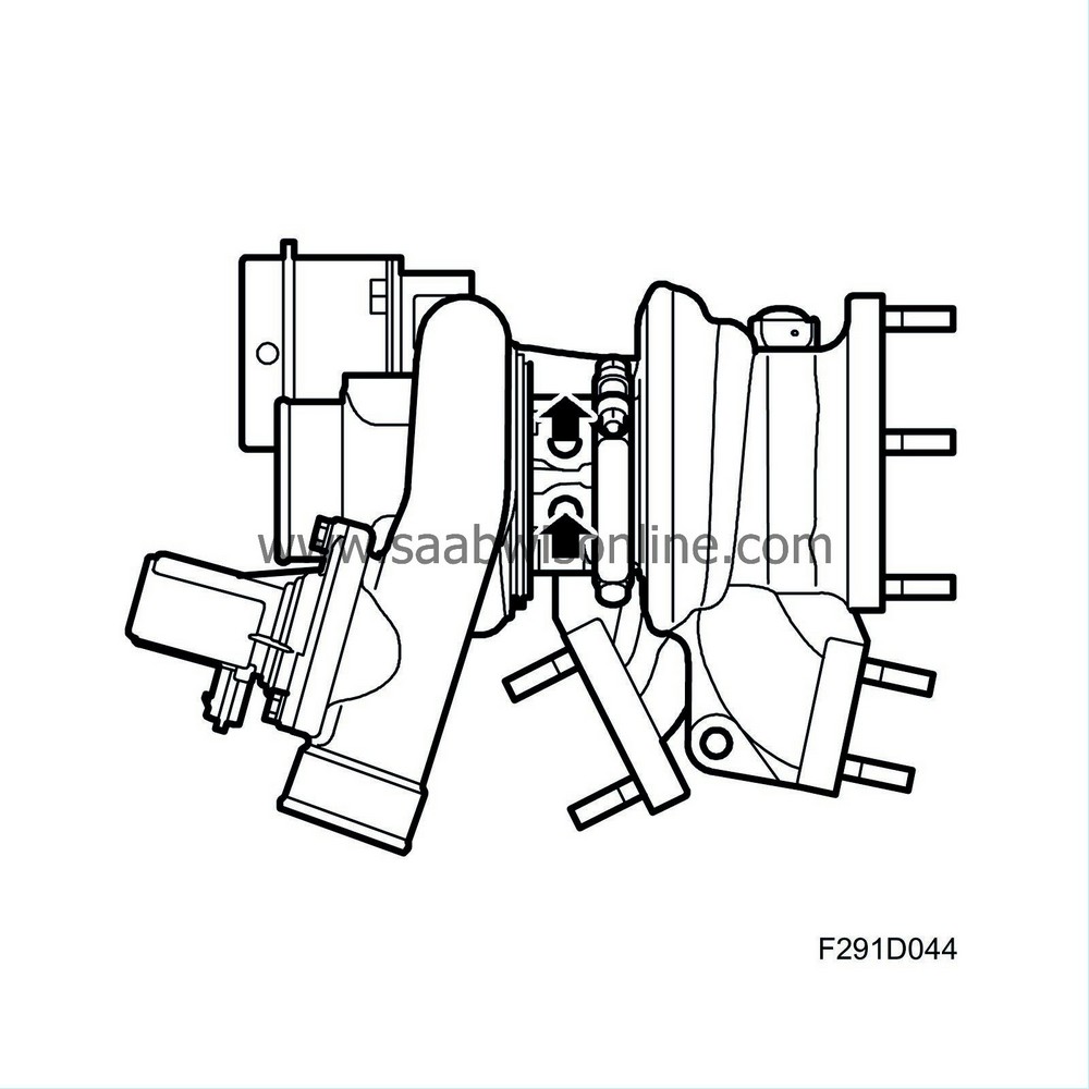
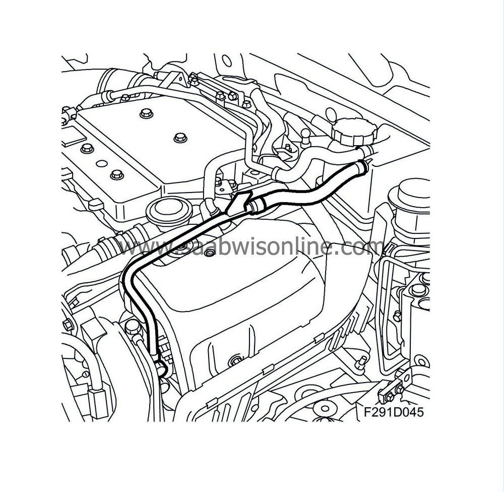
The turbocharger is water cooled, which considerably lowers the temperature in the bearing housing. Temperature reduction reduces the risk of oil boiling and the resulting damage. The coolant is taken via a pipe from the front of the cylinder block.
After passing the bearing housing, the coolant is led on via pipes to the expansion tank. When the engine is switched off and the coolant pump has stopped, the coolant in the system self-circulates through thermosyphoning. After the engine has been run hard, a boiling/bubbling noise may be audible. This is completely normal. (The illustration depicts coolant flow when the engine is running).
